1993 FORD MONDEO height adjustment
[x] Cancel search: height adjustmentPage 173 of 279

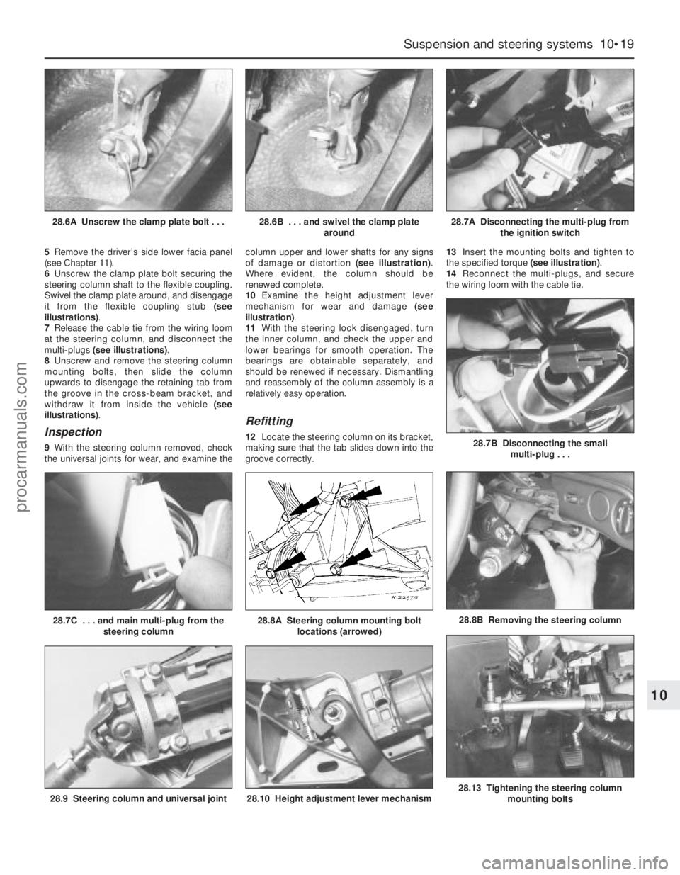
5Remove the driver’s side lower facia panel
(see Chapter 11).
6Unscrew the clamp plate bolt securing the
steering column shaft to the flexible coupling.
Swivel the clamp plate around, and disengage
it from the flexible coupling stub (see
illustrations).
7Release the cable tie from the wiring loom
at the steering column, and disconnect the
multi-plugs (see illustrations).
8Unscrew and remove the steering column
mounting bolts, then slide the column
upwards to disengage the retaining tab from
the groove in the cross-beam bracket, and
withdraw it from inside the vehicle (see
illustrations).
Inspection
9With the steering column removed, check
the universal joints for wear, and examine thecolumn upper and lower shafts for any signs
of damage or distortion (see illustration).
Where evident, the column should be
renewed complete.
10Examine the height adjustment lever
mechanism for wear and damage (see
illustration).
11With the steering lock disengaged, turn
the inner column, and check the upper and
lower bearings for smooth operation. The
bearings are obtainable separately, and
should be renewed if necessary. Dismantling
and reassembly of the column assembly is a
relatively easy operation.
Refitting
12Locate the steering column on its bracket,
making sure that the tab slides down into the
groove correctly.13Insert the mounting bolts and tighten to
the specified torque (see illustration).
14Reconnect the multi-plugs, and secure
the wiring loom with the cable tie.
Suspension and steering systems 10•19
10
28.9 Steering column and universal joint28.10 Height adjustment lever mechanism28.13 Tightening the steering column
mounting bolts
28.7C . . . and main multi-plug from the
steering column28.8A Steering column mounting bolt
locations (arrowed)28.8B Removing the steering column
28.6A Unscrew the clamp plate bolt . . .28.6B . . . and swivel the clamp plate
around28.7A Disconnecting the multi-plug from
the ignition switch
28.7B Disconnecting the small
multi-plug . . .
procarmanuals.com
Page 176 of 279

3Start the engine, and allow it to run at a fast
idle. Check the hoses and connections for
leaks.
4Stop the engine, and recheck the fluid level.
Add more if necessary, up to the “MAX” or
“MAX COLD” mark.
5Start the engine again, allow it to idle, then
bleed the system by slowly turning the
steering wheel from side to side several times.
This should purge the system of all internal
air. However, if air remains in the system
(indicated by the steering operation being very
noisy), leave the vehicle overnight, and repeat
the procedure again the next day.
6If air still remains in the system, it may be
necessary to resort to the Ford method of
bleeding, which uses a vacuum pump. Turn
the steering to the right until it is near the stop,
then fit the vacuum pump to the fluid
reservoir, and apply 0.15 bars of vacuum.
Maintain the vacuum for a minimum of
5 minutes, then repeat the procedure with the
steering turned to the left.
7Keep the fluid level topped-up throughout
the bleeding procedure; note that, as the fluid
temperature increases, the level will rise.
8On completion, switch off the engine, and
return the front wheels to the straight-ahead
position.
Removal
1Disconnect the battery negative (earth) lead
(refer to Chapter 5, Section 1).
2Unscrew and remove the bolt securing the
hydraulic fluid line support to the engine lifting
bracket on the right-hand side of the engine.
3Unscrew and remove the bolt securing the
hydraulic fluid line support to the pump
mounting bracket.
4Position a suitable container beneath the
power steering pump, to catch spilt fluid.
5Loosen the clip, and disconnect the fluid
supply hose from the pump inlet. Plug the
hose, to prevent the ingress of dust and dirt.
6Unscrew the union nut, and disconnect the
high-pressure line from the pump. Allow the
fluid to drain into the container.
7Apply the handbrake, then jack up the front
of the vehicle and support it on axle stands.
Remove the right-hand front wheel.
8Unbolt and remove the lower drivebelt
cover.
9Using a spanner, rotate the drivebelt
tensioner in a clockwise direction to release
the belt tension, then slip the drivebelt off the
pulleys and remove from the vehicle. Refer to
Chapter 1 if necessary.
10Unscrew and remove the four mounting
bolts, and withdraw the power steering pump
from its bracket. Access to the bolts on the
right-hand side of the engine is gained by
turning the pump pulley until a hole lines up
with the bolt.
Refitting
11Locate the power steering pump on the
mounting bracket, and secure with the four
bolts. Tighten the bolts to the specified
torque.
12Slip the drivebelt over the pulleys, then
rotate the drivebelt tensioner in a clockwise
direction, and locate the drivebelt on it.
Release the tensioner to tension the drivebelt.
13Refit the lower belt cover.
14Refit the right-hand front wheel, and lower
the vehicle to the ground.
15If necessary, the sealing ring on the high-
pressure outlet should be renewed, using the
same procedure as described in Section 30,
paragraph 8.
16Reconnect the high-pressure line to the
pump, and tighten the union nut.
17Reconnect the fluid supply hose to the
pump inlet, and tighten the clip.
18Refit the hydraulic fluid line support to the
pump mounting bracket, and tighten the bolt.
19Refit the hydraulic fluid line support to the
engine lifting bracket on the right-hand side of
the engine, and tighten the bolt.
20Reconnect the battery negative lead.
21Bleed the power steering hydraulic
system as described in Section 33.
1Apply the handbrake, then jack up the front
of the vehicle and support it on axle stands.
Remove the appropriate front roadwheel.
2Using a suitable spanner, slacken the
locknut on the track rod by a quarter-turn.
Hold the track rod end stationary with another
spanner engaged with the special flats while
loosening the locknut.
3Extract the split pin, then unscrew and
remove the track rod end balljoint retaining
nut.
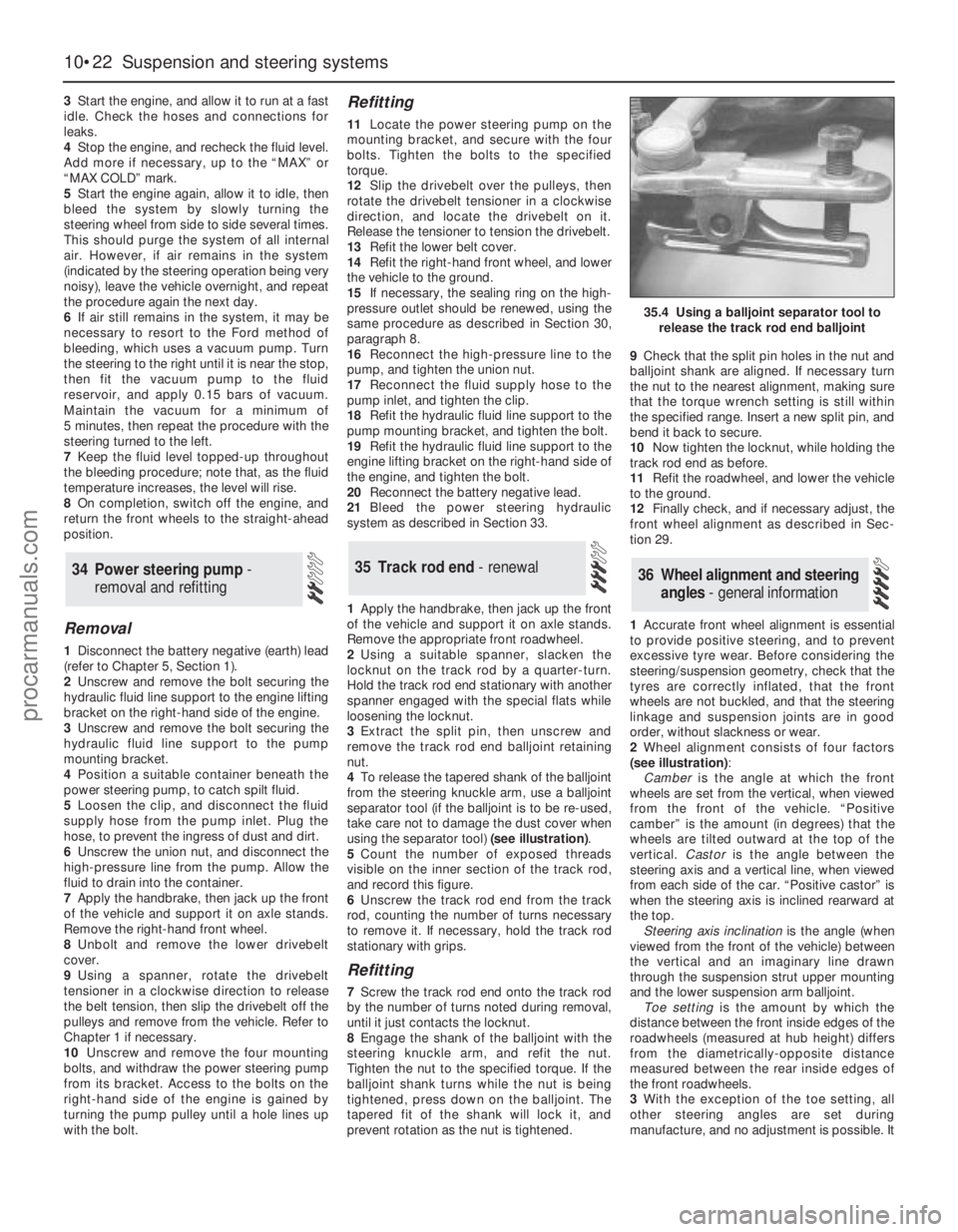
4To release the tapered shank of the balljoint
from the steering knuckle arm, use a balljoint
separator tool (if the balljoint is to be re-used,
take care not to damage the dust cover when
using the separator tool) (see illustration).
5Count the number of exposed threads
visible on the inner section of the track rod,
and record this figure.
6Unscrew the track rod end from the track
rod, counting the number of turns necessary
to remove it. If necessary, hold the track rod
stationary with grips.
Refitting
7Screw the track rod end onto the track rod
by the number of turns noted during removal,
until it just contacts the locknut.
8Engage the shank of the balljoint with the
steering knuckle arm, and refit the nut.
Tighten the nut to the specified torque. If the
balljoint shank turns while the nut is being
tightened, press down on the balljoint. The
tapered fit of the shank will lock it, and
prevent rotation as the nut is tightened.9Check that the split pin holes in the nut and
balljoint shank are aligned. If necessary turn
the nut to the nearest alignment, making sure
that the torque wrench setting is still within
the specified range. Insert a new split pin, and
bend it back to secure.
10Now tighten the locknut, while holding the
track rod end as before.
11Refit the roadwheel, and lower the vehicle
to the ground.
12Finally check, and if necessary adjust, the
front wheel alignment as described in Sec-
tion 29.
1Accurate front wheel alignment is essential
to provide positive steering, and to prevent
excessive tyre wear. Before considering the
steering/suspension geometry, check that the
tyres are correctly inflated, that the front
wheels are not buckled, and that the steering
linkage and suspension joints are in good
order, without slackness or wear.
2Wheel alignment consists of four factors
(see illustration):
Camberis the angle at which the front
wheels are set from the vertical, when viewed
from the front of the vehicle. “Positive
camber” is the amount (in degrees) that the
wheels are tilted outward at the top of the
vertical. Castoris the angle between the
steering axis and a vertical line, when viewed
from each side of the car. “Positive castor” is
when the steering axis is inclined rearward at
the top.
Steering axis inclinationis the angle (when
viewed from the front of the vehicle) between
the vertical and an imaginary line drawn
through the suspension strut upper mounting
and the lower suspension arm balljoint.
Toe settingis the amount by which the
distance between the front inside edges of the
roadwheels (measured at hub height) differs
from the diametrically-opposite distance
measured between the rear inside edges of
the front roadwheels.
3With the exception of the toe setting, all
other steering angles are set during
manufacture, and no adjustment is possible. It
36 Wheel alignment and steering
angles - general information35 Track rod end - renewal34 Power steering pump -
removal and refitting
10•22 Suspension and steering systems
35.4 Using a balljoint separator tool to
release the track rod end balljoint
procarmanuals.com
Page 183 of 279

11.3B . . . and disconnect the multi-plug
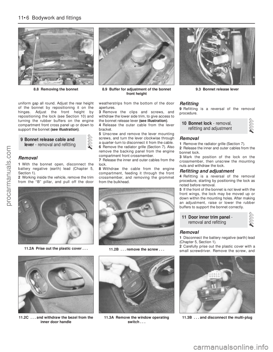
uniform gap all round. Adjust the rear height
of the bonnet by repositioning it on the
hinges. Adjust the front height by
repositioning the lock (see Section 10) and
turning the rubber buffers on the engine
compartment front cross panel up or down to
support the bonnet (see illustration).
Removal
1With the bonnet open, disconnect the
battery negative (earth) lead (Chapter 5,
Section 1).
2Working inside the vehicle, remove the trim
from the “B” pillar, and pull off the doorweatherstrips from the bottom of the door
apertures.
3Remove the clips and screws, and
withdraw the lower side trim, to give access to
the bonnet release lever (see illustration).
4Release the outer cable from the lever
bracket.
5Unscrew and remove the lever mounting
screws, and turn the lever clockwise through
a quarter-turn to disconnect it from the cable.
6Remove the radiator grille (Section 7). Also
remove the backing panel from the engine
compartment front crossmember.
7Release the inner and outer cables from the
lock.
8Withdraw the cable from the engine
compartment, feeding it through the front
crossmember, and removing the grommet
from the bulkhead.
Refitting
9Refitting is a reversal of the removal
procedure.
Removal
1Remove the radiator grille (Section 7).
2Release the inner and outer cables from the
bonnet lock.
3Mark the position of the lock on the
crossmember, then unscrew the mounting
nuts and withdraw the lock.
Refitting and adjustment
4Refitting is a reversal of the removal
procedure, starting by positioning the lock as
noted before removal.
5If the front of the bonnet is not level with the
front wings, the lock may be moved up or
down within the mounting holes. After making
an adjustment, raise or lower the rubber
buffers to support the bonnet correctly.
Removal
1Disconnect the battery negative (earth) lead
(Chapter 5, Section 1).
2Carefully prise out the plastic cover with a
small screwdriver. Remove the screw, and
11 Door inner trim panel -
removal and refitting
10 Bonnet lock - removal,
refitting and adjustment
9 Bonnet release cable and
lever - removal and refitting
11•6 Bodywork and fittings
8.8 Removing the bonnet8.9 Buffer for adjustment of the bonnet
front height9.3 Bonnet release lever
11.2B . . . remove the screw . . .11.2A Prise out the plastic cover . . .
11.2C . . . and withdraw the bezel from the
inner door handle11.3A Remove the window operating
switch . . .
procarmanuals.com