1993 FORD MONDEO gas type
[x] Cancel search: gas typePage 5 of 279
Working on your car can be dangerous.
This page shows just some of the potential
risks and hazards, with the aim of creating a
safety-conscious attitude.
General hazards
Scalding
• Don’t remove the radiator or expansion
tank cap while the engine is hot.
• Engine oil, automatic transmission fluid or
power steering fluid may also be dangerously
hot if the engine has recently been running.
Burning
• Beware of burns from the exhaust system
and from any part of the engine. Brake discs
and drums can also be extremely hot
immediately after use.
Crushing
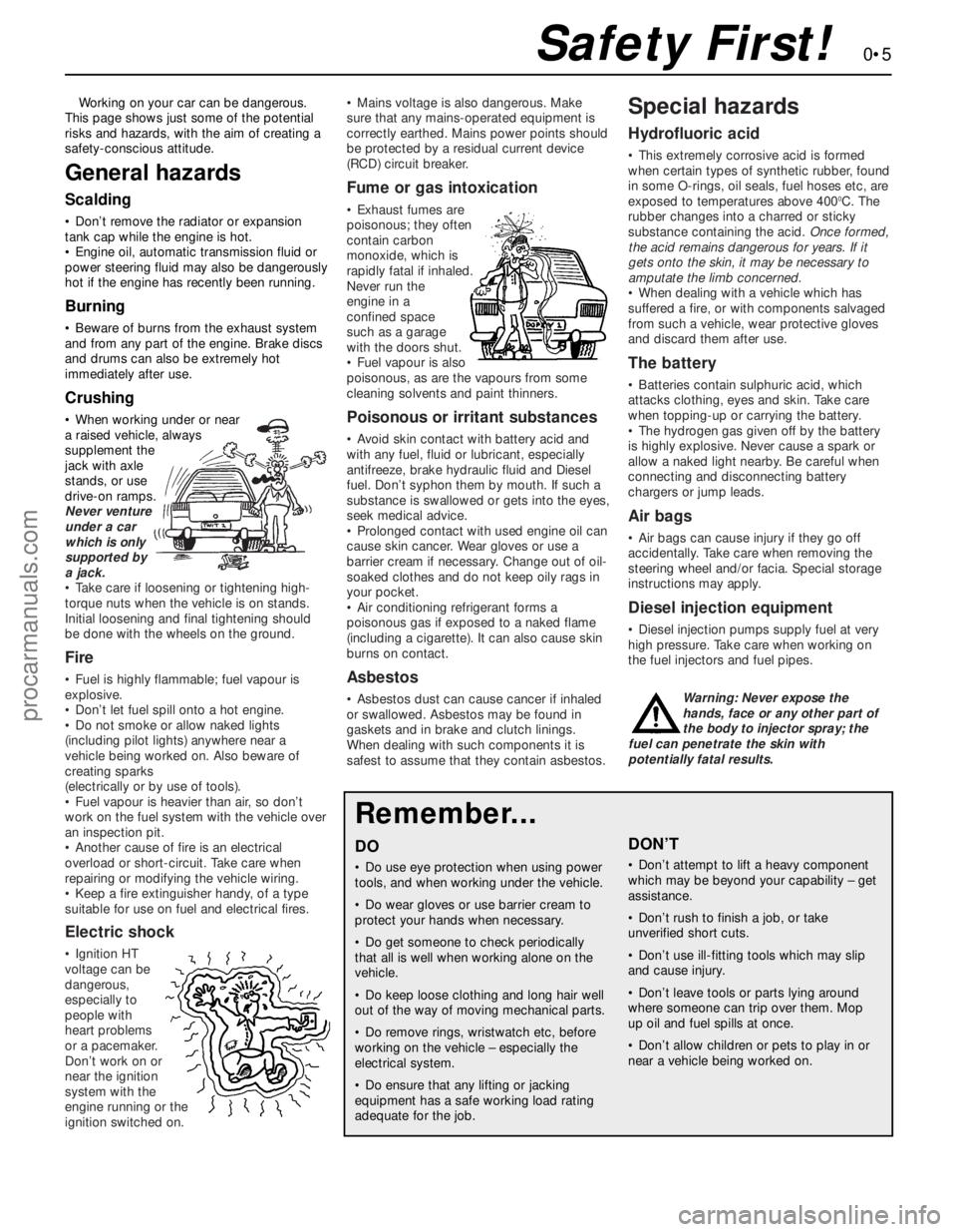
• When working under or near
a raised vehicle, always
supplement the
jack with axle
stands, or use
drive-on ramps.
Never venture
under a car
which is only
supported by
a jack.
• Take care if loosening or tightening high-
torque nuts when the vehicle is on stands.
Initial loosening and final tightening should
be done with the wheels on the ground.
Fire
• Fuel is highly flammable; fuel vapour is
explosive.
• Don’t let fuel spill onto a hot engine.
• Do not smoke or allow naked lights
(including pilot lights) anywhere near a
vehicle being worked on. Also beware of
creating sparks
(electrically or by use of tools).
• Fuel vapour is heavier than air, so don’t
work on the fuel system with the vehicle over
an inspection pit.
• Another cause of fire is an electrical
overload or short-circuit. Take care when
repairing or modifying the vehicle wiring.
• Keep a fire extinguisher handy, of a type
suitable for use on fuel and electrical fires.
Electric shock
• Ignition HT
voltage can be
dangerous,
especially to
people with
heart problems
or a pacemaker.
Don’t work on or
near the ignition
system with the
engine running or the
ignition switched on.• Mains voltage is also dangerous. Make
sure that any mains-operated equipment is
correctly earthed. Mains power points should
be protected by a residual current device
(RCD) circuit breaker.
Fume or gas intoxication
• Exhaust fumes are
poisonous; they often
contain carbon
monoxide, which is
rapidly fatal if inhaled.
Never run the
engine in a
confined space
such as a garage
with the doors shut.
• Fuel vapour is also
poisonous, as are the vapours from some
cleaning solvents and paint thinners.
Poisonous or irritant substances
• Avoid skin contact with battery acid and
with any fuel, fluid or lubricant, especially
antifreeze, brake hydraulic fluid and Diesel
fuel. Don’t syphon them by mouth. If such a
substance is swallowed or gets into the eyes,
seek medical advice.
• Prolonged contact with used engine oil can
cause skin cancer. Wear gloves or use a
barrier cream if necessary. Change out of oil-
soaked clothes and do not keep oily rags in
your pocket.
• Air conditioning refrigerant forms a
poisonous gas if exposed to a naked flame
(including a cigarette). It can also cause skin
burns on contact.
Asbestos
• Asbestos dust can cause cancer if inhaled
or swallowed. Asbestos may be found in
gaskets and in brake and clutch linings.
When dealing with such components it is
safest to assume that they contain asbestos.
Special hazards
Hydrofluoric acid
• This extremely corrosive acid is formed
when certain types of synthetic rubber, found
in some O-rings, oil seals, fuel hoses etc, are
exposed to temperatures above 400
0C. The
rubber changes into a charred or sticky
substance containing the acid. Once formed,
the acid remains dangerous for years. If it
gets onto the skin, it may be necessary to
amputate the limb concerned.
• When dealing with a vehicle which has
suffered a fire, or with components salvaged
from such a vehicle, wear protective gloves
and discard them after use.
The battery
• Batteries contain sulphuric acid, which
attacks clothing, eyes and skin. Take care
when topping-up or carrying the battery.
• The hydrogen gas given off by the battery
is highly explosive. Never cause a spark or
allow a naked light nearby. Be careful when
connecting and disconnecting battery
chargers or jump leads.
Air bags
• Air bags can cause injury if they go off
accidentally. Take care when removing the
steering wheel and/or facia. Special storage
instructions may apply.
Diesel injection equipment
• Diesel injection pumps supply fuel at very
high pressure. Take care when working on
the fuel injectors and fuel pipes.
Warning: Never expose the
hands, face or any other part of
the body to injector spray; the
fuel can penetrate the skin with
potentially fatal results.
Remember...
DO
• Do use eye protection when using power
tools, and when working under the vehicle.
• Do wear gloves or use barrier cream to
protect your hands when necessary.
• Do get someone to check periodically
that all is well when working alone on the
vehicle.
• Do keep loose clothing and long hair well
out of the way of moving mechanical parts.
• Do remove rings, wristwatch etc, before
working on the vehicle – especially the
electrical system.
• Do ensure that any lifting or jacking
equipment has a safe working load rating
adequate for the job.
A few tips
DON’T
• Don’t attempt to lift a heavy component
which may be beyond your capability – get
assistance.
• Don’t rush to finish a job, or take
unverified short cuts.
• Don’t use ill-fitting tools which may slip
and cause injury.
• Don’t leave tools or parts lying around
where someone can trip over them. Mop
up oil and fuel spills at once.
• Don’t allow children or pets to play in or
near a vehicle being worked on.
0•5Safety First!
procarmanuals.com
Page 10 of 279
0•10
MExamine the handbrake mechanism,
checking for frayed or broken cables,
excessive corrosion, or wear or insecurity of
the linkage. Check that the mechanism works
on each relevant wheel, and releases fully,
without binding.
MIt is not possible to test brake efficiency
without special equipment, but a road test
can be carried out later to check that the
vehicle pulls up in a straight line.
Fuel and exhaust systems
MInspect the fuel tank (including the filler
cap), fuel pipes, hoses and unions. All
components must be secure and free from
leaks.
MExamine the exhaust system over its entire
length, checking for any damaged, broken or
missing mountings, security of the retaining
clamps and rust or corrosion.
Wheels and tyres
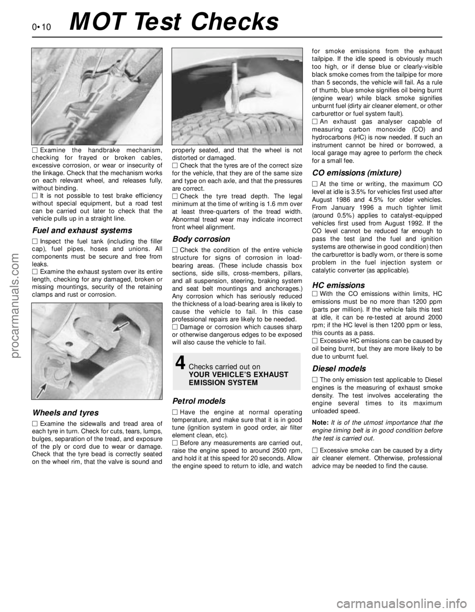
MExamine the sidewalls and tread area of
each tyre in turn. Check for cuts, tears, lumps,
bulges, separation of the tread, and exposure
of the ply or cord due to wear or damage.
Check that the tyre bead is correctly seated
on the wheel rim, that the valve is sound andproperly seated, and that the wheel is not
distorted or damaged.
MCheck that the tyres are of the correct size
for the vehicle, that they are of the same size
and type on each axle, and that the pressures
are correct.
MCheck the tyre tread depth. The legal
minimum at the time of writing is 1.6 mm over
at least three-quarters of the tread width.
Abnormal tread wear may indicate incorrect
front wheel alignment.
Body corrosion
MCheck the condition of the entire vehicle
structure for signs of corrosion in load-
bearing areas. (These include chassis box
sections, side sills, cross-members, pillars,
and all suspension, steering, braking system
and seat belt mountings and anchorages.)
Any corrosion which has seriously reduced
the thickness of a load-bearing area is likely to
cause the vehicle to fail. In this case
professional repairs are likely to be needed.
MDamage or corrosion which causes sharp
or otherwise dangerous edges to be exposed
will also cause the vehicle to fail.
Petrol models
MHave the engine at normal operating
temperature, and make sure that it is in good
tune (ignition system in good order, air filter
element clean, etc).
MBefore any measurements are carried out,
raise the engine speed to around 2500 rpm,
and hold it at this speed for 20 seconds. Allow
the engine speed to return to idle, and watchfor smoke emissions from the exhaust
tailpipe. If the idle speed is obviously much
too high, or if dense blue or clearly-visible
black smoke comes from the tailpipe for more
than 5 seconds, the vehicle will fail. As a rule
of thumb, blue smoke signifies oil being burnt
(engine wear) while black smoke signifies
unburnt fuel (dirty air cleaner element, or other
carburettor or fuel system fault).
MAn exhaust gas analyser capable of
measuring carbon monoxide (CO) and
hydrocarbons (HC) is now needed. If such an
instrument cannot be hired or borrowed, a
local garage may agree to perform the check
for a small fee.
CO emissions (mixture)
MAt the time or writing, the maximum CO
level at idle is 3.5% for vehicles first used after
August 1986 and 4.5% for older vehicles.
From January 1996 a much tighter limit
(around 0.5%) applies to catalyst-equipped
vehicles first used from August 1992. If the
CO level cannot be reduced far enough to
pass the test (and the fuel and ignition
systems are otherwise in good condition) then
the carburettor is badly worn, or there is some
problem in the fuel injection system or
catalytic converter (as applicable).
HC emissionsMWith the CO emissions within limits, HC
emissions must be no more than 1200 ppm
(parts per million). If the vehicle fails this test
at idle, it can be re-tested at around 2000
rpm; if the HC level is then 1200 ppm or less,
this counts as a pass.
MExcessive HC emissions can be caused by
oil being burnt, but they are more likely to be
due to unburnt fuel.
Diesel models
MThe only emission test applicable to Diesel
engines is the measuring of exhaust smoke
density. The test involves accelerating the
engine several times to its maximum
unloaded speed.
Note: It is of the utmost importance that the
engine timing belt is in good condition before
the test is carried out.
M
Excessive smoke can be caused by a dirty
air cleaner element. Otherwise, professional
advice may be needed to find the cause.
4Checks carried out on
YOUR VEHICLE’S EXHAUST
EMISSION SYSTEM
MOT Test Checks
procarmanuals.com
Page 21 of 279
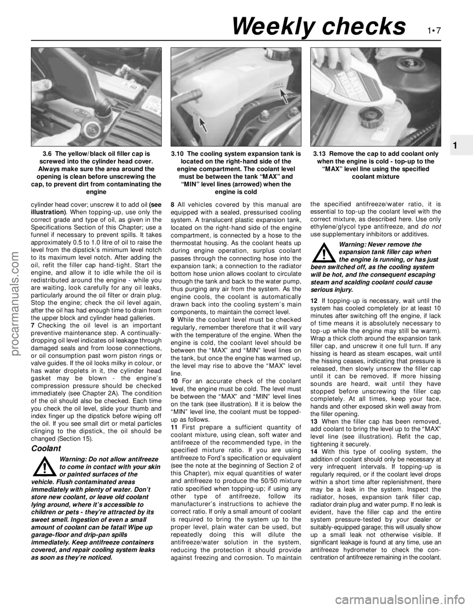
cylinder head cover; unscrew it to add oil (see
illustration). When topping-up, use only the
correct grade and type of oil, as given in the
Specifications Section of this Chapter; use a
funnel if necessary to prevent spills. It takes
approximately 0.5 to 1.0 litre of oil to raise the
level from the dipstick’s minimum level notch
to its maximum level notch. After adding the
oil, refit the filler cap hand-tight. Start the
engine, and allow it to idle while the oil is
redistributed around the engine - while you
are waiting, look carefully for any oil leaks,
particularly around the oil filter or drain plug.
Stop the engine; check the oil level again,
after the oil has had enough time to drain from
the upper block and cylinder head galleries.
7Checking the oil level is an important
preventive maintenance step. A continually-
dropping oil level indicates oil leakage through
damaged seals and from loose connections,
or oil consumption past worn piston rings or
valve guides. If the oil looks milky in colour, or
has water droplets in it, the cylinder head
gasket may be blown - the engine’s
compression pressure should be checked
immediately (see Chapter 2A). The condition
of the oil should also be checked. Each time
you check the oil level, slide your thumb and
index finger up the dipstick before wiping off
the oil. If you see small dirt or metal particles
clinging to the dipstick, the oil should be
changed (Section 15).
Coolant
Warning: Do not allow antifreeze
to come in contact with your skin
or painted surfaces of the
vehicle. Flush contaminated areas
immediately with plenty of water. Don’t
store new coolant, or leave old coolant
lying around, where it’s accessible to
children or pets - they’re attracted by its
sweet smell. Ingestion of even a small
amount of coolant can be fatal! Wipe up
garage-floor and drip-pan spills
immediately. Keep antifreeze containers
covered, and repair cooling system leaks
as soon as they’re noticed.8All vehicles covered by this manual are
equipped with a sealed, pressurised cooling
system. A translucent plastic expansion tank,
located on the right-hand side of the engine
compartment, is connected by a hose to the
thermostat housing. As the coolant heats up
during engine operation, surplus coolant
passes through the connecting hose into the
expansion tank; a connection to the radiator
bottom hose union allows coolant to circulate
through the tank and back to the water pump,
thus purging any air from the system. As the
engine cools, the coolant is automatically
drawn back into the cooling system’s main
components, to maintain the correct level.
9While the coolant level must be checked
regularly, remember therefore that it will vary
with the temperature of the engine. When the
engine is cold, the coolant level should be
between the “MAX” and “MIN” level lines on
the tank, but once the engine has warmed up,
the level may rise to above the “MAX” level
line.
10For an accurate check of the coolant
level, the engine must be cold. The level must
be between the “MAX” and “MIN” level lines
on the tank (see illustration). If it is below the
“MIN” level line, the coolant must be topped-
up as follows.
11First prepare a sufficient quantity of
coolant mixture, using clean, soft water and
antifreeze of the recommended type, in the
specified mixture ratio. If you are using
antifreeze to Ford’s specification or equivalent
(see the note at the beginning of Section 2 of
this Chapter), mix equal quantities of water
and antifreeze to produce the 50/50 mixture
ratio specified when topping-up; if using any
other type of antifreeze, follow its
manufacturer’s instructions to achieve the
correct ratio. If only a small amount of coolant
is required to bring the system up to the
proper level, plain water can be used, but
repeatedly doing this will dilute the
antifreeze/water solution in the system,
reducing the protection it should provide
against freezing and corrosion. To maintainthe specified antifreeze/water ratio, it is
essential to top-up the coolant level with the
correct mixture, as described here. Use only
ethylene/glycol type antifreeze, and do not
use supplementary inhibitors or additives.
Warning: Never remove the
expansion tank filler cap when
the engine is running, or has just
been switched off, as the cooling system
will be hot, and the consequent escaping
steam and scalding coolant could cause
serious injury.
12If topping-up is necessary, wait until the
system has cooled completely (or at least 10
minutes after switching off the engine, if lack
of time means it is absolutely necessary to
top-up while the engine may still be warm).
Wrap a thick cloth around the expansion tank
filler cap, and unscrew it one full turn. If any
hissing is heard as steam escapes, wait until
the hissing ceases, indicating that pressure is
released, then slowly unscrew the filler cap
until it can be removed. If more hissing
sounds are heard, wait until they have
stopped before unscrewing the filler cap
completely. At all times, keep your face,
hands and other exposed skin well away from
the filler opening.
13When the filler cap has been removed,
add coolant to bring the level up to the “MAX”
level line (see illustration). Refit the cap,
tightening it securely.
14With this type of cooling system, the
addition of coolant should only be necessary at
very infrequent intervals. If topping-up is
regularly required, or if the coolant level drops
within a short time after replenishment, there
may be a leak in the system. Inspect the
radiator, hoses, expansion tank filler cap,
radiator drain plug and water pump. If no leak is
evident, have the filler cap and the entire
system pressure-tested by your dealer or
suitably-equipped garage; this will usually show
up a small leak not otherwise visible. If
significant leakage is found at any time, use an
antifreeze hydrometer to check the con-
centration of antifreeze remaining in the coolant.
1•7
13.13 Remove the cap to add coolant only
when the engine is cold - top-up to the
“MAX” level line using the specified
coolant mixture3.6 The yellow/black oil filler cap is
screwed into the cylinder head cover.
Always make sure the area around the
opening is clean before unscrewing the
cap, to prevent dirt from contaminating the
engine3.10 The cooling system expansion tank is
located on the right-hand side of the
engine compartment. The coolant level
must be between the tank “MAX” and
“MIN” level lines (arrowed) when the
engine is cold
Weekly checks
procarmanuals.com
Page 33 of 279
evidence of leaks, severe corrosion, or
damage. Make sure that all brackets and
rubber mountings are in good condition, and
tight; if any of the mountings are to be
renewed, ensure that the replacements are of
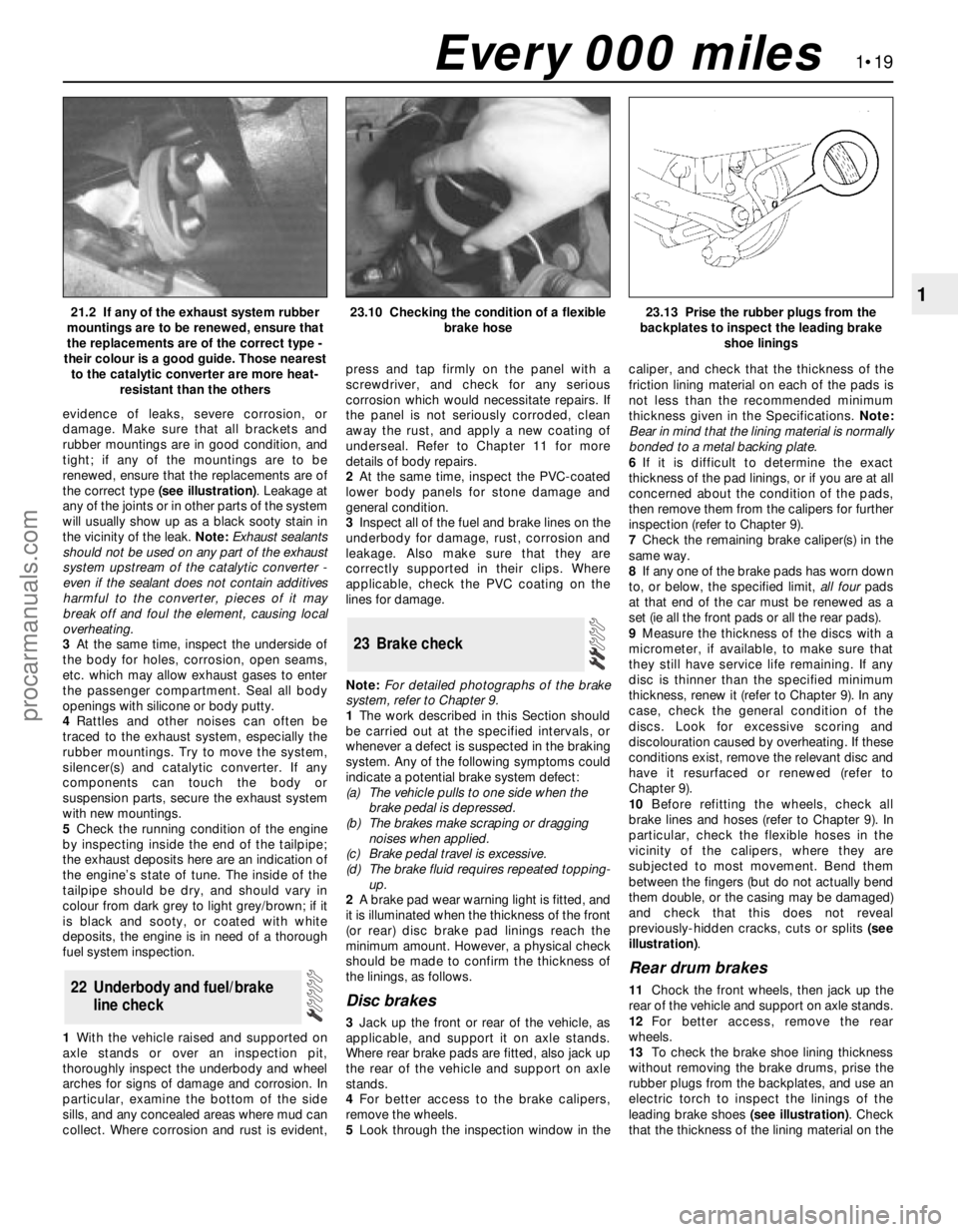
the correct type (see illustration). Leakage at
any of the joints or in other parts of the system
will usually show up as a black sooty stain in
the vicinity of the leak. Note:Exhaust sealants
should not be used on any part of the exhaust
system upstream of the catalytic converter -
even if the sealant does not contain additives
harmful to the converter, pieces of it may
break off and foul the element, causing local
overheating.
3At the same time, inspect the underside of
the body for holes, corrosion, open seams,
etc. which may allow exhaust gases to enter
the passenger compartment. Seal all body
openings with silicone or body putty.
4Rattles and other noises can often be
traced to the exhaust system, especially the
rubber mountings. Try to move the system,
silencer(s) and catalytic converter. If any
components can touch the body or
suspension parts, secure the exhaust system
with new mountings.
5Check the running condition of the engine
by inspecting inside the end of the tailpipe;
the exhaust deposits here are an indication of
the engine’s state of tune. The inside of the
tailpipe should be dry, and should vary in
colour from dark grey to light grey/brown; if it
is black and sooty, or coated with white
deposits, the engine is in need of a thorough
fuel system inspection.
1With the vehicle raised and supported on
axle stands or over an inspection pit,
thoroughly inspect the underbody and wheel
arches for signs of damage and corrosion. In
particular, examine the bottom of the side
sills, and any concealed areas where mud can
collect. Where corrosion and rust is evident,press and tap firmly on the panel with a
screwdriver, and check for any serious
corrosion which would necessitate repairs. If
the panel is not seriously corroded, clean
away the rust, and apply a new coating of
underseal. Refer to Chapter 11 for more
details of body repairs.
2At the same time, inspect the PVC-coated
lower body panels for stone damage and
general condition.
3Inspect all of the fuel and brake lines on the
underbody for damage, rust, corrosion and
leakage. Also make sure that they are
correctly supported in their clips. Where
applicable, check the PVC coating on the
lines for damage.
Note:For detailed photographs of the brake
system, refer to Chapter 9.
1The work described in this Section should
be carried out at the specified intervals, or
whenever a defect is suspected in the braking
system. Any of the following symptoms could
indicate a potential brake system defect:
(a) The vehicle pulls to one side when the
brake pedal is depressed.
(b) The brakes make scraping or dragging
noises when applied.
(c) Brake pedal travel is excessive.
(d) The brake fluid requires repeated topping-
up.
2A brake pad wear warning light is fitted, and
it is illuminated when the thickness of the front
(or rear) disc brake pad linings reach the
minimum amount. However, a physical check
should be made to confirm the thickness of
the linings, as follows.
Disc brakes
3Jack up the front or rear of the vehicle, as
applicable, and support it on axle stands.
Where rear brake pads are fitted, also jack up
the rear of the vehicle and support on axle
stands.
4For better access to the brake calipers,
remove the wheels.
5Look through the inspection window in thecaliper, and check that the thickness of the
friction lining material on each of the pads is
not less than the recommended minimum
thickness given in the Specifications. Note:
Bear in mind that the lining material is normally
bonded to a metal backing plate.
6If it is difficult to determine the exact
thickness of the pad linings, or if you are at all
concerned about the condition of the pads,
then remove them from the calipers for further
inspection (refer to Chapter 9).
7Check the remaining brake caliper(s) in the
same way.
8If any one of the brake pads has worn down
to, or below, the specified limit, all fourpads
at that end of the car must be renewed as a
set (ie all the front pads or all the rear pads).
9Measure the thickness of the discs with a
micrometer, if available, to make sure that
they still have service life remaining. If any
disc is thinner than the specified minimum
thickness, renew it (refer to Chapter 9). In any
case, check the general condition of the
discs. Look for excessive scoring and
discolouration caused by overheating. If these
conditions exist, remove the relevant disc and
have it resurfaced or renewed (refer to
Chapter 9).
10Before refitting the wheels, check all
brake lines and hoses (refer to Chapter 9). In
particular, check the flexible hoses in the
vicinity of the calipers, where they are
subjected to most movement. Bend them
between the fingers (but do not actually bend
them double, or the casing may be damaged)
and check that this does not reveal
previously-hidden cracks, cuts or splits (see
illustration).
Rear drum brakes
11Chock the front wheels, then jack up the
rear of the vehicle and support on axle stands.
12For better access, remove the rear
wheels.
13To check the brake shoe lining thickness
without removing the brake drums, prise the
rubber plugs from the backplates, and use an
electric torch to inspect the linings of the
leading brake shoes (see illustration). Check
that the thickness of the lining material on the
23 Brake check
22 Underbody and fuel/brake
line check
1•19
121.2 If any of the exhaust system rubber
mountings are to be renewed, ensure that
the replacements are of the correct type -
their colour is a good guide. Those nearest
to the catalytic converter are more heat-
resistant than the others23.10 Checking the condition of a flexible
brake hose23.13 Prise the rubber plugs from the
backplates to inspect the leading brake
shoe linings
Every 000 miles
procarmanuals.com
Page 36 of 279
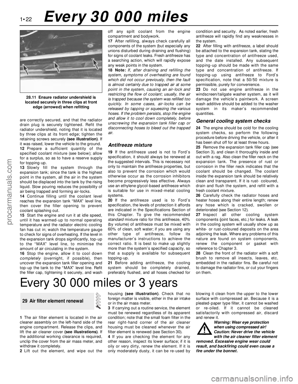
are correctly secured, and that the radiator
drain plug is securely tightened. Refit the
radiator undershield, noting that it is located
by three clips at its front edge; tighten the
retaining screws securely (see illustration). If
it was raised, lower the vehicle to the ground.
12Prepare a sufficient quantity of the
specified coolant mixture (see below); allow
for a surplus, so as to have a reserve supply
for topping-up.
13Slowly fill the system through the
expansion tank; since the tank is the highest
point in the system, all the air in the system
should be displaced into the tank by the rising
liquid. Slow pouring reduces the possibility of
air being trapped and forming air-locks.
14Continue filling until the coolant level
reaches the expansion tank “MAX” level line,
then cover the filler opening to prevent
coolant splashing out.
15Start the engine and run it at idle speed,
until it has warmed-up to normal operating
temperature and the radiator electric cooling
fan has cut in; watch the temperature gauge
to check for signs of overheating. If the level in
the expansion tank drops significantly, top-up
to the “MAX” level line, to minimise the
amount of air circulating in the system.
16Stop the engine, allow it to cool down
completely(overnight, if possible), then
uncover the expansion tank filler opening and
top-up the tank to the “MAX” level line. Refit
the filler cap, tightening it securely, and washoff any spilt coolant from the engine
compartment and bodywork.
17After refilling, always check carefully all
components of the system (but especially any
unions disturbed during draining and flushing)
for signs of coolant leaks. Fresh antifreeze has
a searching action, which will rapidly expose
any weak points in the system.
18 Note:If, after draining and refilling the
system, symptoms of overheating are found
which did not occur previously, then the fault
is almost certainly due to trapped air at some
point in the system, causing an air-lock and
restricting the flow of coolant; usually, the air
is trapped because the system was refilled too
quickly. In some cases, air-locks can be
released by tapping or squeezing the various
hoses. If the problem persists, stop the engine
and allow it to cool down completely, before
unscrewing the expansion tank filler cap or
disconnecting hoses to bleed out the trapped
air.
Antifreeze mixture
19If the antifreeze used is not to Ford’s
specification, it should always be renewed at
the suggested intervals. This is necessary not
only to maintain the antifreeze properties, but
also to prevent the corrosion which would
otherwise occur as the corrosion inhibitors
become progressively less effective. Always
use an ethylene glycol-based antifreeze which
is suitable for use in mixed-metal cooling
systems.
20If the antifreeze used is to Ford’s
specification, the levels of protection it affords
are indicated in the Specifications Section of
this Chapter. To give the recommended
standardmixture ratio for this antifreeze, 40%
(by volume) of antifreeze must be mixed with
60% of clean, soft water; if you are using any
other type of antifreeze, follow its
manufacturer’s instructions to achieve the
correct ratio. It is best to make up slightly
more than the system’s specified capacity, so
that a supply is available for subsequent
topping-up.
21Before adding antifreeze, the cooling
system should be completely drained,
preferably flushed, and all hoses checked forcondition and security. As noted earlier, fresh
antifreeze will rapidly find any weaknesses in
the system.
22After filling with antifreeze, a label should
be attached to the expansion tank, stating the
type and concentration of antifreeze used,
and the date installed. Any subsequent
topping-up should be made with the same
type and concentration of antifreeze. If
topping-up using antifreeze to Ford’s
specification, note that a 50/50 mixture is
permissible, purely for convenience.
23Do not use engine antifreeze in the
windscreen/tailgate washer system, as it will
damage the vehicle’s paintwork. A screen
wash additive should be added to the washer
system in its maker’s recommended
quantities.
General cooling system checks
24The engine should be cold for the cooling
system checks, so perform the following
procedure before driving the vehicle, or after it
has been shut off for at least three hours.
25Remove the expansion tank filler cap (see
Section 3), and clean it thoroughly inside and
out with a rag. Also clean the filler neck on the
expansion tank. The presence of rust or
corrosion in the filler neck indicates that the
coolant should be changed. The coolant
inside the expansion tank should be relatively
clean and transparent. If it is rust- coloured,
drain and flush the system, and refill with a
fresh coolant mixture.
26Carefully check the radiator hoses and
heater hoses along their entire length; renew
any hose which is cracked, swollen or
deteriorated (see Section 12).
27Inspect all other cooling system
components (joint faces, etc.) for leaks. A leak
in the cooling system will usually show up as
white- or rust-coloured deposits on the area
adjoining the leak. Where any problems of this
nature are found on system components,
renew the component or gasket with
reference to Chapter 3.
28Clean the front of the radiator with a soft
brush to remove all insects, leaves, etc,
embedded in the radiator fins. Be careful not
to damage the radiator fins, or cut your fingers
on them.
1•22
28.11 Ensure radiator undershield is
located securely in three clips at front
edge (arrowed) when refitting
Every 30 000 miles
Every 30 000 miles or 3 years
1The air filter element is located in the air
cleaner assembly on the left-hand side of the
engine compartment. Release the clips, and
lift the air cleaner cover (see illustrations). If
the additional working clearance is required,
unclip the cover from the air mass meter, and
withdraw it completely.
2Lift out the element, and wipe out thehousing (see illustration). Check that no
foreign matter is visible, either in the air intake
or in the air mass meter.
3If carrying out a routine service, the element
must be renewed regardless of its apparent
condition; note that the small foam filter in the
rear right-hand corner of the air cleaner
housing must be cleaned whenever the air
filter element is renewed (see Section 30).
4If you are checking the element for any
other reason, inspect its lower surface; if it is
oily or very dirty, renew the element. If it is
only moderately dusty, it can be re-used byblowing it clean from the upper to the lower
surface with compressed air. Because it is a
pleated-paper type filter, it cannot be washed
or re-oiled. If it cannot be cleaned
satisfactorily with compressed air, discard
and renew it.
Warning: Wear eye protection
when using compressed air!
Caution: Never drive the vehicle
with the air cleaner filter element
removed. Excessive engine wear could
result, and backfiring could even cause a
fire under the bonnet.
29 Air filter element renewal
procarmanuals.com
Page 37 of 279
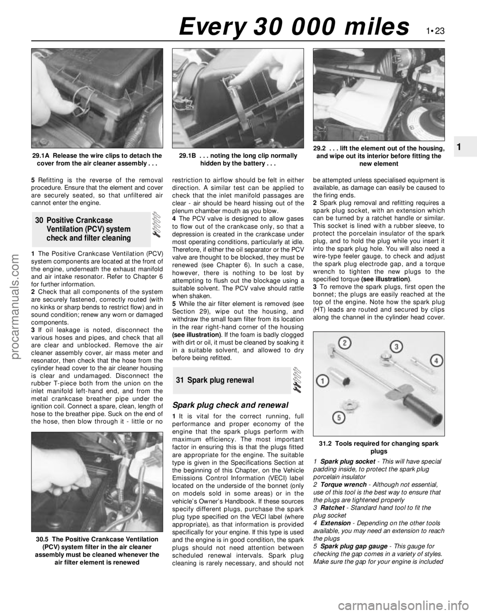
5Refitting is the reverse of the removal
procedure. Ensure that the element and cover
are securely seated, so that unfiltered air
cannot enter the engine.
1The Positive Crankcase Ventilation (PCV)
system components are located at the front of
the engine, underneath the exhaust manifold
and air intake resonator. Refer to Chapter 6
for further information.
2Check that all components of the system
are securely fastened, correctly routed (with
no kinks or sharp bends to restrict flow) and in
sound condition; renew any worn or damaged
components.
3If oil leakage is noted, disconnect the
various hoses and pipes, and check that all
are clear and unblocked. Remove the air
cleaner assembly cover, air mass meter and
resonator, then check that the hose from the
cylinder head cover to the air cleaner housing
is clear and undamaged. Disconnect the
rubber T-piece both from the union on the
inlet manifold left-hand end, and from the
metal crankcase breather pipe under the
ignition coil. Connect a spare, clean, length of
hose to the breather pipe. Suck on the end of
the hose, then blow through it - little or norestriction to airflow should be felt in either
direction. A similar test can be applied to
check that the inlet manifold passages are
clear - air should be heard hissing out of the
plenum chamber mouth as you blow.
4The PCV valve is designed to allow gases
to flow out of the crankcase only, so that a
depression is created in the crankcase under
most operating conditions, particularly at idle.
Therefore, if either the oil separator or the PCV
valve are thought to be blocked, they must be
renewed (see Chapter 6). In such a case,
however, there is nothing to be lost by
attempting to flush out the blockage using a
suitable solvent. The PCV valve should rattle
when shaken.
5While the air filter element is removed (see
Section 29), wipe out the housing, and
withdraw the small foam filter from its location
in the rear right-hand corner of the housing
(see illustration). If the foam is badly clogged
with dirt or oil, it must be cleaned by soaking it
in a suitable solvent, and allowed to dry
before being refitted.
Spark plug check and renewal
1It is vital for the correct running, full
performance and proper economy of the
engine that the spark plugs perform with
maximum efficiency. The most important
factor in ensuring this is that the plugs fitted
are appropriate for the engine. The suitable
type is given in the Specifications Section at
the beginning of this Chapter, on the Vehicle
Emissions Control Information (VECI) label
located on the underside of the bonnet (only
on models sold in some areas) or in the
vehicle’s Owner’s Handbook. If these sources
specify different plugs, purchase the spark
plug type specified on the VECI label (where
appropriate), as that information is provided
specifically for your engine. If this type is used
and the engine is in good condition, the spark
plugs should not need attention between
scheduled renewal intervals. Spark plug
cleaning is rarely necessary, and should notbe attempted unless specialised equipment is
available, as damage can easily be caused to
the firing ends.
2Spark plug removal and refitting requires a
spark plug socket, with an extension which
can be turned by a ratchet handle or similar.
This socket is lined with a rubber sleeve, to
protect the porcelain insulator of the spark
plug, and to hold the plug while you insert it
into the spark plug hole. You will also need a
wire-type feeler gauge, to check and adjust
the spark plug electrode gap, and a torque
wrench to tighten the new plugs to the
specified torque (see illustration).
3To remove the spark plugs, first open the
bonnet; the plugs are easily reached at the
top of the engine. Note how the spark plug
(HT) leads are routed and secured by clips
along the channel in the cylinder head cover.
31 Spark plug renewal
30 Positive Crankcase
Ventilation (PCV) system
check and filter cleaning
1•23
1
30.5 The Positive Crankcase Ventilation
(PCV) system filter in the air cleaner
assembly must be cleaned whenever the
air filter element is renewed
31.2 Tools required for changing spark
plugs
1Spark plug socket- This will have special
padding inside, to protect the spark plug
porcelain insulator
2Torque wrench- Although not essential,
use of this tool is the best way to ensure that
the plugs are tightened properly
3Ratchet- Standard hand tool to fit the
plug socket
4Extension- Depending on the other tools
available, you may need an extension to reach
the plugs
5Spark plug gap gauge- This gauge for
checking the gap comes in a variety of styles.
Make sure the gap for your engine is included
29.1A Release the wire clips to detach the
cover from the air cleaner assembly . . .29.1B . . . noting the long clip normally
hidden by the battery . . .29.2 . . . lift the element out of the housing,
and wipe out its interior before fitting the
new element
Every 30 000 miles
procarmanuals.com
Page 45 of 279
The cylinder head is provided with two oil
galleries, one on the inlet side and one on the
exhaust, to ensure constant oil supply to the
camshaft bearings and hydraulic tappets. A
retaining valve (inserted into the cylinder
head’s top surface, in the middle, on the inlet
side) prevents these galleries from being
drained when the engine is switched off. The
valve incorporates a ventilation hole in its
upper end, to allow air bubbles to escape
from the system when the engine is restarted.
While the crankshaft and camshaft
bearings and the hydraulic tappets receive a
pressurised supply, the camshaft lobes and
valves are lubricated by splash, as are all
other engine components.
Valve clearances - general
It is necessary for a clearance to exist
between the tip of each valve stem and the
valve operating mechanism, to allow for the
expansion of the various components as the
engine reaches normal operating
temperature.
On most older engine designs, this meant
that the valve clearances (also known as
“tappet” clearances) had to be checked and
adjusted regularly. If the clearances were
allowed to be too slack, the engine would be
very noisy, its power output would suffer, and
its fuel consumption would increase. If the
clearances were allowed to be too tight, the
engine’s power output would be reduced,
and the valves and their seats could be
severely damaged.
The engines covered in this manual,
however, employ hydraulic tappets which use
the lubricating system’s oil pressure
automatically to take up the clearance
between each camshaft lobe and its
respective valve stem. Therefore, there is no
need for regular checking and adjustment of
the valve clearances, but it is essential that
onlygood-quality oil of the recommended
viscosity and specification is used in the
engine, and that this oil is always changed at
the recommended intervals. If this advice is
not followed, the oilways and tappets may
become clogged with particles of dirt, or
deposits of burnt (inferior) engine oil, so that
the system cannot work properly; ultimately,
one or more of the tappets may fail, and
expensive repairs may be required.
On starting the engine from cold, there will
be a slight delay while full oil pressure builds
up in all parts of the engine, especially in the
tappets; the valve components, therefore,
may well “rattle” for about 10 seconds or so,
and then quieten. This is a normal state of
affairs, and is nothing to worry about,
provided that all tappets quieten quickly and
stay quiet.
After the vehicle has been standing for
several days, the valve components may
“rattle” for longer than usual, as nearly all the
oil will have drained away from the engine’s
top end components and bearing surfaces.
While this is only to be expected, care mustbe taken not to damage the engine under
these circumstances - avoid high speed
running until all the tappets are refilled with oil
and operating normally. With the vehicle
stationary, hold the engine at no more than a
fast idle speed (maximum 2000 to 2500 rpm)
for 10 to 15 seconds, or until the noise
ceases. Do not run the engine at more than
3000 rpm until the tappets are fully recharged
with oil and the noise has ceased.
If the valve components are thought to be
noisy, or if a light rattle persists from the top
end after the engine has warmed up to
normal operating temperature, take the
vehicle to a Ford dealer for expert advice.
Depending on the mileage covered and the
usage to which each vehicle has been put,
some vehicles may be noisier than others;
only a good mechanic experienced in these
engines can tell if the noise level is typical for
the vehicle’s mileage, or if a genuine fault
exists. If any tappet’s operation is faulty, it
must be renewed (Section 13).
The following major repair operations can
be accomplished without removing the
engine from the vehicle. However, owners
should note that any operation involving the
removal of the sump requires careful
forethought, depending on the level of skill
and the tools and facilities available; refer to
the relevant text for details.
(a) Compression pressure - testing.
(b) Cylinder head cover - removal and
refitting.
(c) Timing belt covers - removal and refitting.
(d) Timing belt - renewal.
(e) Timing belt tensioner and toothed pulleys
- removal and refitting.
(f) Camshaft oil seals - renewal.
(g) Camshafts and hydraulic tappets -
removal and refitting.
(h) Cylinder head - removal, overhaul and
refitting.
(i) Cylinder head and pistons -
decarbonising.
(j) Sump - removal and refitting.
(k) Crankshaft oil seals - renewal.
(l) Oil pump - removal and refitting.
(m) Piston/connecting rod assemblies -
removal and refitting (but see note below).
(n) Flywheel/driveplate - removal and
refitting.
(o) Engine/transmission mountings - removal
and refitting.
Clean the engine compartment and the
exterior of the engine with some type of
degreaser before any work is done. It will
make the job easier, and will help to keep dirt
out of the internal areas of the engine.
Depending on the components involved, it
may be helpful to remove the bonnet, to
improve access to the engine as repairs are
performed (refer to Chapter 11 if necessary).Cover the wings to prevent damage to the
paint; special covers are available, but an old
bedspread or blanket will also work.
If vacuum, exhaust, oil or coolant leaks
develop, indicating a need for component/
gasket or seal replacement, the repairs can
generally be made with the engine in the
vehicle. The intake and exhaust manifold
gaskets, sump gasket, crankshaft oil seals
and cylinder head gasket are all accessible
with the engine in place.
Exterior components such as the intake
and exhaust manifolds, the sump, the oil
pump, the water pump, the starter motor, the
alternator and the fuel system components
can be removed for repair with the engine in
place.
Since the cylinder head can be removed
without lifting out the engine, camshaft and
valve component servicing can also be
accomplished with the engine in the vehicle,
as can renewal of the timing belt and toothed
pulleys.
In extreme cases caused by a lack of
necessary equipment, repair or renewal of
piston rings, pistons, connecting rods and
big-end bearings is possible with the engine
in the vehicle. However, this practice is not
recommended, because of the cleaning and
preparation work that must be done to the
components involved, and because of the
amount of preliminary dismantling work
required - these operations are therefore
covered in Part B of this Chapter.
1When engine performance is down, or if
misfiring occurs which cannot be attributed to
the ignition or fuel systems, a compression
test can provide diagnostic clues as to the
engine’s condition. If the test is performed
regularly, it can give warning of trouble before
any other symptoms become apparent.
2The engine must be fully warmed-up to
normal operating temperature, the oil level
must be correct, the battery must be fully
charged, and the spark plugs must be
removed. The aid of an assistant will be
required also.
3Disable the ignition system by unplugging
the ignition coil’s electrical connector, and
remove fuse 14 to disconnect the fuel pump.
4Fit a compression tester to the No 1
cylinder spark plug hole - the type of tester
which screws into the plug thread is to be
preferred.
5Have the assistant hold the throttle wide
open and crank the engine on the starter
motor; after one or two revolutions, the
compression pressure should build up to a
maximum figure, and then stabilise. Record
the highest reading obtained.
6Repeat the test on the remaining cylinders,
recording the pressure developed in each.
7At the time of writing, no compression
3 Compression test -
description and interpretation
2 Repair operations possible with
the engine in the vehicle
In-car engine repair procedures 2A•5
2A
procarmanuals.com
Page 49 of 279
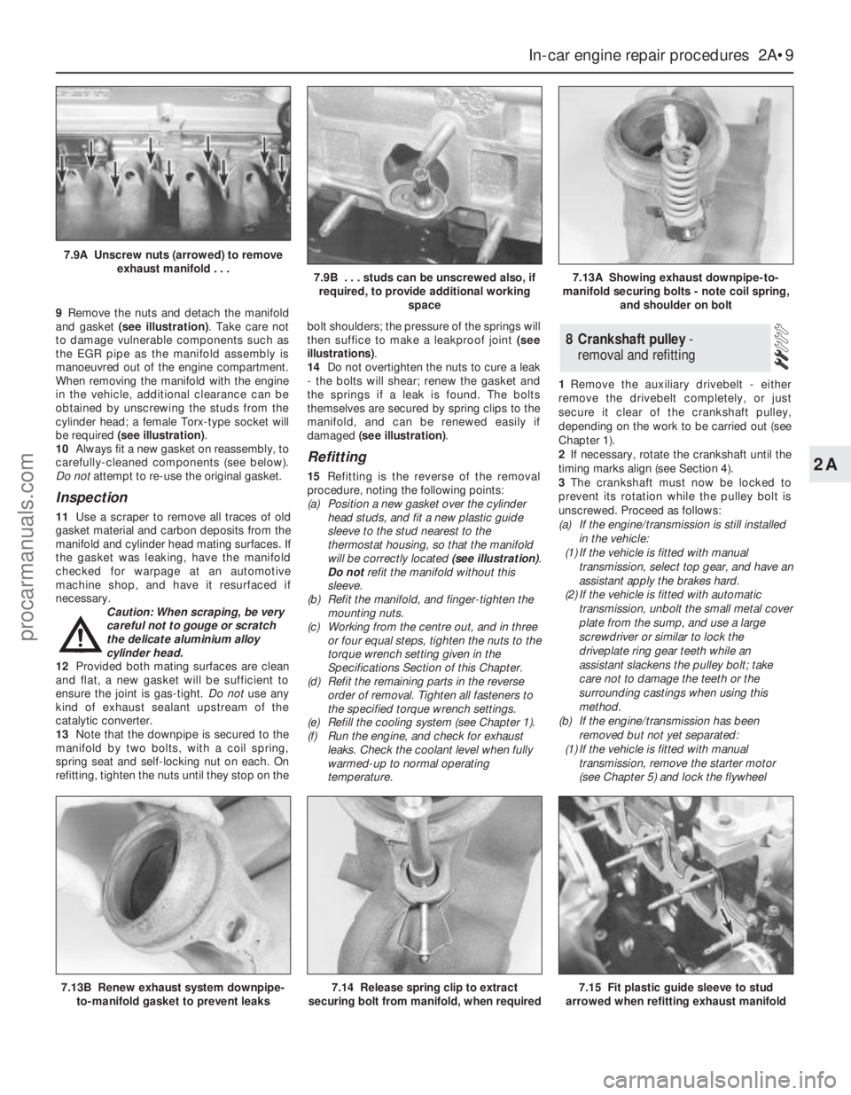
9Remove the nuts and detach the manifold
and gasket (see illustration). Take care not
to damage vulnerable components such as
the EGR pipe as the manifold assembly is
manoeuvred out of the engine compartment.
When removing the manifold with the engine
in the vehicle, additional clearance can be
obtained by unscrewing the studs from the
cylinder head; a female Torx-type socket will
be required (see illustration).
10Always fit a new gasket on reassembly, to
carefully-cleaned components (see below).
Do notattempt to re-use the original gasket.
Inspection
11Use a scraper to remove all traces of old
gasket material and carbon deposits from the
manifold and cylinder head mating surfaces. If
the gasket was leaking, have the manifold
checked for warpage at an automotive
machine shop, and have it resurfaced if
necessary.
Caution: When scraping, be very
careful not to gouge or scratch
the delicate aluminium alloy
cylinder head.
12Provided both mating surfaces are clean
and flat, a new gasket will be sufficient to
ensure the joint is gas-tight. Do notuse any
kind of exhaust sealant upstream of the
catalytic converter.
13Note that the downpipe is secured to the
manifold by two bolts, with a coil spring,
spring seat and self-locking nut on each. On
refitting, tighten the nuts until they stop on thebolt shoulders; the pressure of the springs will
then suffice to make a leakproof joint (see
illustrations).
14Do not overtighten the nuts to cure a leak
- the bolts will shear; renew the gasket and
the springs if a leak is found. The bolts
themselves are secured by spring clips to the
manifold, and can be renewed easily if
damaged (see illustration).
Refitting
15Refitting is the reverse of the removal
procedure, noting the following points:
(a) Position a new gasket over the cylinder
head studs, and fit a new plastic guide
sleeve to the stud nearest to the
thermostat housing, so that the manifold
will be correctly located (see illustration).
Do notrefit the manifold without this
sleeve.
(b) Refit the manifold, and finger-tighten the
mounting nuts.
(c) Working from the centre out, and in three
or four equal steps, tighten the nuts to the
torque wrench setting given in the
Specifications Section of this Chapter.
(d) Refit the remaining parts in the reverse
order of removal. Tighten all fasteners to
the specified torque wrench settings.
(e) Refill the cooling system (see Chapter 1).
(f) Run the engine, and check for exhaust
leaks. Check the coolant level when fully
warmed-up to normal operating
temperature.1Remove the auxiliary drivebelt - either
remove the drivebelt completely, or just
secure it clear of the crankshaft pulley,
depending on the work to be carried out (see
Chapter 1).
2If necessary, rotate the crankshaft until the
timing marks align (see Section 4).
3The crankshaft must now be locked to
prevent its rotation while the pulley bolt is
unscrewed. Proceed as follows:
(a) If the engine/transmission is still installed
in the vehicle:
(1) If the vehicle is fitted with manual
transmission, select top gear, and have an
assistant apply the brakes hard.
(2) If the vehicle is fitted with automatic
transmission, unbolt the small metal cover
plate from the sump, and use a large
screwdriver or similar to lock the
driveplate ring gear teeth while an
assistant slackens the pulley bolt; take
care not to damage the teeth or the
surrounding castings when using this
method.
(b) If the engine/transmission has been
removed but not yet separated:
(1) If the vehicle is fitted with manual
transmission, remove the starter motor
(see Chapter 5) and lock the flywheel
8 Crankshaft pulley -
removal and refitting
In-car engine repair procedures 2A•9
2A
7.13B Renew exhaust system downpipe-
to-manifold gasket to prevent leaks7.14 Release spring clip to extract
securing bolt from manifold, when required7.15 Fit plastic guide sleeve to stud
arrowed when refitting exhaust manifold
7.9A Unscrew nuts (arrowed) to remove
exhaust manifold . . .
7.9B . . . studs can be unscrewed also, if
required, to provide additional working
space7.13A Showing exhaust downpipe-to-
manifold securing bolts - note coil spring,
and shoulder on bolt
procarmanuals.com