1993 FORD MONDEO ground clearance
[x] Cancel search: ground clearancePage 30 of 279
comb” or compressed air to clean the
condenser.
Warning: Wear eye protection
when using compressed air!
(d) Check that the drain tube from the front
of the evaporator is clear - note that it is
normal to have clear fluid (water) dripping
from this while the system is in operation,
to the extent that quite a large puddle can
be left under the vehicle when it is parked.
2It’s a good idea to operate the system forabout 30 minutes at least once a month,
particularly during the winter. Long term
non-use can cause hardening, and
subsequent failure, of the seals.
3Because of the complexity of the air
conditioning system and the special
equipment necessary to service it, in-depth
fault diagnosis and repairs are not included in
this manual. For more complete information
on the air conditioning system, refer to the
Haynes Automotive Heating and Air
Conditioning Manual.
4The most common cause of poor cooling is
simply a low system refrigerant charge. If a
noticeable drop in cool air output occurs, the
following quick check will help you determine
if the refrigerant level is low.
5Warm the engine up to normal operating
temperature.
6Place the air conditioning temperature
selector at the coldest setting, and put the
blower at the highest setting. Open the doors
- to make sure the air conditioning system
doesn’t cycle off as soon as it cools the
passenger compartment.
7With the compressor engaged - the clutch
will make an audible click, and the centre of
the clutch will rotate - feel the inlet and outlet
pipes at the compressor. One side should be
cold, and one hot. If there’s no perceptible
difference between the two pipes, there’s
something wrong with the compressor or the
system. It might be a low charge - it might be
something else. Take the vehicle to a dealer
service department or an automotive air
conditioning specialist.1Make sure that you have all the necessary
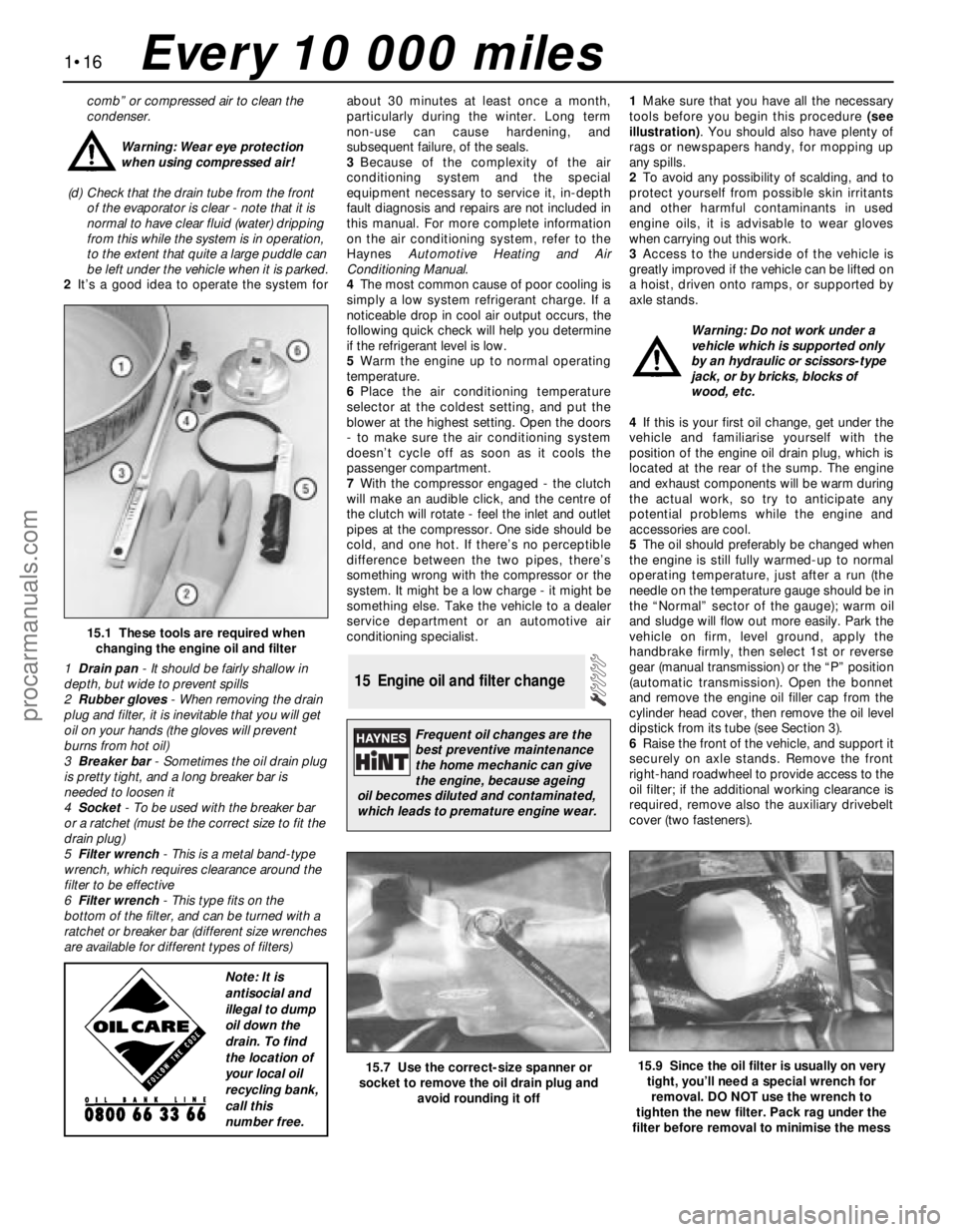
tools before you begin this procedure (see
illustration). You should also have plenty of
rags or newspapers handy, for mopping up
any spills.
2To avoid any possibility of scalding, and to
protect yourself from possible skin irritants
and other harmful contaminants in used
engine oils, it is advisable to wear gloves
when carrying out this work.
3Access to the underside of the vehicle is
greatly improved if the vehicle can be lifted on
a hoist, driven onto ramps, or supported by
axle stands.
Warning: Do not work under a
vehicle which is supported only
by an hydraulic or scissors-type
jack, or by bricks, blocks of
wood, etc.
4If this is your first oil change, get under the
vehicle and familiarise yourself with the
position of the engine oil drain plug, which is
located at the rear of the sump. The engine
and exhaust components will be warm during
the actual work, so try to anticipate any
potential problems while the engine and
accessories are cool.
5The oil should preferably be changed when
the engine is still fully warmed-up to normal
operating temperature, just after a run (the
needle on the temperature gauge should be in
the “Normal” sector of the gauge); warm oil
and sludge will flow out more easily. Park the
vehicle on firm, level ground, apply the
handbrake firmly, then select 1st or reverse
gear (manual transmission) or the “P” position
(automatic transmission). Open the bonnet
and remove the engine oil filler cap from the
cylinder head cover, then remove the oil level
dipstick from its tube (see Section 3).
6Raise the front of the vehicle, and support it
securely on axle stands. Remove the front
right-hand roadwheel to provide access to the
oil filter; if the additional working clearance is
required, remove also the auxiliary drivebelt
cover (two fasteners).
15 Engine oil and filter change
1•16
15.1 These tools are required when
changing the engine oil and filter
1Drain pan- It should be fairly shallow in
depth, but wide to prevent spills
2Rubber gloves- When removing the drain
plug and filter, it is inevitable that you will get
oil on your hands (the gloves will prevent
burns from hot oil)
3Breaker bar- Sometimes the oil drain plug
is pretty tight, and a long breaker bar is
needed to loosen it
4Socket- To be used with the breaker bar
or a ratchet (must be the correct size to fit the
drain plug)
5Filter wrench- This is a metal band-type
wrench, which requires clearance around the
filter to be effective
6Filter wrench- This type fits on the
bottom of the filter, and can be turned with a
ratchet or breaker bar (different size wrenches
are available for different types of filters)
15.7 Use the correct-size spanner or
socket to remove the oil drain plug and
avoid rounding it off15.9 Since the oil filter is usually on very
tight, you’ll need a special wrench for
removal. DO NOT use the wrench to
tighten the new filter. Pack rag under the
filter before removal to minimise the mess
Every 10 000 miles
Frequent oil changes are the
best preventive maintenance
the home mechanic can give
the engine, because ageing
oil becomes diluted and contaminated,
which leads to premature engine wear.
Note: It is
antisocial and
illegal to dump
oil down the
drain. To find
the location of
your local oil
recycling bank,
call this
number free.
procarmanuals.com
Page 36 of 279
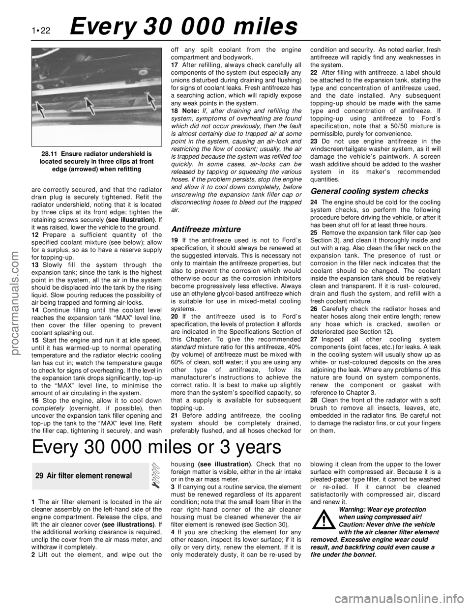
are correctly secured, and that the radiator
drain plug is securely tightened. Refit the
radiator undershield, noting that it is located
by three clips at its front edge; tighten the
retaining screws securely (see illustration). If
it was raised, lower the vehicle to the ground.
12Prepare a sufficient quantity of the
specified coolant mixture (see below); allow
for a surplus, so as to have a reserve supply
for topping-up.
13Slowly fill the system through the
expansion tank; since the tank is the highest
point in the system, all the air in the system
should be displaced into the tank by the rising
liquid. Slow pouring reduces the possibility of
air being trapped and forming air-locks.
14Continue filling until the coolant level
reaches the expansion tank “MAX” level line,
then cover the filler opening to prevent
coolant splashing out.
15Start the engine and run it at idle speed,
until it has warmed-up to normal operating
temperature and the radiator electric cooling
fan has cut in; watch the temperature gauge
to check for signs of overheating. If the level in
the expansion tank drops significantly, top-up
to the “MAX” level line, to minimise the
amount of air circulating in the system.
16Stop the engine, allow it to cool down
completely(overnight, if possible), then
uncover the expansion tank filler opening and
top-up the tank to the “MAX” level line. Refit
the filler cap, tightening it securely, and washoff any spilt coolant from the engine
compartment and bodywork.
17After refilling, always check carefully all
components of the system (but especially any
unions disturbed during draining and flushing)
for signs of coolant leaks. Fresh antifreeze has
a searching action, which will rapidly expose
any weak points in the system.
18 Note:If, after draining and refilling the
system, symptoms of overheating are found
which did not occur previously, then the fault
is almost certainly due to trapped air at some
point in the system, causing an air-lock and
restricting the flow of coolant; usually, the air
is trapped because the system was refilled too
quickly. In some cases, air-locks can be
released by tapping or squeezing the various
hoses. If the problem persists, stop the engine
and allow it to cool down completely, before
unscrewing the expansion tank filler cap or
disconnecting hoses to bleed out the trapped
air.
Antifreeze mixture
19If the antifreeze used is not to Ford’s
specification, it should always be renewed at
the suggested intervals. This is necessary not
only to maintain the antifreeze properties, but
also to prevent the corrosion which would
otherwise occur as the corrosion inhibitors
become progressively less effective. Always
use an ethylene glycol-based antifreeze which
is suitable for use in mixed-metal cooling
systems.
20If the antifreeze used is to Ford’s
specification, the levels of protection it affords
are indicated in the Specifications Section of
this Chapter. To give the recommended
standardmixture ratio for this antifreeze, 40%
(by volume) of antifreeze must be mixed with
60% of clean, soft water; if you are using any
other type of antifreeze, follow its
manufacturer’s instructions to achieve the
correct ratio. It is best to make up slightly
more than the system’s specified capacity, so
that a supply is available for subsequent
topping-up.
21Before adding antifreeze, the cooling
system should be completely drained,
preferably flushed, and all hoses checked forcondition and security. As noted earlier, fresh
antifreeze will rapidly find any weaknesses in
the system.
22After filling with antifreeze, a label should
be attached to the expansion tank, stating the
type and concentration of antifreeze used,
and the date installed. Any subsequent
topping-up should be made with the same
type and concentration of antifreeze. If
topping-up using antifreeze to Ford’s
specification, note that a 50/50 mixture is
permissible, purely for convenience.
23Do not use engine antifreeze in the
windscreen/tailgate washer system, as it will
damage the vehicle’s paintwork. A screen
wash additive should be added to the washer
system in its maker’s recommended
quantities.
General cooling system checks
24The engine should be cold for the cooling
system checks, so perform the following
procedure before driving the vehicle, or after it
has been shut off for at least three hours.
25Remove the expansion tank filler cap (see
Section 3), and clean it thoroughly inside and
out with a rag. Also clean the filler neck on the
expansion tank. The presence of rust or
corrosion in the filler neck indicates that the
coolant should be changed. The coolant
inside the expansion tank should be relatively
clean and transparent. If it is rust- coloured,
drain and flush the system, and refill with a
fresh coolant mixture.
26Carefully check the radiator hoses and
heater hoses along their entire length; renew
any hose which is cracked, swollen or
deteriorated (see Section 12).
27Inspect all other cooling system
components (joint faces, etc.) for leaks. A leak
in the cooling system will usually show up as
white- or rust-coloured deposits on the area
adjoining the leak. Where any problems of this
nature are found on system components,
renew the component or gasket with
reference to Chapter 3.
28Clean the front of the radiator with a soft
brush to remove all insects, leaves, etc,
embedded in the radiator fins. Be careful not
to damage the radiator fins, or cut your fingers
on them.
1•22
28.11 Ensure radiator undershield is
located securely in three clips at front
edge (arrowed) when refitting
Every 30 000 miles
Every 30 000 miles or 3 years
1The air filter element is located in the air
cleaner assembly on the left-hand side of the
engine compartment. Release the clips, and
lift the air cleaner cover (see illustrations). If
the additional working clearance is required,
unclip the cover from the air mass meter, and
withdraw it completely.
2Lift out the element, and wipe out thehousing (see illustration). Check that no
foreign matter is visible, either in the air intake
or in the air mass meter.
3If carrying out a routine service, the element
must be renewed regardless of its apparent
condition; note that the small foam filter in the
rear right-hand corner of the air cleaner
housing must be cleaned whenever the air
filter element is renewed (see Section 30).
4If you are checking the element for any
other reason, inspect its lower surface; if it is
oily or very dirty, renew the element. If it is
only moderately dusty, it can be re-used byblowing it clean from the upper to the lower
surface with compressed air. Because it is a
pleated-paper type filter, it cannot be washed
or re-oiled. If it cannot be cleaned
satisfactorily with compressed air, discard
and renew it.
Warning: Wear eye protection
when using compressed air!
Caution: Never drive the vehicle
with the air cleaner filter element
removed. Excessive engine wear could
result, and backfiring could even cause a
fire under the bonnet.
29 Air filter element renewal
procarmanuals.com
Page 77 of 279
4Scrape off any heavy carbon deposits that
may have formed on the valves, then use a
power-operated wire brush to remove
deposits from the valve heads and stems.
Inspection
Note:Be sure to perform all the following
inspection procedures before concluding that
the services of a machine shop or engine
overhaul specialist are required. Make a list of
all items that require attention.
Cylinder head
5Inspect the head very carefully for cracks,
evidence of coolant leakage, and other
damage. If cracks are found, a new cylinder
head should be obtained.
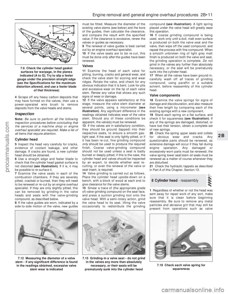
6Use a straight edge and feeler blade to
check that the cylinder head gasket surface is
not distorted (see illustration). If it is, it may
be possible to re-surface it.
7Examine the valve seats in each of the
combustion chambers. If they are severely
pitted, cracked or burned, then they will need
to be renewed or re-cut by an engine overhaul
specialist. If they are only slightly pitted, this
can be removed by grinding-in the valve
heads and seats with fine valve-grinding
compound, as described below.
8If the valve guides are worn, indicated by a
side-to-side motion of the valve, new guidesmust be fitted. Measure the diameter of the
existing valve stems (see below) and the bore
of the guides, then calculate the clearance,
and compare the result with the specified
value; if the clearance is excessive, renew the
valves or guides as necessary.
9The renewal of valve guides is best carried
out by an engine overhaul specialist.
10If the valve seats are to be re-cut, this
must be done only afterthe guides have been
renewed.
Valves
11Examine the head of each valve for
pitting, burning, cracks and general wear, and
check the valve stem for scoring and wear
ridges. Rotate the valve, and check for any
obvious indication that it is bent. Look for pits
and excessive wear on the tip of each valve
stem. Renew any valve that shows any such
signs of wear or damage.
12If the valve appears satisfactory at this
stage, measure the valve stem diameter at
several points, using a micrometer (see
illustration). Any significant difference in the
readings obtained indicates wear of the valve
stem. Should any of these conditions be
apparent, the valve(s) must be renewed.
13If the valves are in satisfactory condition,
they should be ground (lapped) into their
respective seats, to ensure a smooth gas-
tight seal. If the seat is only lightly pitted, or if
it has been re-cut, fine grinding compound
onlyshould be used to produce the required
finish. Coarse valve-grinding compound
should notbe used unless a seat is badly
burned or deeply pitted; if this is the case, the
cylinder head and valves should be inspected
by an expert, to decide whether seat re-
cutting, or even the renewal of the valve or
seat insert, is required.
14Valve grinding is carried out as follows.
Place the cylinder head upside-down on a
bench, with a block of wood at each end to
give clearance for the valve stems.
15Smear a trace of (the appropriate grade
of) valve-grinding compound on the seat face,
and press a suction grinding tool onto the
valve head. With a semi-rotary action, grind
the valve head to its seat, lifting the valve
occasionally to redistribute the grindingcompound (see illustration). A light spring
placed under the valve head will greatly ease
this operation.
16If coarse grinding compound is being
used, work only until a dull, matt even surface
is produced on both the valve seat and the
valve, then wipe off the used compound, and
repeat the process with fine compound. When
a smooth unbroken ring of light grey matt
finish is produced on both the valve and seat,
the grinding operation is complete. Do not
grind in the valves any further than absolutely
necessary, or the seat will be prematurely
sunk into the cylinder head.
17When all the valves have been ground-in,
carefully wash off alltraces of grinding
compound, using paraffin or a suitable
solvent, before reassembly of the cylinder
head.
Valve components
18Examine the valve springs for signs of
damage and discolouration, and also measure
their free length by comparing each of the
existing springs with a new component.
19Stand each spring on a flat surface, and
check it for squareness (see illustration). If
any of the springs are damaged, distorted, or
have lost their tension, obtain a complete set
of new springs.
20Check the spring upper seats and collets
for obvious wear and cracks. Any
questionable parts should be renewed, as
extensive damage will occur if they fail during
engine operation. Any damaged or
excessively-worn parts must be renewed; the
valve spring lower seat/stem oil seals must be
renewed as a matter of course whenever they
are disturbed.
21Check the hydraulic tappets as described
in Part A of this Chapter, Section 13.
1Regardless of whether or not the head was
sent away for repair work of any sort, make
sure that it is clean before beginning
reassembly. Be sure to remove any metal
particles and abrasive grit that may still be
present from operations such as valve
8 Cylinder head - reassembly
Engine removal and general engine overhaul procedures 2B•11
2B
7.12 Measuring the diameter of a valve
stem - if any significant difference is found
in the readings obtained, excessive valve
stem wear is indicated7.15 Grinding-in a valve seat - do not grind
in the valves any more than absolutely
necessary, or their seats will be
prematurely sunk into the cylinder head
7.19 Check each valve spring for
squareness
7.6 Check the cylinder head gasket
surfaces for warpage, in the planes
indicated (A to G). Try to slip a feeler
gauge under the precision straight edge
(see the Specifications for the maximum
distortion allowed, and use a feeler blade
of that thickness)
procarmanuals.com
Page 84 of 279
Note:Always check first what replacement
parts are available before planning any
overhaul operation; refer to Section 1 of this
Part. A Ford dealer, or a good engine
reconditioning specialist/automotive parts
supplier, may be able to suggest alternatives
which will enable you to overcome the lack of
replacement parts.
1Clean the crankshaft, and dry it with
compressed air if available.
Warning: Wear eye protection
when using compressed air! Be
sure to clean the oil holes with a
pipe cleaner or similar probe.
2Check the main and crankpin (big-end)
bearing journals for uneven wear, scoring,
pitting and cracking.
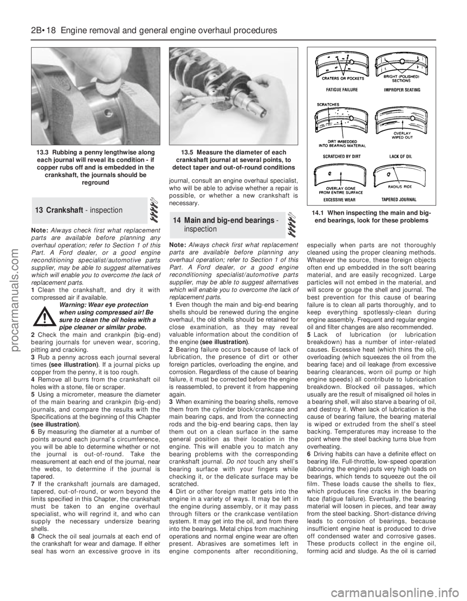
3Rub a penny across each journal several
times (see illustration). If a journal picks up
copper from the penny, it is too rough.
4Remove all burrs from the crankshaft oil
holes with a stone, file or scraper.
5Using a micrometer, measure the diameter
of the main bearing and crankpin (big-end)
journals, and compare the results with the
Specifications at the beginning of this Chapter
(see illustration).
6By measuring the diameter at a number of
points around each journal’s circumference,
you will be able to determine whether or not
the journal is out-of-round. Take the
measurement at each end of the journal, near
the webs, to determine if the journal is
tapered.
7If the crankshaft journals are damaged,
tapered, out-of-round, or worn beyond the
limits specified in this Chapter, the crankshaft
must be taken to an engine overhaul
specialist, who will regrind it, and who can
supply the necessary undersize bearing
shells.
8Check the oil seal journals at each end of
the crankshaft for wear and damage. If either
seal has worn an excessive groove in itsjournal, consult an engine overhaul specialist,
who will be able to advise whether a repair is
possible, or whether a new crankshaft is
necessary.
Note:Always check first what replacement
parts are available before planning any
overhaul operation; refer to Section 1 of this
Part. A Ford dealer, or a good engine
reconditioning specialist/automotive parts
supplier, may be able to suggest alternatives
which will enable you to overcome the lack of
replacement parts.
1Even though the main and big-end bearing
shells should be renewed during the engine
overhaul, the old shells should be retained for
close examination, as they may reveal
valuable information about the condition of
the engine (see illustration).
2Bearing failure occurs because of lack of
lubrication, the presence of dirt or other
foreign particles, overloading the engine, and
corrosion. Regardless of the cause of bearing
failure, it must be corrected before the engine
is reassembled, to prevent it from happening
again.
3When examining the bearing shells, remove
them from the cylinder block/crankcase and
main bearing caps, and from the connecting
rods and the big-end bearing caps, then lay
them out on a clean surface in the same
general position as their location in the
engine. This will enable you to match any
bearing problems with the corresponding
crankshaft journal. Do nottouch any shell’s
bearing surface with your fingers while
checking it, or the delicate surface may be
scratched.
4Dirt or other foreign matter gets into the
engine in a variety of ways. It may be left in
the engine during assembly, or it may pass
through filters or the crankcase ventilation
system. It may get into the oil, and from there
into the bearings. Metal chips from machining
operations and normal engine wear are often
present. Abrasives are sometimes left in
engine components after reconditioning,especially when parts are not thoroughly
cleaned using the proper cleaning methods.
Whatever the source, these foreign objects
often end up embedded in the soft bearing
material, and are easily recognized. Large
particles will not embed in the material, and
will score or gouge the shell and journal. The
best prevention for this cause of bearing
failure is to clean all parts thoroughly, and to
keep everything spotlessly-clean during
engine assembly. Frequent and regular engine
oil and filter changes are also recommended.
5Lack of lubrication (or lubrication
breakdown) has a number of inter-related
causes. Excessive heat (which thins the oil),
overloading (which squeezes the oil from the
bearing face) and oil leakage (from excessive
bearing clearances, worn oil pump or high
engine speeds) all contribute to lubrication
breakdown. Blocked oil passages, which
usually are the result of misaligned oil holes in
a bearing shell, will also starve a bearing of oil,
and destroy it. When lack of lubrication is the
cause of bearing failure, the bearing material
is wiped or extruded from the shell’s steel
backing. Temperatures may increase to the
point where the steel backing turns blue from
overheating.
6Driving habits can have a definite effect on
bearing life. Full-throttle, low-speed operation
(labouring the engine) puts very high loads on
bearings, which tends to squeeze out the oil
film. These loads cause the shells to flex,
which produces fine cracks in the bearing
face (fatigue failure). Eventually, the bearing
material will loosen in pieces, and tear away
from the steel backing. Short-distance driving
leads to corrosion of bearings, because
insufficient engine heat is produced to drive
off condensed water and corrosive gases.
These products collect in the engine oil,
forming acid and sludge. As the oil is carried
14 Main and big-end bearings-
inspection
13 Crankshaft - inspection
2B•18 Engine removal and general engine overhaul procedures
13.3 Rubbing a penny lengthwise along
each journal will reveal its condition - if
copper rubs off and is embedded in the
crankshaft, the journals should be
reground13.5 Measure the diameter of each
crankshaft journal at several points, to
detect taper and out-of-round conditions
14.1 When inspecting the main and big-
end bearings, look for these problems
procarmanuals.com
Page 86 of 279
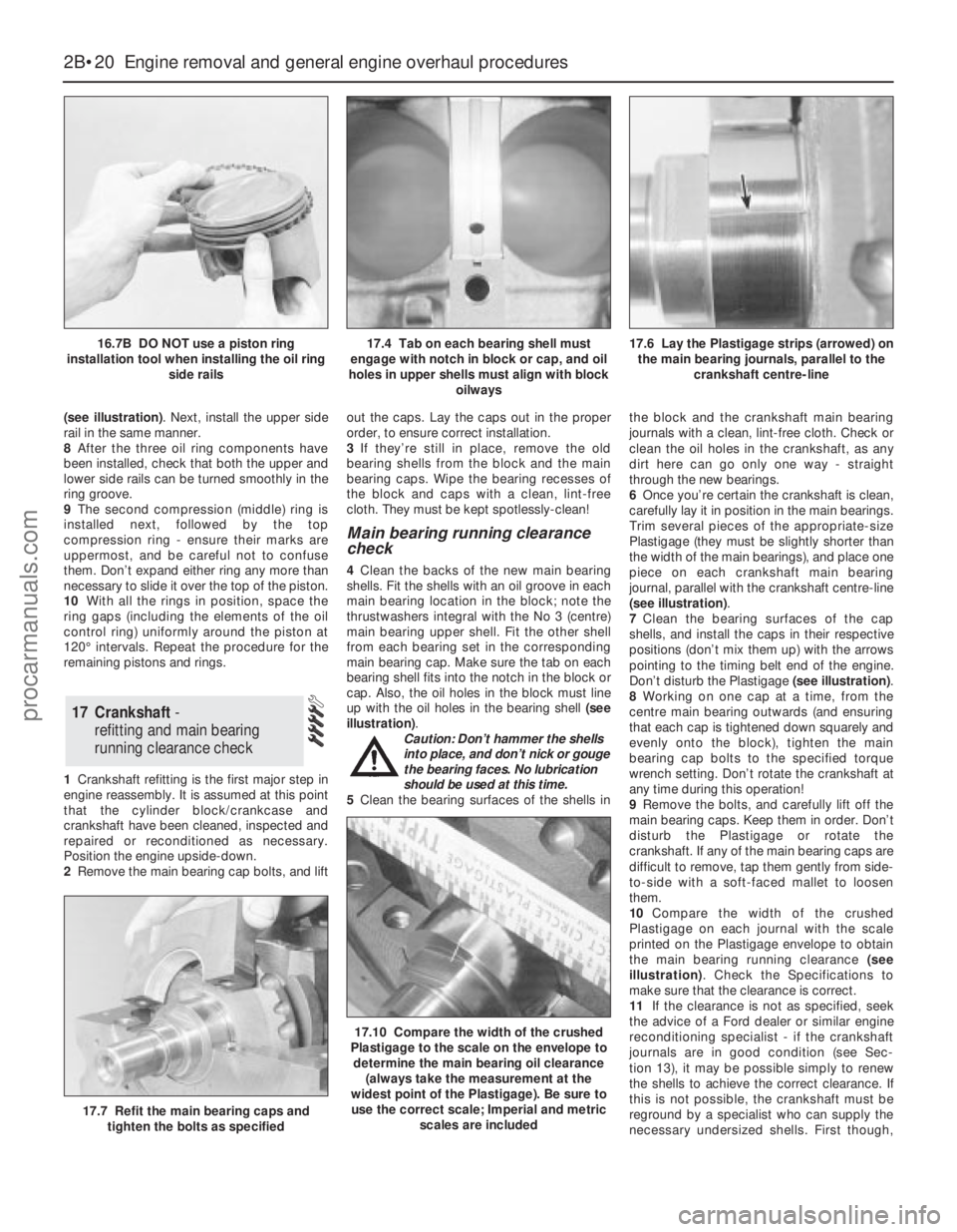
(see illustration). Next, install the upper side
rail in the same manner.
8After the three oil ring components have
been installed, check that both the upper and
lower side rails can be turned smoothly in the
ring groove.
9The second compression (middle) ring is
installed next, followed by the top
compression ring - ensure their marks are
uppermost, and be careful not to confuse
them. Don’t expand either ring any more than
necessary to slide it over the top of the piston.
10With all the rings in position, space the
ring gaps (including the elements of the oil
control ring) uniformly around the piston at
120° intervals. Repeat the procedure for the
remaining pistons and rings.
1Crankshaft refitting is the first major step in
engine reassembly. It is assumed at this point
that the cylinder block/crankcase and
crankshaft have been cleaned, inspected and
repaired or reconditioned as necessary.
Position the engine upside-down.
2Remove the main bearing cap bolts, and liftout the caps. Lay the caps out in the proper
order, to ensure correct installation.
3If they’re still in place, remove the old
bearing shells from the block and the main
bearing caps. Wipe the bearing recesses of
the block and caps with a clean, lint-free
cloth. They must be kept spotlessly-clean!
Main bearing running clearance
check
4Clean the backs of the new main bearing
shells. Fit the shells with an oil groove in each
main bearing location in the block; note the
thrustwashers integral with the No 3 (centre)
main bearing upper shell. Fit the other shell
from each bearing set in the corresponding
main bearing cap. Make sure the tab on each
bearing shell fits into the notch in the block or
cap. Also, the oil holes in the block must line
up with the oil holes in the bearing shell (see
illustration).
Caution: Don’t hammer the shells
into place, and don’t nick or gouge
the bearing faces. No lubrication
should be used at this time.
5Clean the bearing surfaces of the shells inthe block and the crankshaft main bearing
journals with a clean, lint-free cloth. Check or
clean the oil holes in the crankshaft, as any
dirt here can go only one way - straight
through the new bearings.
6Once you’re certain the crankshaft is clean,
carefully lay it in position in the main bearings.
Trim several pieces of the appropriate-size
Plastigage (they must be slightly shorter than
the width of the main bearings), and place one
piece on each crankshaft main bearing
journal, parallel with the crankshaft centre-line
(see illustration).
7Clean the bearing surfaces of the cap
shells, and install the caps in their respective
positions (don’t mix them up) with the arrows
pointing to the timing belt end of the engine.
Don’t disturb the Plastigage (see illustration).
8Working on one cap at a time, from the
centre main bearing outwards (and ensuring
that each cap is tightened down squarely and
evenly onto the block), tighten the main
bearing cap bolts to the specified torque
wrench setting. Don’t rotate the crankshaft at
any time during this operation!
9Remove the bolts, and carefully lift off the
main bearing caps. Keep them in order. Don’t
disturb the Plastigage or rotate the
crankshaft. If any of the main bearing caps are
difficult to remove, tap them gently from side-
to-side with a soft-faced mallet to loosen
them.
10Compare the width of the crushed
Plastigage on each journal with the scale
printed on the Plastigage envelope to obtain
the main bearing running clearance (see
illustration). Check the Specifications to
make sure that the clearance is correct.
11If the clearance is not as specified, seek
the advice of a Ford dealer or similar engine
reconditioning specialist - if the crankshaft
journals are in good condition (see Sec-
tion 13), it may be possible simply to renew
the shells to achieve the correct clearance. If
this is not possible, the crankshaft must be
reground by a specialist who can supply the
necessary undersized shells. First though,
17 Crankshaft-
refitting and main bearing
running clearance check
2B•20 Engine removal and general engine overhaul procedures
16.7B DO NOT use a piston ring
installation tool when installing the oil ring
side rails17.4 Tab on each bearing shell must
engage with notch in block or cap, and oil
holes in upper shells must align with block
oilways17.6 Lay the Plastigage strips (arrowed) on
the main bearing journals, parallel to the
crankshaft centre-line
17.7 Refit the main bearing caps and
tighten the bolts as specified
17.10 Compare the width of the crushed
Plastigage to the scale on the envelope to
determine the main bearing oil clearance
(always take the measurement at the
widest point of the Plastigage). Be sure to
use the correct scale; Imperial and metric
scales are included
procarmanuals.com
Page 88 of 279
rod’s big-end onto the crankpin. The piston
rings may try to pop out of the ring
compressor just before entering the cylinder
bore, so keep some pressure on the ring
compressor. Work slowly, and if any
resistance is felt as the piston enters the
cylinder, stop immediately. Find out what’s
binding, and fix it before proceeding. Do not,
for any reason, force the piston into the
cylinder - you might break a ring and/or the
piston.
10To check the big-end bearing running
clearance, cut a piece of the appropriate-size
Plastigage slightly shorter than the width of
the connecting rod bearing, and lay it in place
on the No 1 crankpin (big-end) journal, parallel
with the crankshaft centre-line (see illus-
tration 17.6).
11Clean the connecting rod-to-cap mating
surfaces, and refit the big-end bearing cap.
Make sure the etched number on the cap is
on the same side as that on the rod (see
illustration). Tighten the cap bolts evenly -
first use a torque wrench to tighten the bolts
to the specified (first stage) torque setting,
then use an ordinary socket extension bar
and an angle gauge to tighten the bolts
further through the specified (second stage)
angle. Use a thin-wall socket, to avoid
erroneous torque readings that can result if
the socket is wedged between the cap and
nut. If the socket tends to wedge itself
between the nut and the cap, lift up on it
slightly until it no longer contacts the cap.
Don’t rotate the crankshaft at any time during
this operation!
12Unscrew the bolts and detach the cap,
being very careful not to disturb the
Plastigage.
13Compare the width of the crushed
Plastigage to the scale printed on the
Plastigage envelope, to obtain the running
clearance (see illustration 17.10). Compare it
to the Specifications, to make sure the
clearance is correct.
14If the clearance is not as specified, seek
the advice of a Ford dealer or similar engine
reconditioning specialist - if the crankshaft
journals are in good condition (see Sec-
tion 13), it may be possible simply to renew
the shells to achieve the correct clearance. If
this is not possible, the crankshaft must bereground by a specialist, who can also supply
the necessary undersized shells. First though,
make sure that no dirt or oil was trapped
between the bearing shells and the
connecting rod or cap when the clearance
was measured. Also, recheck the crankpin
diameter. If the Plastigage was wider at one
end than the other, the crankpin journal may
be tapered (see Section 13).
15Carefully scrape all traces of the
Plastigage material off the journal and the
bearing surface. Be very careful not to scratch
the bearing - use your fingernail or the edge of
a credit card.
Final piston/connecting rod
refitting
16Make sure the bearing surfaces are
perfectly clean, then apply a uniform layer of
clean molybdenum disulphide-based grease,
engine assembly lubricant, or clean engine oil,
to both of them. You’ll have to push the piston
into the cylinder to expose the bearing surface
of the shell in the connecting rod.
17Slide the connecting rod back into place
on the crankpin (big-end) journal, refit the big-
end bearing cap, and then tighten the bolts in
two stages, as described above.
18Repeat the entire procedure for the
remaining piston/connecting rod assemblies.
19The important points to remember are:
(a) Keep the backs of the bearing shells and
the recesses of the connecting rods and
caps perfectly clean when assembling
them.
(b) Make sure you have the correct
piston/rod assembly for each cylinder -
use the etched cylinder numbers to
identify the front-facing side of both the
rod and its cap.
(c) The arrow on the piston crown must face
the timing belt end of the engine.
(d) Lubricate the cylinder bores with clean
engine oil.
(e) Lubricate the bearing surfaces when
refitting the big-end bearing caps after the
running clearance has been checked.
20After all the piston/connecting rod
assemblies have been properly installed,
rotate the crankshaft a number of times by
hand, to check for any obvious binding.1With the engine refitted in the vehicle,
double-check the engine oil and coolant
levels. Make a final check that everything has
been reconnected, and that there are no tools
or rags left in the engine compartment.
2With the spark plugs removed and the
ignition system disabled by unplugging the
ignition coil’s electrical connector, remove
fuse 14 to disconnect the fuel pump. Turn the
engine on the starter until the oil pressure
warning light goes out.
3Refit the spark plugs, and connect all the
spark plug (HT) leads (Chapter 1). Reconnect
the ignition coil wiring, refit the fuel pump fuse,
then switch on the ignition and listen for the fuel
pump; it will run for a little longer than usual,
due to the lack of pressure in the system.
4Start the engine, noting that this also may
take a little longer than usual, due to the fuel
system components being empty.
5While the engine is idling, check for fuel,
coolant and oil leaks. Don’t be alarmed if
there are some odd smells and smoke from
parts getting hot and burning off oil deposits.
If the hydraulic tappets have been disturbed,
some valve gear noise may be heard at first;
this should disappear as the oil circulates fully
around the engine, and normal pressure is
restored in the tappets.
6Keep the engine idling until hot water is felt
circulating through the top hose, check that it
idles reasonably smoothly and at the usual
speed, then switch it off.
7After a few minutes, recheck the oil and
coolant levels, and top-up as necessary
(Chapter 1).
8If they were tightened as described, there is
no need to re-tighten the cylinder head bolts
once the engine has first run after reassembly
- in fact, Ford state that the bolts must notbe
re-tightened.
9If new components such as pistons, rings
or crankshaft bearings have been fitted, the
engine must be run-in for the first 500 miles
(800 km). Do not operate the engine at full-
throttle, or allow it to labour in any gear during
this period. It is recommended that the oil and
filter be changed at the end of this period.
19 Engine -
initial start-up after overhaul
2B•22 Engine removal and general engine overhaul procedures
procarmanuals.com
Page 273 of 279
REF•14Glossary of Technical Terms
Catalytic converterA silencer-like device in
the exhaust system which converts certain
pollutants in the exhaust gases into less
harmful substances.
CirclipA ring-shaped clip used to prevent
endwise movement of cylindrical parts and
shafts. An internal circlip is installed in a
groove in a housing; an external circlip fits into
a groove on the outside of a cylindrical piece
such as a shaft.
ClearanceThe amount of space between
two parts. For example, between a piston and
a cylinder, between a bearing and a journal,
etc.
Coil springA spiral of elastic steel found in
various sizes throughout a vehicle, for
example as a springing medium in the
suspension and in the valve train.
CompressionReduction in volume, and
increase in pressure and temperature, of a
gas, caused by squeezing it into a smaller
space.
Compression ratioThe relationship between
cylinder volume when the piston is at top
dead centre and cylinder volume when the
piston is at bottom dead centre.
Constant velocity (CV) jointA type of
universal joint that cancels out vibrations
caused by driving power being transmitted
through an angle.
Core plugA disc or cup-shaped metal device
inserted in a hole in a casting through which
core was removed when the casting was
formed. Also known as a freeze plug or
expansion plug.
CrankcaseThe lower part of the engine
block in which the crankshaft rotates.
CrankshaftThe main rotating member, or
shaft, running the length of the crankcase,
with offset “throws” to which the connecting
rods are attached.
Crocodile clipSee Alligator clipDDiagnostic codeCode numbers obtained by
accessing the diagnostic mode of an engine
management computer. This code can be
used to determine the area in the system
where a malfunction may be located.
Disc brakeA brake design incorporating a
rotating disc onto which brake pads are
squeezed. The resulting friction converts the
energy of a moving vehicle into heat.
Double-overhead cam (DOHC)An engine
that uses two overhead camshafts, usually
one for the intake valves and one for the
exhaust valves.
Drivebelt(s)The belt(s) used to drive
accessories such as the alternator, water
pump, power steering pump, air conditioning
compressor, etc. off the crankshaft pulley.
DriveshaftAny shaft used to transmit
motion. Commonly used when referring to the
axleshafts on a front wheel drive vehicle.
Drum brakeA type of brake using a drum-
shaped metal cylinder attached to the inner
surface of the wheel. When the brake pedal is
pressed, curved brake shoes with friction
linings press against the inside of the drum to
slow or stop the vehicle.
EEGR valveA valve used to introduce exhaust
gases into the intake air stream.
Electronic control unit (ECU)A computer
which controls (for instance) ignition and fuel
injection systems, or an anti-lock braking
system. For more information refer to the
Haynes Automotive Electrical and Electronic
Systems Manual.
Electronic Fuel Injection (EFI)A computer
controlled fuel system that distributes fuel
through an injector located in each intake port
of the engine.
Emergency brakeA braking system,
independent of the main hydraulic system,
that can be used to slow or stop the vehicle if
the primary brakes fail, or to hold the vehicle
stationary even though the brake pedal isn’t
depressed. It usually consists of a hand lever
that actuates either front or rear brakes
mechanically through a series of cables and
linkages. Also known as a handbrake or
parking brake.EndfloatThe amount of lengthwise
movement between two parts. As applied to a
crankshaft, the distance that the crankshaft
can move forward and back in the cylinder
block.
Engine management system (EMS)A
computer controlled system which manages
the fuel injection and the ignition systems in
an integrated fashion.
Exhaust manifoldA part with several
passages through which exhaust gases leave
the engine combustion chambers and enter
the exhaust pipe.
F
Fan clutchA viscous (fluid) drive coupling
device which permits variable engine fan
speeds in relation to engine speeds.
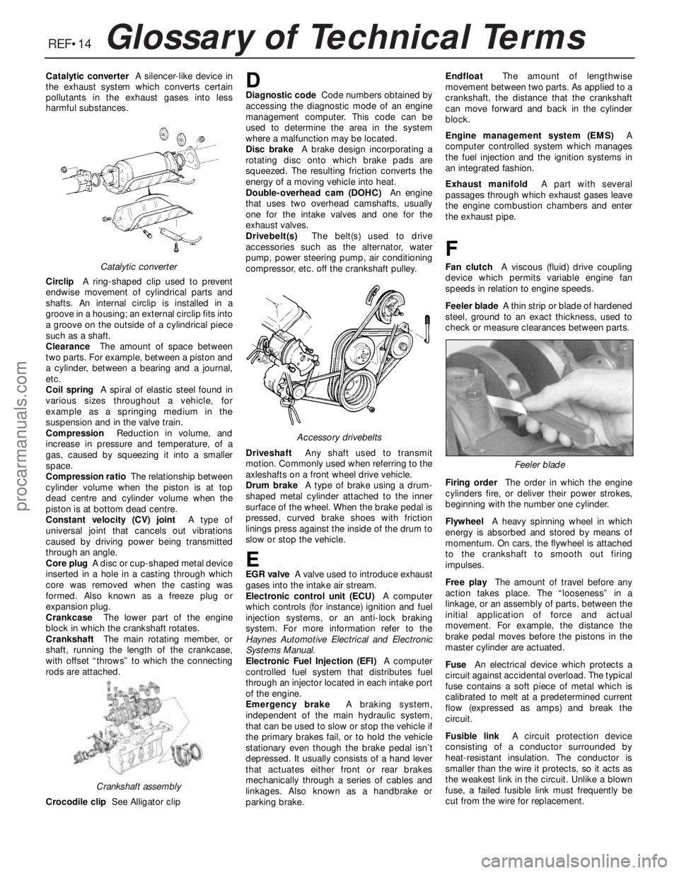
Feeler bladeA thin strip or blade of hardened
steel, ground to an exact thickness, used to
check or measure clearances between parts.
Firing orderThe order in which the engine
cylinders fire, or deliver their power strokes,
beginning with the number one cylinder.
Flywheel A heavy spinning wheel in which
energy is absorbed and stored by means of
momentum. On cars, the flywheel is attached
to the crankshaft to smooth out firing
impulses.
Free playThe amount of travel before any
action takes place. The “looseness” in a
linkage, or an assembly of parts, between the
initial application of force and actual
movement. For example, the distance the
brake pedal moves before the pistons in the
master cylinder are actuated.
FuseAn electrical device which protects a
circuit against accidental overload. The typical
fuse contains a soft piece of metal which is
calibrated to melt at a predetermined current
flow (expressed as amps) and break the
circuit.
Fusible linkA circuit protection device
consisting of a conductor surrounded by
heat-resistant insulation. The conductor is
smaller than the wire it protects, so it acts as
the weakest link in the circuit. Unlike a blown
fuse, a failed fusible link must frequently be
cut from the wire for replacement.Catalytic converter
Crankshaft assembly
Accessory drivebelts
Feeler blade
procarmanuals.com