1993 FORD MONDEO brake sensor
[x] Cancel search: brake sensorPage 18 of 279
1•4
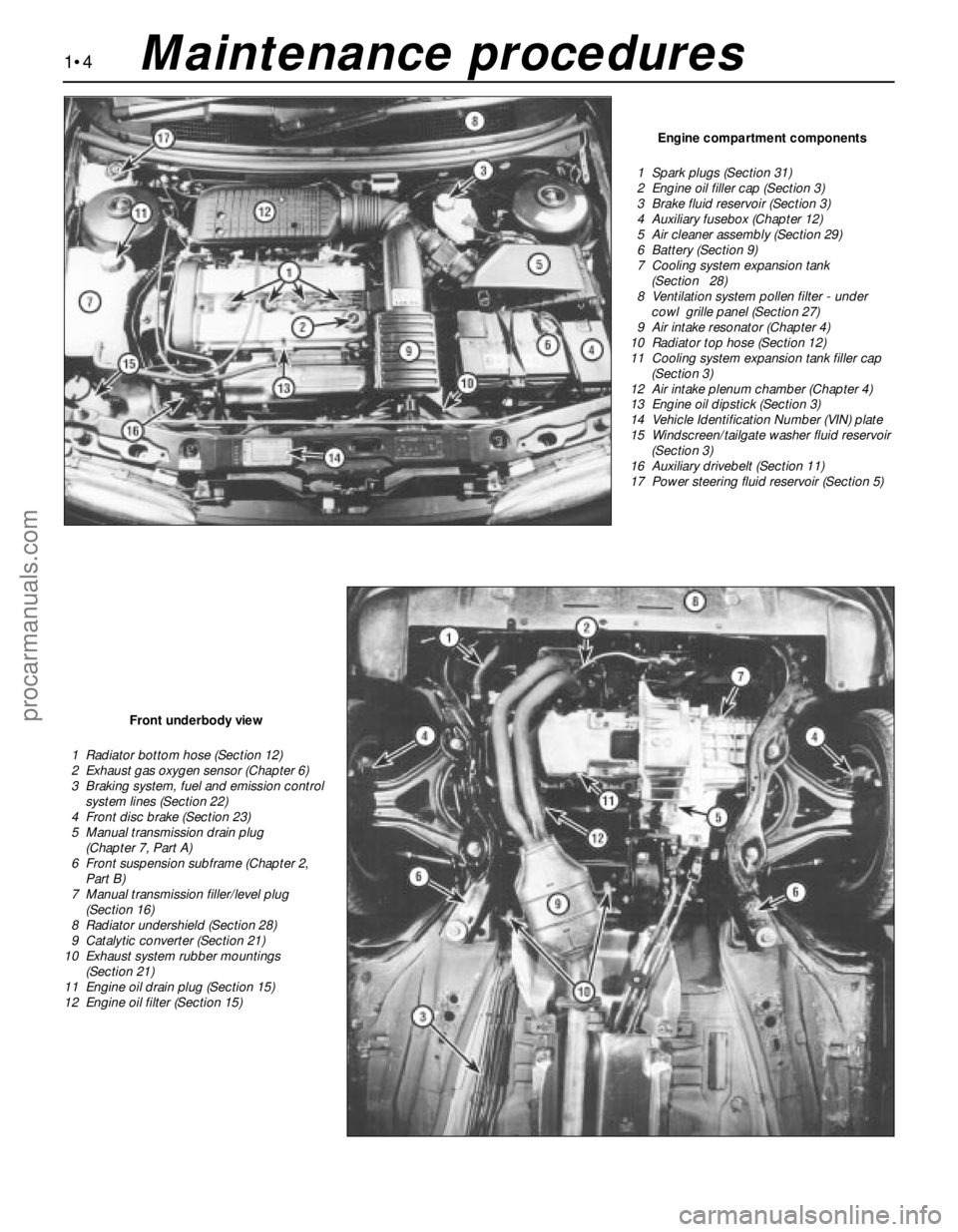
Engine compartment components
1 Spark plugs (Section 31)
2 Engine oil filler cap (Section 3)
3 Brake fluid reservoir (Section 3)
4 Auxiliary fusebox (Chapter 12)
5 Air cleaner assembly (Section 29)
6 Battery (Section 9)
7 Cooling system expansion tank
(Section 28)
8 Ventilation system pollen filter - under
cowl grille panel (Section 27)
9 Air intake resonator (Chapter 4)
10 Radiator top hose (Section 12)
11 Cooling system expansion tank filler cap
(Section 3)
12 Air intake plenum chamber (Chapter 4)
13 Engine oil dipstick (Section 3)
14 Vehicle Identification Number (VIN) plate
15 Windscreen/tailgate washer fluid reservoir
(Section 3)
16 Auxiliary drivebelt (Section 11)
17 Power steering fluid reservoir (Section 5)
Front underbody view
1 Radiator bottom hose (Section 12)
2 Exhaust gas oxygen sensor (Chapter 6)
3 Braking system, fuel and emission control
system lines (Section 22)
4 Front disc brake (Section 23)
5 Manual transmission drain plug
(Chapter 7, Part A)
6 Front suspension subframe (Chapter 2,
Part B)
7 Manual transmission filler/level plug
(Section 16)
8 Radiator undershield (Section 28)
9 Catalytic converter (Section 21)
10 Exhaust system rubber mountings
(Section 21)
11 Engine oil drain plug (Section 15)
12 Engine oil filter (Section 15)
Maintenance procedures
procarmanuals.com
Page 47 of 279
throttle linkage as described in Chapter 4.
Where fitted, disconnect also the cruise
control actuator cable (see Chapter 12).
3Remove the timing belt upper cover (see
Section 9).
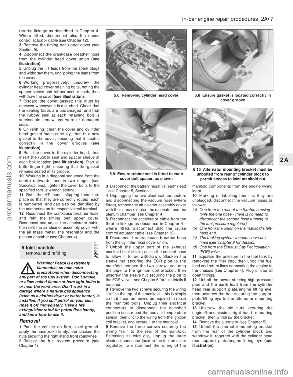
4Disconnect the crankcase breather hose
from the cylinder head cover union (see
illustration).
5Unplug the HT leads from the spark plugs
and withdraw them, unclipping the leads from
the cover.
6Working progressively, unscrew the
cylinder head cover retaining bolts, noting the
spacer sleeve and rubber seal at each, then
withdraw the cover (see illustration).
7Discard the cover gasket; this mustbe
renewed whenever it is disturbed. Check that
the sealing faces are undamaged, and that
the rubber seal at each retaining bolt is
serviceable; renew any worn or damaged
seals.
8On refitting, clean the cover and cylinder
head gasket faces carefully, then fit a new
gasket to the cover, ensuring that it locates
correctly in the cover grooves (see
illustration).
9Refit the cover to the cylinder head, then
insert the rubber seal and spacer sleeve at
each bolt location (see illustration). Start all
bolts finger-tight, ensuring that the gasket
remains seated in its groove.
10Working in a diagonal sequence from the
centre outwards, and in two stages (see
Specifications), tighten the cover bolts to the
specified torque wrench setting.
11Refit the HT leads, clipping them into
place so that they are correctly routed; each
is numbered, and can also be identified by
the numbering on its respective coil terminal.
12Reconnect the crankcase breather hose,
and refit the timing belt upper cover.
Reconnect and adjust the accelerator cable,
then refit the air cleaner assembly cover with
the air mass meter, the resonator and the
plenum chamber (see Chapter 4).
Warning: Petrol is extremely
flammable, so take extra
precautions when disconnecting
any part of the fuel system. Don’t smoke,
or allow naked flames or bare light bulbs in
or near the work area. Don’t work in a
garage where a natural gas appliance
(such as a clothes dryer or water heater) is
installed. If you spill petrol on your skin,
rinse it off immediately. Have a fire
extinguisher rated for petrol fires handy,
and know how to use it.
Removal
1Park the vehicle on firm, level ground,
apply the handbrake firmly, and slacken the
nuts securing the right-hand front roadwheel.
2Relieve the fuel system pressure (see
Chapter 4).3Disconnect the battery negative (earth) lead
- see Chapter 5, Section 1.
4Unplugging the two electrical connectors
and disconnecting the vacuum hose (where
fitted), remove the air cleaner assembly cover
with the air mass meter, the resonator and the
plenum chamber (see Chapter 4).
5Disconnect the accelerator cable from the
throttle linkage as described in Chapter 4 -
where fitted, disconnect also the cruise
control actuator cable (see Chapter 12).
6Disconnect the crankcase breather hose
from the cylinder head cover union.
7Unbolt the upper part of the exhaust
manifold heat shield; unclip the coolant hose
to allow it to be withdrawn. Slacken the
sleeve nut securing the EGR pipe to the
manifold, remove the two screws securing
the pipe to the ignition coil bracket, then
unscrew the sleeve nut securing the pipe to
the EGR valve - see Chapter 6 for full details if
required.
8Remove the two screws securing the wiring
“rail” to the top of the manifold - this is simply
so that it can be moved as required to reach
the manifold bolts. Unplug their electrical
connectors to disconnect the camshaft
position sensor and the coolant temperature
sensor, then unclip the wiring from the ignition
coil bracket, and secure it to the manifold.
9Remove the three screws securing the
wiring “rail” to the rear of the manifold.
Releasing its wire clip, unplug the large
electrical connector (next to the fuel pressure
regulator) to disconnect the wiring of themanifold components from the engine wiring
loom.
10Marking or labelling them as they are
unplugged, disconnect the vacuum hoses as
follows:
(a) One from the rear of the throttle housing
(only the one hose - there is no need to
disconnect the second hose running to
the fuel pressure regulator).
(b) One from the union on the manifold’s left-
hand end.
(c) The braking system vacuum servo unit
hose (see Chapter 9 for details).
(d) One from the Exhaust Gas Recirculation
(EGR) valve.
11Equalise the pressure in the fuel tank by
removing the filler cap, then undo the fuel
feed and return lines connecting the engine to
the chassis (see Chapter 4). Plug or cap all
open fittings.
12Unbolt the power steering high-pressure
pipe and the earth lead from the cylinder
head rear support plate/engine lifting eye,
then unscrew the bolt securing the support
plate/lifting eye to the alternator mounting
bracket.
13Unscrew the six nuts securing the
engine/transmission right-hand mounting
bracket, then withdraw the bracket.
14Remove the alternator (see Chapter 5).
15Unbolt the alternator mounting bracket
from the rear of the cylinder block and
withdraw it, together with the cylinder head
rear support plate/engine lifting eye (see
illustration).
6 Inlet manifold -
removal and refitting
In-car engine repair procedures 2A•7
2A
5.8 Ensure gasket is located correctly in
cover groove5.6 Removing cylinder head cover
5.9 Ensure rubber seal is fitted to each
cover bolt spacer, as shown6.15 Alternator mounting bracket must be
unbolted from rear of cylinder block to
permit access to inlet manifold nut
procarmanuals.com
Page 71 of 279
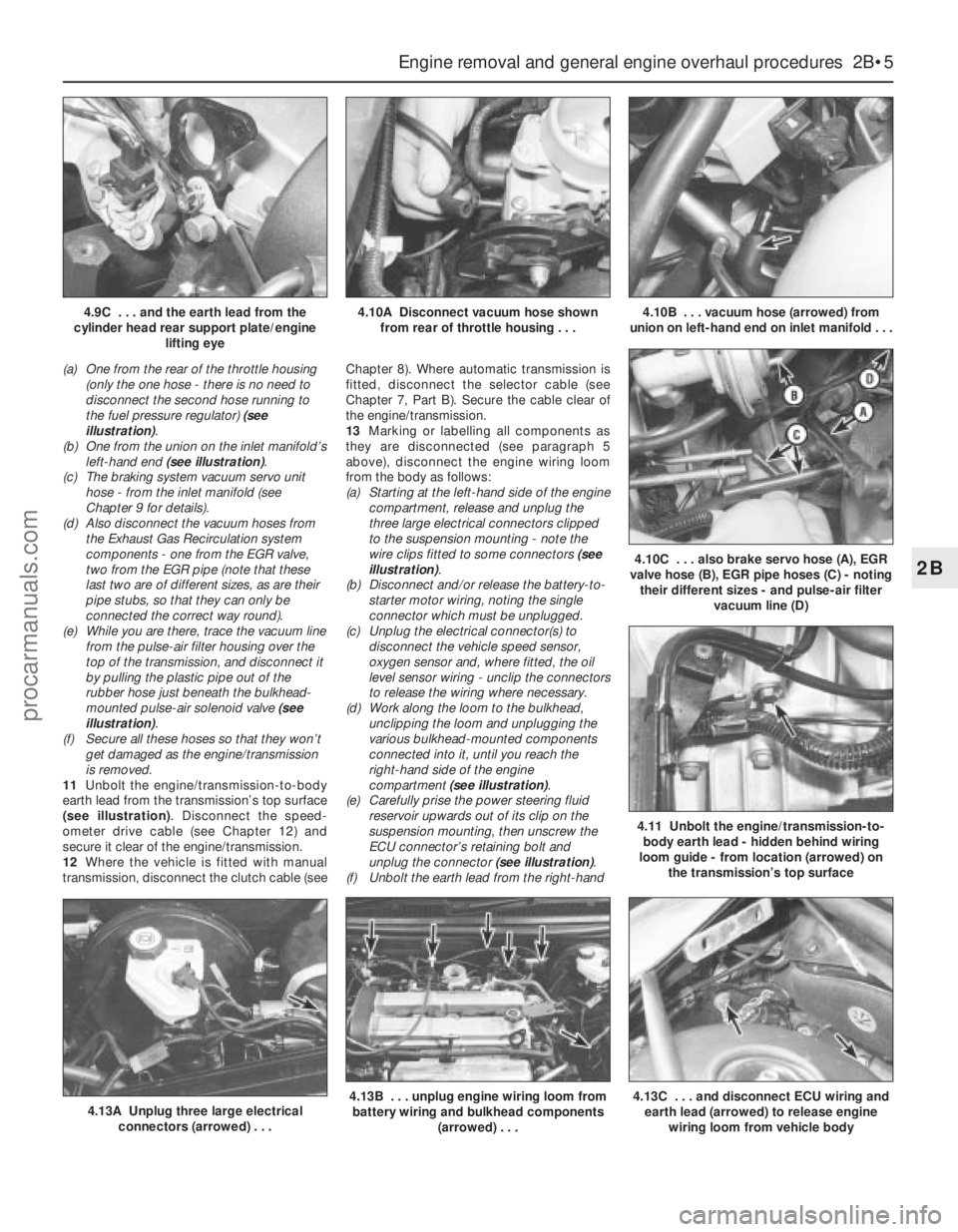
(a) One from the rear of the throttle housing
(only the one hose - there is no need to
disconnect the second hose running to
the fuel pressure regulator) (see
illustration).
(b) One from the union on the inlet manifold’s
left-hand end (see illustration).
(c) The braking system vacuum servo unit
hose - from the inlet manifold (see
Chapter 9 for details).
(d) Also disconnect the vacuum hoses from
the Exhaust Gas Recirculation system
components - one from the EGR valve,
two from the EGR pipe (note that these
last two are of different sizes, as are their
pipe stubs, so that they can only be
connected the correct way round).
(e) While you are there, trace the vacuum line
from the pulse-air filter housing over the
top of the transmission, and disconnect it
by pulling the plastic pipe out of the
rubber hose just beneath the bulkhead-
mounted pulse-air solenoid valve (see
illustration).
(f) Secure all these hoses so that they won’t
get damaged as the engine/transmission
is removed.
11Unbolt the engine/transmission-to-body
earth lead from the transmission’s top surface
(see illustration). Disconnect the speed-
ometer drive cable (see Chapter 12) and
secure it clear of the engine/transmission.
12Where the vehicle is fitted with manual
transmission, disconnect the clutch cable (seeChapter 8). Where automatic transmission is
fitted, disconnect the selector cable (see
Chapter 7, Part B). Secure the cable clear of
the engine/transmission.
13Marking or labelling all components as
they are disconnected (see paragraph 5
above), disconnect the engine wiring loom
from the body as follows:
(a) Starting at the left-hand side of the engine
compartment, release and unplug the
three large electrical connectors clipped
to the suspension mounting - note the
wire clips fitted to some connectors (see
illustration).
(b) Disconnect and/or release the battery-to-
starter motor wiring, noting the single
connector which must be unplugged.
(c) Unplug the electrical connector(s) to
disconnect the vehicle speed sensor,
oxygen sensor and, where fitted, the oil
level sensor wiring - unclip the connectors
to release the wiring where necessary.
(d) Work along the loom to the bulkhead,
unclipping the loom and unplugging the
various bulkhead-mounted components
connected into it, until you reach the
right-hand side of the engine
compartment (see illustration).
(e) Carefully prise the power steering fluid
reservoir upwards out of its clip on the
suspension mounting, then unscrew the
ECU connector’s retaining bolt and
unplug the connector (see illustration).
(f) Unbolt the earth lead from the right-hand
Engine removal and general engine overhaul procedures 2B•5
2B
4.13A Unplug three large electrical
connectors (arrowed) . . .4.13B . . . unplug engine wiring loom from
battery wiring and bulkhead components
(arrowed) . . .4.13C . . . and disconnect ECU wiring and
earth lead (arrowed) to release engine
wiring loom from vehicle body
4.9C . . . and the earth lead from the
cylinder head rear support plate/engine
lifting eye4.10A Disconnect vacuum hose shown
from rear of throttle housing . . .4.10B . . . vacuum hose (arrowed) from
union on left-hand end on inlet manifold . . .
4.10C . . . also brake servo hose (A), EGR
valve hose (B), EGR pipe hoses (C) - noting
their different sizes - and pulse-air filter
vacuum line (D)
4.11 Unbolt the engine/transmission-to-
body earth lead - hidden behind wiring
loom guide - from location (arrowed) on
the transmission’s top surface
procarmanuals.com
Page 99 of 279
Chapter 4 Fuel and exhaust systems
Accelerator cable (models with traction control) -
removal, refitting and adjustment . . . . . . . . . . . . . . . . . . . . . . . . . 6
Accelerator cable (models without traction control) -
removal, refitting and adjustment . . . . . . . . . . . . . . . . . . . . . . . . . 5
Accelerator pedal - removal and refitting . . . . . . . . . . . . . . . . . . . . . 7
Air cleaner assembly/air intake components - removal and refitting . 4
Air filter element renewal . . . . . . . . . . . . . . . . . . . . . . . See Chapter 1
Catalytic converter . . . . . . . . . . . . . . . . . . . . . . . . . . . . See Chapter 6
Exhaust manifold - removal and refitting . . . . . . . . . . . See Chapter 2A
Exhaust system - general information and component renewal . . . . 17
Exhaust system check . . . . . . . . . . . . . . . . . . . . . . . . . See Chapter 1
Fuel cut-off switch - removal and refitting . . . . . . . . . . . . . . . . . . . . 13
Fuel filter renewal . . . . . . . . . . . . . . . . . . . . . . . . . . . . . See Chapter 1
Fuel injection system/engine management system - check . . . . . . . 15
Fuel injection system/engine management system - general . . . . . 14Fuel lines and fittings - general information . . . . . . . . . . . . . . . . . . . 3
Fuel pump/fuel gauge sender unit - removal and refitting . . . . . . . . 9
Fuel pump/fuel pressure - check . . . . . . . . . . . . . . . . . . . . . . . . . . . 8
Fuel system - depressurisation . . . . . . . . . . . . . . . . . . . . . . . . . . . . . 2
Fuel system components - check and renewal . . . . . . . . . . . . . . . . 16
Fuel tank - removal and refitting . . . . . . . . . . . . . . . . . . . . . . . . . . . . 10
Fuel tank cleaning and repair - general information . . . . . . . . . . . . . 11
General information and precautions . . . . . . . . . . . . . . . . . . . . . . . . 1
Idle speed and mixture check and adjustment . . . . . . See Section 14
Inlet manifold - removal and refitting . . . . . . . . . . . . . . See Chapter 2A
Oxygen sensor . . . . . . . . . . . . . . . . . . . . . . . . . . . . . . . See Chapter 6
Roll-over valves - removal and refitting . . . . . . . . . . . . . . . . . . . . . . . 12
Underbody fuel/brake line check . . . . . . . . . . . . . . . . . See Chapter 1
Underbonnet hose check . . . . . . . . . . . . . . . . . . . . . . . See Chapter 1
General
Idle speed:
Regulated - nominal (± 50 rpm) . . . . . . . . . . . . . . . . . . . . . . . . . . . . . . 830 to 880 rpm*
Unregulated - base . . . . . . . . . . . . . . . . . . . . . . . . . . . . . . . . . . . . . . . 1500 rpm*
Idle mixture (CO level) . . . . . . . . . . . . . . . . . . . . . . . . . . . . . . . . . . . . . . . Not available
* Given for reference only - not adjustable.
Rev limiter operation
Fuel injectors shut off at:
Automatic transmission, position “N” selected . . . . . . . . . . . . . . . . . . 4100 rpm
Automatic transmission, any other position selected . . . . . . . . . . . . . 6800 rpm (approximately)
Manual transmission . . . . . . . . . . . . . . . . . . . . . . . . . . . . . . . . . . . . . . 6800 to 7100 rpm
Fuel pressure
Regulated fuel pressure - engine running at idle speed:
Pressure regulator vacuum hose connected . . . . . . . . . . . . . . . . . . . 2.1 ± 0.2 bars
Pressure regulator vacuum hose disconnected . . . . . . . . . . . . . . . . . 2.7 ± 0.2 bars
Note:When the ignition is switched off, the system should hold 1.8 bars for 5 minutes. If the engine is hot, the pressure may rise to maximum of
2.7 bars during this check. Pressure regulator (when reconnected) should prevent any higher pressure being reached.
Fuel injectors
Resistance . . . . . . . . . . . . . . . . . . . . . . . . . . . . . . . . . . . . . . . . . . . . . . . . 13.7 to 15.2 ohms
Idle speed control valve
Resistance . . . . . . . . . . . . . . . . . . . . . . . . . . . . . . . . . . . . . . . . . . . . . . . . 6 to 14 ohms
Idle-increase solenoid valve
Resistance . . . . . . . . . . . . . . . . . . . . . . . . . . . . . . . . . . . . . . . . . . . . . . . . 50 to 120 ohms
Torque wrench settingsNm lbf ft
Plenum chamber-to-inlet manifold fasteners . . . . . . . . . . . . . . . . . . . . . 4 3
Throttle housing-to-inlet manifold screws . . . . . . . . . . . . . . . . . . . . . . . 10 7
Idle speed control valve bolts . . . . . . . . . . . . . . . . . . . . . . . . . . . . . . . . . 6 4
Fuel pressure regulator bolts . . . . . . . . . . . . . . . . . . . . . . . . . . . . . . . . . 6 4
Fuel injector bolts . . . . . . . . . . . . . . . . . . . . . . . . . . . . . . . . . . . . . . . . . . 6 4
Fuel rail-to-inlet manifold bolts . . . . . . . . . . . . . . . . . . . . . . . . . . . . . . . . 10 7
Fuel feed and return line threaded couplings at fuel rail . . . . . . . . . . . . . 24 to 30 17 to 22
All exhaust system nuts and bolts . . . . . . . . . . . . . . . . . . . . . . . . . . . . . 40 to 45 30 to 33
4•1
Easy,suitable for
novice with little
experienceFairly easy,suitable
for beginner with
some experienceFairly difficult,suitable
for competent DIY
mechanicDifficult,suitable for
experienced DIY
mechanicVery difficult,
suitable for expert DIY
or professional
Degrees of difficulty
Specifications Contents
4
procarmanuals.com
Page 119 of 279
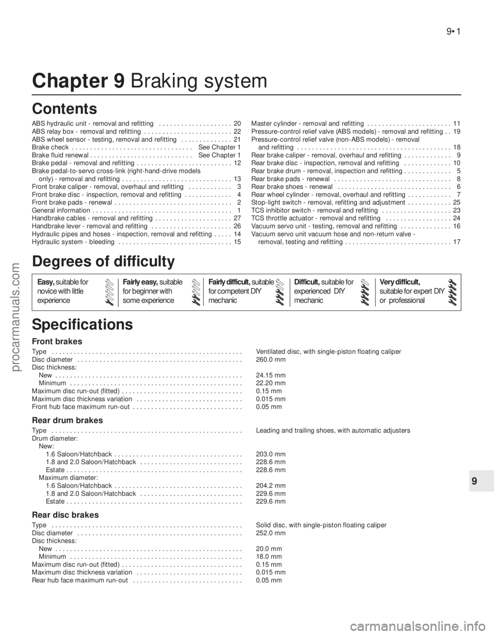
Chapter 9 Braking system
ABS hydraulic unit - removal and refitting . . . . . . . . . . . . . . . . . . . . 20
ABS relay box - removal and refitting . . . . . . . . . . . . . . . . . . . . . . . . 22
ABS wheel sensor - testing, removal and refitting . . . . . . . . . . . . . . 21
Brake check . . . . . . . . . . . . . . . . . . . . . . . . . . . . . . . . . See Chapter 1
Brake fluid renewal . . . . . . . . . . . . . . . . . . . . . . . . . . . . See Chapter 1
Brake pedal - removal and refitting . . . . . . . . . . . . . . . . . . . . . . . . . . 12
Brake pedal-to-servo cross-link (right-hand-drive models
only) - removal and refitting . . . . . . . . . . . . . . . . . . . . . . . . . . . . . . 13
Front brake caliper - removal, overhaul and refitting . . . . . . . . . . . . 3
Front brake disc - inspection, removal and refitting . . . . . . . . . . . . . 4
Front brake pads - renewal . . . . . . . . . . . . . . . . . . . . . . . . . . . . . . . . 2
General information . . . . . . . . . . . . . . . . . . . . . . . . . . . . . . . . . . . . . . 1
Handbrake cables - removal and refitting . . . . . . . . . . . . . . . . . . . . . 27
Handbrake lever - removal and refitting . . . . . . . . . . . . . . . . . . . . . . 26
Hydraulic pipes and hoses - inspection, removal and refitting . . . . . 14
Hydraulic system - bleeding . . . . . . . . . . . . . . . . . . . . . . . . . . . . . . . 15Master cylinder - removal and refitting . . . . . . . . . . . . . . . . . . . . . . . 11
Pressure-control relief valve (ABS models) - removal and refitting . . 19
Pressure-control relief valve (non-ABS models) - removal
and refitting . . . . . . . . . . . . . . . . . . . . . . . . . . . . . . . . . . . . . . . . . . 18
Rear brake caliper - removal, overhaul and refitting . . . . . . . . . . . . . 9
Rear brake disc - inspection, removal and refitting . . . . . . . . . . . . . 10
Rear brake drum - removal, inspection and refitting . . . . . . . . . . . . . 5
Rear brake pads - renewal . . . . . . . . . . . . . . . . . . . . . . . . . . . . . . . . 8
Rear brake shoes - renewal . . . . . . . . . . . . . . . . . . . . . . . . . . . . . . . 6
Rear wheel cylinder - removal, overhaul and refitting . . . . . . . . . . . . 7
Stop-light switch - removal, refitting and adjustment . . . . . . . . . . . . 25
TCS inhibitor switch - removal and refitting . . . . . . . . . . . . . . . . . . . 23
TCS throttle actuator - removal and refitting . . . . . . . . . . . . . . . . . . 24
Vacuum servo unit - testing, removal and refitting . . . . . . . . . . . . . . 16
Vacuum servo unit vacuum hose and non-return valve -
removal, testing and refitting . . . . . . . . . . . . . . . . . . . . . . . . . . . . . 17
Front brakes
Type . . . . . . . . . . . . . . . . . . . . . . . . . . . . . . . . . . . . . . . . . . . . . . . . . . . . Ventilated disc, with single-piston floating caliper
Disc diameter . . . . . . . . . . . . . . . . . . . . . . . . . . . . . . . . . . . . . . . . . . . . . 260.0 mm
Disc thickness:
New . . . . . . . . . . . . . . . . . . . . . . . . . . . . . . . . . . . . . . . . . . . . . . . . . . . 24.15 mm
Minimum . . . . . . . . . . . . . . . . . . . . . . . . . . . . . . . . . . . . . . . . . . . . . . . 22.20 mm
Maximum disc run-out (fitted) . . . . . . . . . . . . . . . . . . . . . . . . . . . . . . . . . 0.15 mm
Maximum disc thickness variation . . . . . . . . . . . . . . . . . . . . . . . . . . . . . 0.015 mm
Front hub face maximum run-out . . . . . . . . . . . . . . . . . . . . . . . . . . . . . . 0.05 mm
Rear drum brakes
Type . . . . . . . . . . . . . . . . . . . . . . . . . . . . . . . . . . . . . . . . . . . . . . . . . . . . Leading and trailing shoes, with automatic adjusters
Drum diameter:
New:
1.6 Saloon/Hatchback . . . . . . . . . . . . . . . . . . . . . . . . . . . . . . . . . . . 203.0 mm
1.8 and 2.0 Saloon/Hatchback . . . . . . . . . . . . . . . . . . . . . . . . . . . . 228.6 mm
Estate . . . . . . . . . . . . . . . . . . . . . . . . . . . . . . . . . . . . . . . . . . . . . . . . 228.6 mm
Maximum diameter:
1.6 Saloon/Hatchback . . . . . . . . . . . . . . . . . . . . . . . . . . . . . . . . . . . 204.2 mm
1.8 and 2.0 Saloon/Hatchback . . . . . . . . . . . . . . . . . . . . . . . . . . . . 229.6 mm
Estate . . . . . . . . . . . . . . . . . . . . . . . . . . . . . . . . . . . . . . . . . . . . . . . . 229.6 mm
Rear disc brakes
Type . . . . . . . . . . . . . . . . . . . . . . . . . . . . . . . . . . . . . . . . . . . . . . . . . . . . Solid disc, with single-piston floating caliper
Disc diameter . . . . . . . . . . . . . . . . . . . . . . . . . . . . . . . . . . . . . . . . . . . . . 252.0 mm
Disc thickness:
New . . . . . . . . . . . . . . . . . . . . . . . . . . . . . . . . . . . . . . . . . . . . . . . . . . . 20.0 mm
Minimum . . . . . . . . . . . . . . . . . . . . . . . . . . . . . . . . . . . . . . . . . . . . . . . 18.0 mm
Maximum disc run-out (fitted) . . . . . . . . . . . . . . . . . . . . . . . . . . . . . . . . . 0.15 mm
Maximum disc thickness variation . . . . . . . . . . . . . . . . . . . . . . . . . . . . . 0.015 mm
Rear hub face maximum run-out . . . . . . . . . . . . . . . . . . . . . . . . . . . . . . 0.05 mm
9•1
Easy,suitable for
novice with little
experienceFairly easy,suitable
for beginner with
some experienceFairly difficult,suitable
for competent DIY
mechanicDifficult,suitable for
experienced DIY
mechanicVery difficult,
suitable for expert DIY
or professional
Degrees of difficulty
Specifications Contents
9
procarmanuals.com
Page 121 of 279
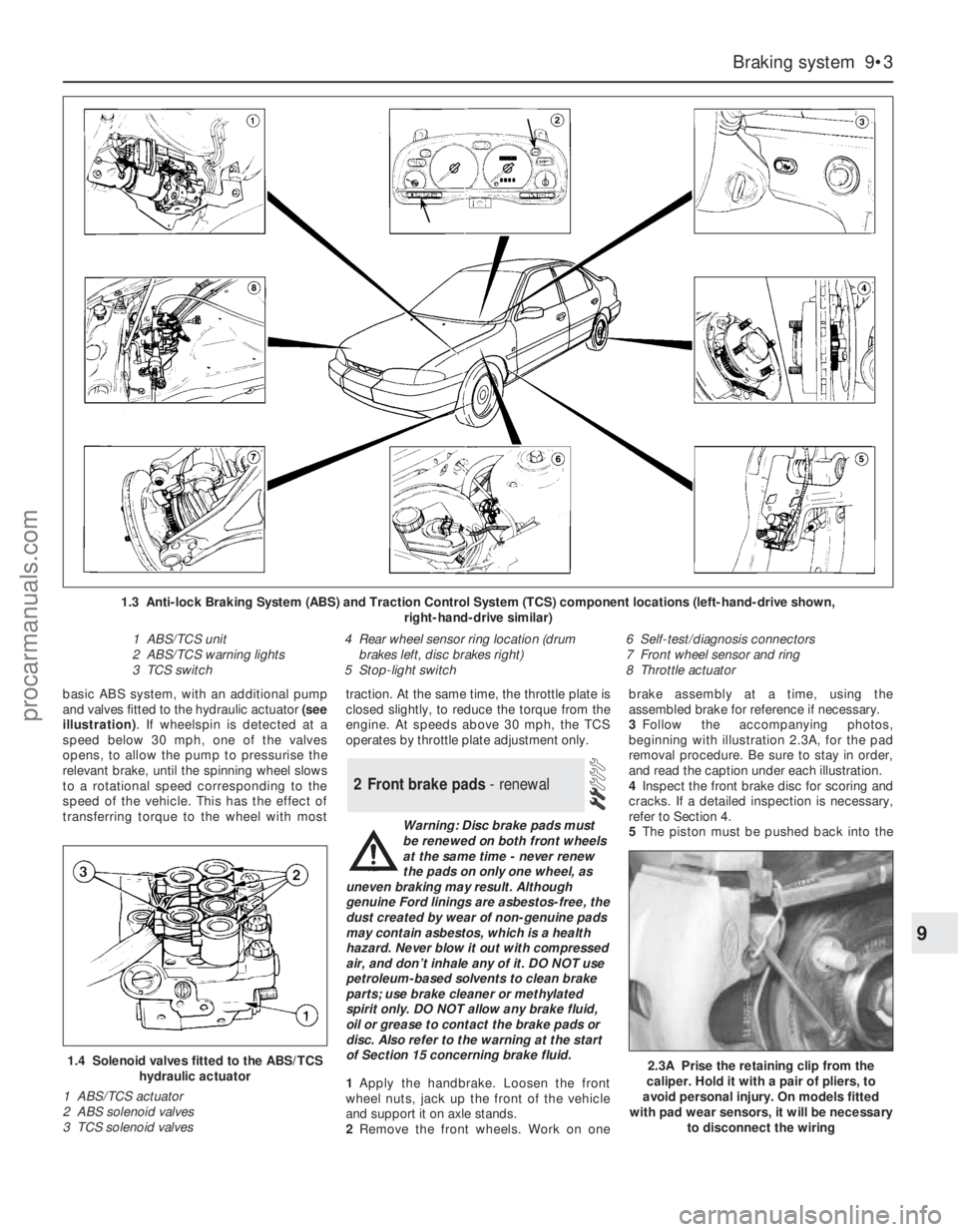
basic ABS system, with an additional pump
and valves fitted to the hydraulic actuator (see
illustration). If wheelspin is detected at a
speed below 30 mph, one of the valves
opens, to allow the pump to pressurise the
relevant brake, until the spinning wheel slows
to a rotational speed corresponding to the
speed of the vehicle. This has the effect of
transferring torque to the wheel with mosttraction. At the same time, the throttle plate is
closed slightly, to reduce the torque from the
engine. At speeds above 30 mph, the TCS
operates by throttle plate adjustment only.
Warning: Disc brake pads must
be renewed on both front wheels
at the same time - never renew
the pads on only one wheel, as
uneven braking may result. Although
genuine Ford linings are asbestos-free, the
dust created by wear of non-genuine pads
may contain asbestos, which is a health
hazard. Never blow it out with compressed
air, and don’t inhale any of it. DO NOT use
petroleum-based solvents to clean brake
parts; use brake cleaner or methylated
spirit only. DO NOT allow any brake fluid,
oil or grease to contact the brake pads or
disc. Also refer to the warning at the start
of Section 15 concerning brake fluid.
1Apply the handbrake. Loosen the front
wheel nuts, jack up the front of the vehicle
and support it on axle stands.
2Remove the front wheels. Work on onebrake assembly at a time, using the
assembled brake for reference if necessary.
3Follow the accompanying photos,
beginning with illustration 2.3A, for the pad
removal procedure. Be sure to stay in order,
and read the caption under each illustration.
4Inspect the front brake disc for scoring and
cracks. If a detailed inspection is necessary,
refer to Section 4.
5The piston must be pushed back into the
2 Front brake pads - renewal
Braking system 9•3
9
1.4 Solenoid valves fitted to the ABS/TCS
hydraulic actuator
1 ABS/TCS actuator
2 ABS solenoid valves
3 TCS solenoid valves
1.3 Anti-lock Braking System (ABS) and Traction Control System (TCS) component locations (left-hand-drive shown,
right-hand-drive similar)
1 ABS/TCS unit
2 ABS/TCS warning lights
3 TCS switch4 Rear wheel sensor ring location (drum
brakes left, disc brakes right)
5 Stop-light switch6 Self-test/diagnosis connectors
7 Front wheel sensor and ring
8 Throttle actuator
2.3A Prise the retaining clip from the
caliper. Hold it with a pair of pliers, to
avoid personal injury. On models fitted
with pad wear sensors, it will be necessary
to disconnect the wiring
procarmanuals.com
Page 132 of 279
Note:If any part of the ABS hydraulic unit is
defective, it must be renewed as an assembly.
Apart from the relay box (Section 22),
individual spare parts are not available.
Removal
1Remove both pressure-control relief valves
as described in Section 19.
2Identify the location of the remaining brake
hydraulic pipes on the ABS hydraulic unit,
then unscrew the union nuts and pull out the
pipes. Carefully bend the pipes away from the
hydraulic unit, to allow the unit to be removed.
3Disconnect the multi-plugs from the
hydraulic unit. To disconnect the main 22-pin
multi-plug, push the locktab, then swivel the
multi-plug outwards and unhook it.
Right-hand drive models
4Have an assistant hold the brake pedal
depressed, then extract the spring clip and
remove the clevis pin securing the servo unit
pushrod to the pedal cross-link arm.
5Remove the vacuum servo unit from the
engine compartment.
Left-hand drive models
6Unscrew the nut securing the pedal
trunnion to the servo unit pushrod inside the
passenger compartment. The nut is located
near the top of the pedal, and is accessible
through an access hole. For improved access,
remove the lower facia panel first.
7Remove the vacuum servo unit, together
with the pushrod, from the engine
compartment. Take care not to damage the
rubber grommet in the bulkhead.
All models
8Unscrew the pump mounting nut.
9Raise the left-hand side of the ABS
hydraulic unit, then swivel the unit out of the
right-hand mounting. Take care not to lose the
bracket studs and insulator ring.
Refitting
10Locate the insulator ring on the pump
end, and fit the stud cap to the insulator ring.
11Lower the ABS hydraulic unit into
position, right-hand end first.
12Fit the right-hand bracket studs onto the
insulators.
13Lower the left-hand end of the ABS
hydraulic unit onto the bracket, then fit and
tighten the pump mounting nut.
Left-hand drive models
14Locate the vacuum servo unit and
pushrod on the bulkhead bracket, taking care
not to damage the rubber grommet.
15Insert the pushrod in the pedal trunnion,
and tighten the nut.
16Refit the lower facia panel if it was
removed.
Right-hand drive models
17Locate the vacuum servo unit and
pushrod on the bulkhead bracket.
18Refit the clevis pin and spring clip
securing the servo unit pushrod to the pedal
cross-link arm.
All models
19Reconnect the multi-plugs to the
hydraulic unit.
20Reconnect the brake pipes to the
hydraulic unit, and tighten the union nuts.
21Refit both pressure-control relief valves,
with reference to Section 20.
Testing
1Checking of the sensors is done before
removal, connecting a voltmeter to the
disconnected sensor multi-plug. Using an
analogue (moving coil) meter is not practical,
since the meter does not respond quickly
enough. A digital meter having an AC facility
may be used to check that the sensor is
operating correctly. To do this, raise the
relevant wheel then disconnect the wiring to
the ABS sensor and connect the meter to it.
Spin the wheel and check that the output
voltage is between 1.5 and 2.0 volts,
depending on how fast the wheel is spun.
Alternatively, an oscilloscope may be used to
check the output of the sensor - an alternating
current will be traced on the screen, of
magnitude depending on the speed of the
rotating wheel.
2If the sensor output is low or zero, renew
the sensor.
Removal
Front wheel sensor
3Apply the handbrake, jack up the front of
the vehicle and support it on axle stands.
Remove the relevant wheel.
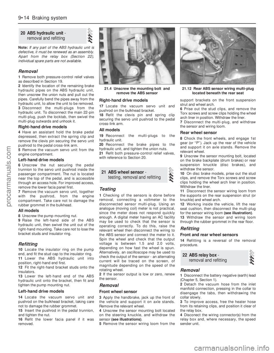
4Unscrew the sensor mounting bolt located
on the steering knuckle, and withdraw the
sensor (see illustrations).
5Remove the sensor wiring loom from thesupport brackets on the front suspension
strut and wheel arch.
6Prise out the stud clips, and remove the
Torx screws and screw clips holding the wheel
arch liner in position. Withdraw the liner.
7Disconnect the multi-plug, and withdraw
the sensor and wiring loom.
Rear wheel sensor
8Chock the front wheels, and engage 1st
gear (or “P”). Jack up the rear of the vehicle
and support it on axle stands. Remove the
relevant wheel.
9Unscrew the sensor mounting bolt, located
on the brake backplate (drum brakes) or rear
suspension knuckle (disc brakes), and
withdraw the sensor.
10On disc brake models, prise out the stud
clips, and remove the Torx screws and screw
clips holding the wheel arch liner in position.
Withdraw the liner.
11Disconnect the sensor wiring loom from
the supports on the rear suspension strut (or
knuckle) and wheel arch.
12Working inside the vehicle, lift the rear
seat cushion, then disconnect the multi-plug
for the sensor wiring loom (see illustration).
13Withdraw the sensor and wiring loom
through the rubber grommet in the rear floor.
Refitting
Front and rear wheel sensors
14Refitting is a reversal of the removal
procedure.
Removal
1Disconnect the battery negative (earth) lead
(Chapter 5, Section 1).
2Detach the vacuum hose from the inlet
manifold connection, pressing in the collar to
disengage the tabs, then withdrawing the
collar slowly.
3To improve access, free the heater hose
from its retaining clips, and position it clear of
the relay box.
4Disconect the wiring connector(s) from the
relay box and, where necessary, the speed
sender unit.
22 ABS relay box -
removal and refitting
21 ABS wheel sensor -
testing, removal and refitting
20 ABS hydraulic unit -
removal and refitting
9•14 Braking system
21.4 Unscrew the mounting bolt and
remove the ABS sensor21.12 Rear ABS sensor wiring multi-plug
located beneath the rear seat
procarmanuals.com
Page 141 of 279
24Ford specify the use of their STAR (Self-
Test Automatic Readout) tester; most Ford
dealers should have such equipment, and the
staff trained to use it effectively. The only
alternatives are as follows:
(a) To obtain one of those proprietary readers
which can interpret EEC-IV three-digit
codes - at present, such readers are too
expensive for the DIY enthusiast, but are
becoming more popular with smaller
specialist garages.
(b) To use an analogue voltmeter, whereby
the stored codes are displayed as sweeps
of the voltmeter needle. This option limits
the operator to a read-out of any codes
stored - ie, there is no control of sensors
and/or actuators - but can still be useful in
pinpointing the faulty part of the engine
management system. The display is
interpreted as follows. Each code
(whether fault code or
command/separator) is marked by a
three-to-four second pause - code “538”
would therefore be shown as long (3 to
4 seconds) pause, five fast sweeps of the
needle, slight (1 second) pause, three fast
sweeps, slight pause, eight fast sweeps,
long pause.
(c) Owners without access to such
equipment must take the vehicle to a Ford
dealer, or to an expert who has similar
equipment and the skill to use it.
25Because of the variations in the design of
fault code readers, it is not possible to give
exact details of the sequence of tests; the
manufacturer’s instructions must be followed,
in conjunction with the codes given below.
The following ten paragraphs outline the
procedure to be followed using a version of
the Ford STAR tester, to illustrate the general
principles, as well as notes to guide the owner
using only a voltmeter.
26The vehicle must be prepared by applying
the handbrake, switching off the air
conditioning (where fitted) and any other
electrical loads (lights, heated rear window,
etc), then selecting neutral (manual
transmission) or the “P” position (automatic
transmission). Where the engine is required to
be running, it must be fully warmed-up to
normal operating temperature before the test
is started. Using any adaptors required,
connect the fault code reader to the system
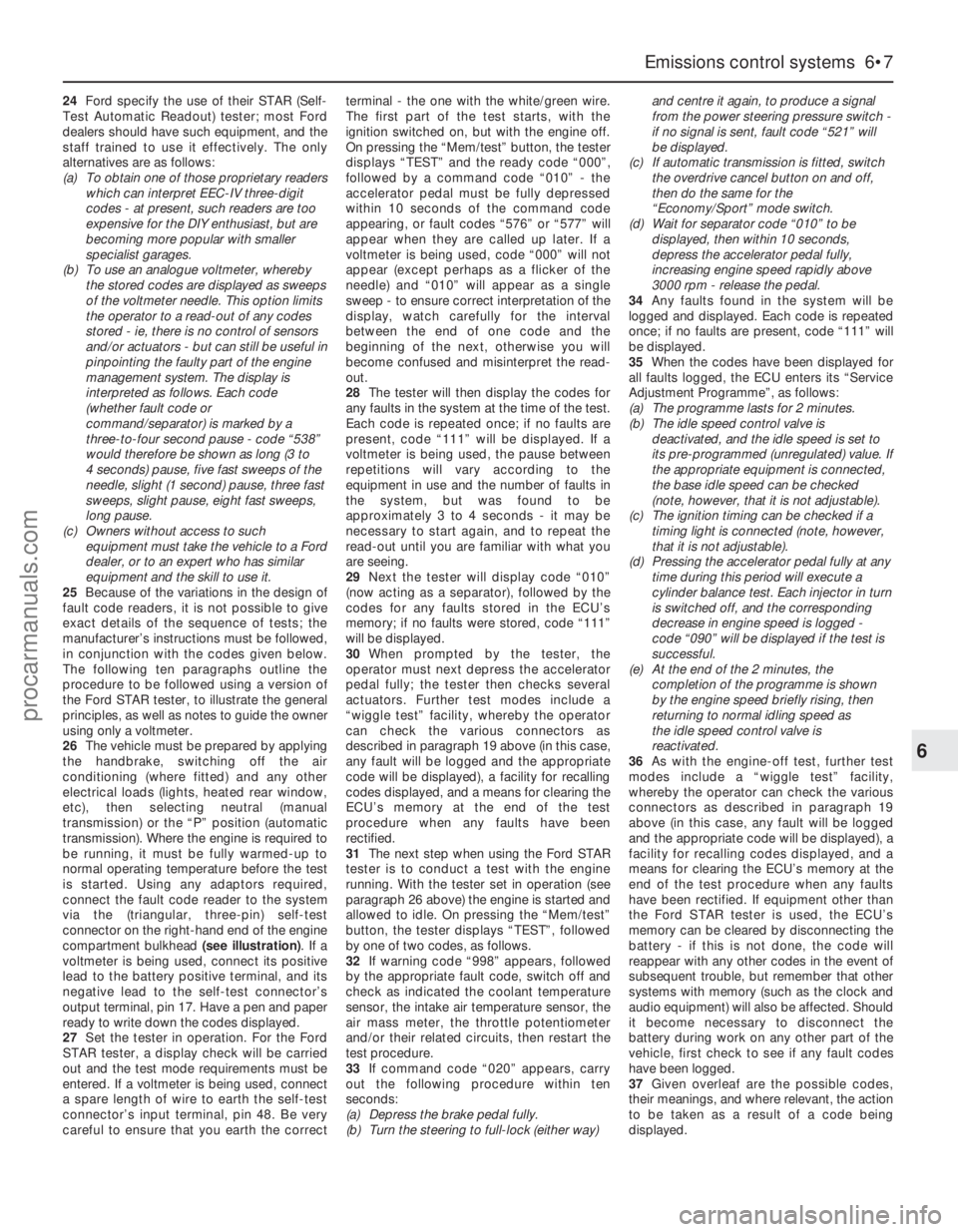
via the (triangular, three-pin) self-test
connector on the right-hand end of the engine
compartment bulkhead (see illustration). If a
voltmeter is being used, connect its positive
lead to the battery positive terminal, and its
negative lead to the self-test connector’s
output terminal, pin 17. Have a pen and paper
ready to write down the codes displayed.
27Set the tester in operation. For the Ford
STAR tester, a display check will be carried
out and the test mode requirements must be
entered. If a voltmeter is being used, connect
a spare length of wire to earth the self-test
connector’s input terminal, pin 48. Be very
careful to ensure that you earth the correctterminal - the one with the white/green wire.
The first part of the test starts, with the
ignition switched on, but with the engine off.
On pressing the “Mem/test” button, the tester
displays “TEST” and the ready code “000”,
followed by a command code “010” - the
accelerator pedal must be fully depressed
within 10 seconds of the command code
appearing, or fault codes “576” or “577” will
appear when they are called up later. If a
voltmeter is being used, code “000” will not
appear (except perhaps as a flicker of the
needle) and “010” will appear as a single
sweep - to ensure correct interpretation of the
display, watch carefully for the interval
between the end of one code and the
beginning of the next, otherwise you will
become confused and misinterpret the read-
out.
28The tester will then display the codes for
any faults in the system at the time of the test.
Each code is repeated once; if no faults are
present, code “111” will be displayed. If a
voltmeter is being used, the pause between
repetitions will vary according to the
equipment in use and the number of faults in
the system, but was found to be
approximately 3 to 4 seconds - it may be
necessary to start again, and to repeat the
read-out until you are familiar with what you
are seeing.
29Next the tester will display code “010”
(now acting as a separator), followed by the
codes for any faults stored in the ECU’s
memory; if no faults were stored, code “111”
will be displayed.
30When prompted by the tester, the
operator must next depress the accelerator
pedal fully; the tester then checks several
actuators. Further test modes include a
“wiggle test” facility, whereby the operator
can check the various connectors as
described in paragraph 19 above (in this case,
any fault will be logged and the appropriate
code will be displayed), a facility for recalling
codes displayed, and a means for clearing the
ECU’s memory at the end of the test
procedure when any faults have been
rectified.
31The next step when using the Ford STAR
tester is to conduct a test with the engine
running. With the tester set in operation (see
paragraph 26 above) the engine is started and
allowed to idle. On pressing the “Mem/test”
button, the tester displays “TEST”, followed
by one of two codes, as follows.
32If warning code “998” appears, followed
by the appropriate fault code, switch off and
check as indicated the coolant temperature
sensor, the intake air temperature sensor, the
air mass meter, the throttle potentiometer
and/or their related circuits, then restart the
test procedure.
33If command code “020” appears, carry
out the following procedure within ten
seconds:
(a) Depress the brake pedal fully.
(b) Turn the steering to full-lock (either way)and centre it again, to produce a signal
from the power steering pressure switch -
if no signal is sent, fault code “521” will
be displayed.
(c) If automatic transmission is fitted, switch
the overdrive cancel button on and off,
then do the same for the
“Economy/Sport” mode switch.
(d) Wait for separator code “010” to be
displayed, then within 10 seconds,
depress the accelerator pedal fully,
increasing engine speed rapidly above
3000 rpm - release the pedal.
34Any faults found in the system will be
logged and displayed. Each code is repeated
once; if no faults are present, code “111” will
be displayed.
35When the codes have been displayed for
all faults logged, the ECU enters its “Service
Adjustment Programme”, as follows:
(a) The programme lasts for 2 minutes.
(b) The idle speed control valve is
deactivated, and the idle speed is set to
its pre-programmed (unregulated) value. If
the appropriate equipment is connected,
the base idle speed can be checked
(note, however, that it is not adjustable).
(c) The ignition timing can be checked if a
timing light is connected (note, however,
that it is not adjustable).
(d) Pressing the accelerator pedal fully at any
time during this period will execute a
cylinder balance test. Each injector in turn
is switched off, and the corresponding
decrease in engine speed is logged -
code “090” will be displayed if the test is
successful.
(e) At the end of the 2 minutes, the
completion of the programme is shown
by the engine speed briefly rising, then
returning to normal idling speed as
the idle speed control valve is
reactivated.
36As with the engine-off test, further test
modes include a “wiggle test” facility,
whereby the operator can check the various
connectors as described in paragraph 19
above (in this case, any fault will be logged
and the appropriate code will be displayed), a
facility for recalling codes displayed, and a
means for clearing the ECU’s memory at the
end of the test procedure when any faults
have been rectified. If equipment other than
the Ford STAR tester is used, the ECU’s
memory can be cleared by disconnecting the
battery - if this is not done, the code will
reappear with any other codes in the event of
subsequent trouble, but remember that other
systems with memory (such as the clock and
audio equipment) will also be affected. Should
it become necessary to disconnect the
battery during work on any other part of the
vehicle, first check to see if any fault codes
have been logged.
37Given overleaf are the possible codes,
their meanings, and where relevant, the action
to be taken as a result of a code being
displayed.
Emissions control systems 6•7
6
procarmanuals.com