1993 FORD MONDEO reset
[x] Cancel search: resetPage 53 of 279
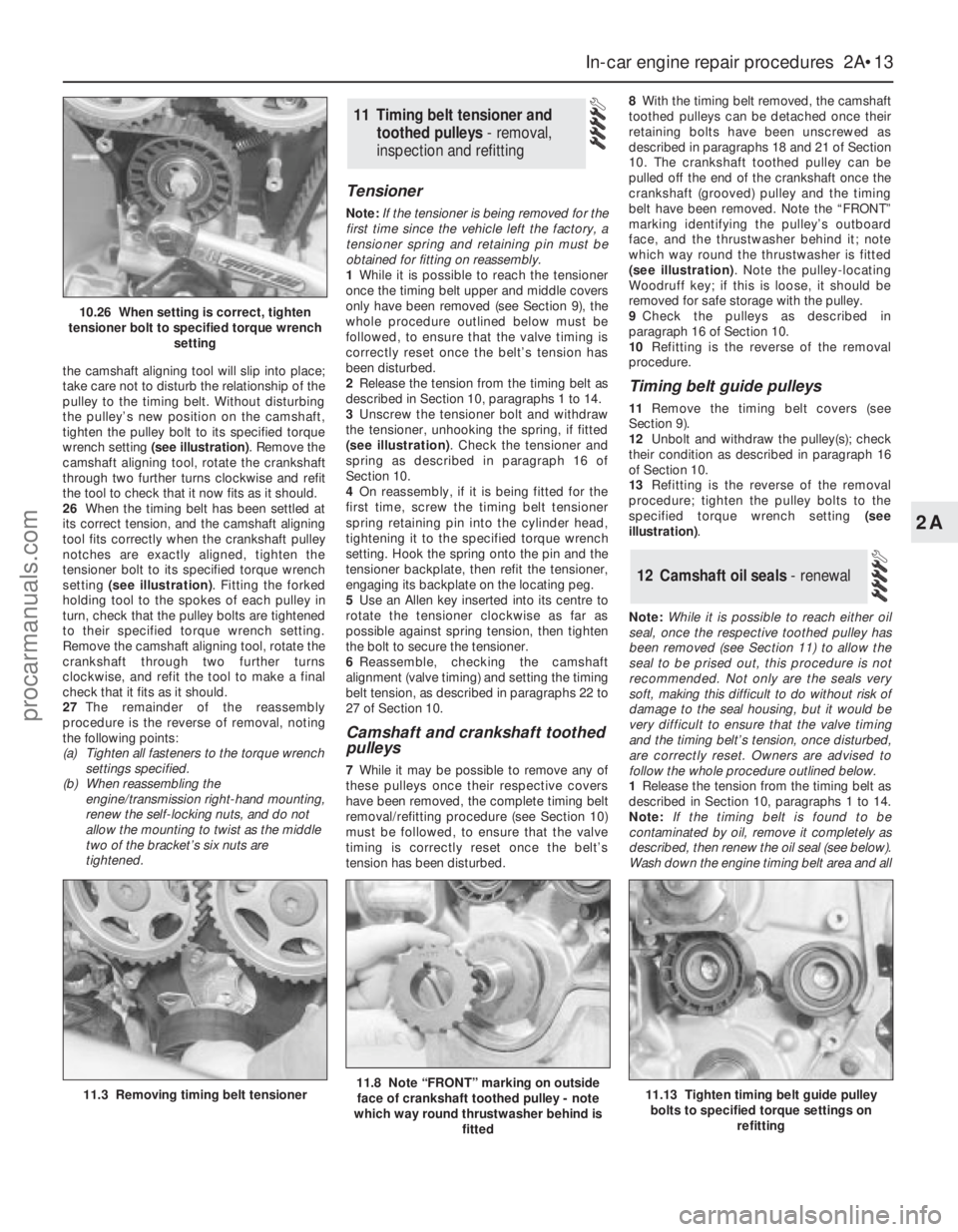
the camshaft aligning tool will slip into place;
take care not to disturb the relationship of the
pulley to the timing belt. Without disturbing
the pulley’s new position on the camshaft,
tighten the pulley bolt to its specified torque
wrench setting (see illustration). Remove the
camshaft aligning tool, rotate the crankshaft
through two further turns clockwise and refit
the tool to check that it now fits as it should.
26When the timing belt has been settled at
its correct tension, and the camshaft aligning
tool fits correctly when the crankshaft pulley
notches are exactly aligned, tighten the
tensioner bolt to its specified torque wrench
setting (see illustration). Fitting the forked
holding tool to the spokes of each pulley in
turn, check that the pulley bolts are tightened
to their specified torque wrench setting.
Remove the camshaft aligning tool, rotate the
crankshaft through two further turns
clockwise, and refit the tool to make a final
check that it fits as it should.
27The remainder of the reassembly
procedure is the reverse of removal, noting
the following points:
(a) Tighten all fasteners to the torque wrench
settings specified.
(b) When reassembling the
engine/transmission right-hand mounting,
renew the self-locking nuts, and do not
allow the mounting to twist as the middle
two of the bracket’s six nuts are
tightened.
Tensioner
Note:If the tensioner is being removed for the
first time since the vehicle left the factory, a
tensioner spring and retaining pin must be
obtained for fitting on reassembly.
1While it is possible to reach the tensioner
once the timing belt upper and middle covers
only have been removed (see Section 9), the
whole procedure outlined below must be
followed, to ensure that the valve timing is
correctly reset once the belt’s tension has
been disturbed.
2Release the tension from the timing belt as
described in Section 10, paragraphs 1 to 14.
3Unscrew the tensioner bolt and withdraw
the tensioner, unhooking the spring, if fitted
(see illustration). Check the tensioner and
spring as described in paragraph 16 of
Section 10.
4On reassembly, if it is being fitted for the
first time, screw the timing belt tensioner
spring retaining pin into the cylinder head,
tightening it to the specified torque wrench
setting. Hook the spring onto the pin and the
tensioner backplate, then refit the tensioner,
engaging its backplate on the locating peg.
5Use an Allen key inserted into its centre to
rotate the tensioner clockwise as far as
possible against spring tension, then tighten
the bolt to secure the tensioner.
6Reassemble, checking the camshaft
alignment (valve timing) and setting the timing
belt tension, as described in paragraphs 22 to
27 of Section 10.
Camshaft and crankshaft toothed
pulleys
7While it may be possible to remove any of
these pulleys once their respective covers
have been removed, the complete timing belt
removal/refitting procedure (see Section 10)
must be followed, to ensure that the valve
timing is correctly reset once the belt’s
tension has been disturbed.8With the timing belt removed, the camshaft
toothed pulleys can be detached once their
retaining bolts have been unscrewed as
described in paragraphs 18 and 21 of Section
10. The crankshaft toothed pulley can be
pulled off the end of the crankshaft once the
crankshaft (grooved) pulley and the timing
belt have been removed. Note the “FRONT”
marking identifying the pulley’s outboard
face, and the thrustwasher behind it; note
which way round the thrustwasher is fitted
(see illustration). Note the pulley-locating
Woodruff key; if this is loose, it should be
removed for safe storage with the pulley.
9Check the pulleys as described in
paragraph 16 of Section 10.
10Refitting is the reverse of the removal
procedure.
Timing belt guide pulleys
11Remove the timing belt covers (see
Section 9).
12Unbolt and withdraw the pulley(s); check
their condition as described in paragraph 16
of Section 10.
13Refitting is the reverse of the removal
procedure; tighten the pulley bolts to the
specified torque wrench setting (see
illustration).
Note:While it is possible to reach either oil
seal, once the respective toothed pulley has
been removed (see Section 11) to allow the
seal to be prised out, this procedure is not
recommended. Not only are the seals very
soft, making this difficult to do without risk of
damage to the seal housing, but it would be
very difficult to ensure that the valve timing
and the timing belt’s tension, once disturbed,
are correctly reset. Owners are advised to
follow the whole procedure outlined below.
1Release the tension from the timing belt as
described in Section 10, paragraphs 1 to 14.
Note:If the timing belt is found to be
contaminated by oil, remove it completely as
described, then renew the oil seal (see below).
Wash down the engine timing belt area and all
12 Camshaft oil seals - renewal
11 Timing belt tensioner and
toothed pulleys - removal,
inspection and refitting
In-car engine repair procedures 2A•13
2A
11.3 Removing timing belt tensioner11.8 Note “FRONT” marking on outside
face of crankshaft toothed pulley - note
which way round thrustwasher behind is
fitted11.13 Tighten timing belt guide pulley
bolts to specified torque settings on
refitting
10.26 When setting is correct, tighten
tensioner bolt to specified torque wrench
setting
procarmanuals.com
Page 106 of 279
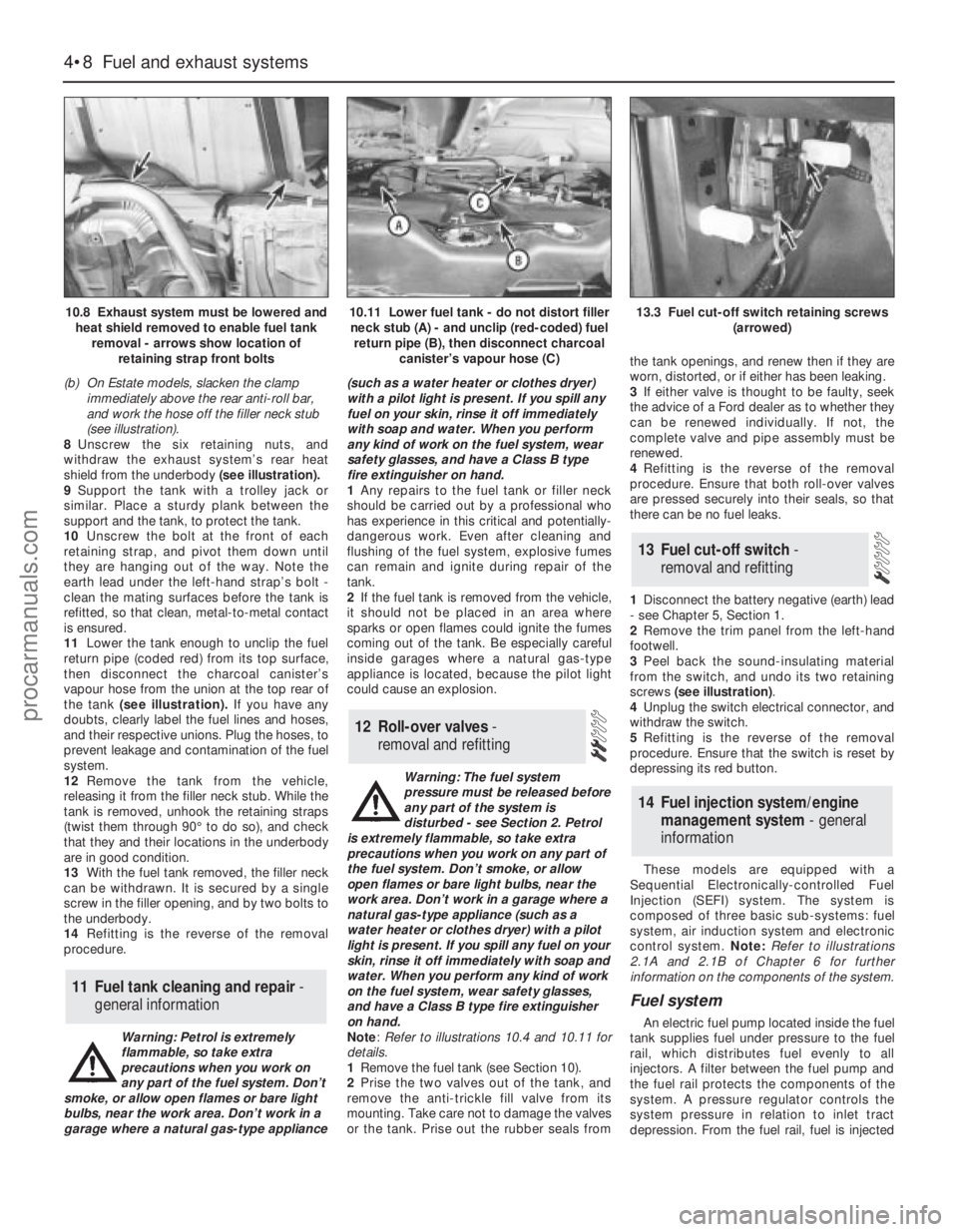
(b) On Estate models, slacken the clamp
immediately above the rear anti-roll bar,
and work the hose off the filler neck stub
(see illustration).
8Unscrew the six retaining nuts, and
withdraw the exhaust system’s rear heat
shield from the underbody (see illustration).
9Support the tank with a trolley jack or
similar. Place a sturdy plank between the
support and the tank, to protect the tank.
10Unscrew the bolt at the front of each
retaining strap, and pivot them down until
they are hanging out of the way. Note the
earth lead under the left-hand strap’s bolt -
clean the mating surfaces before the tank is
refitted, so that clean, metal-to-metal contact
is ensured.
11Lower the tank enough to unclip the fuel
return pipe (coded red) from its top surface,
then disconnect the charcoal canister’s
vapour hose from the union at the top rear of
the tank (see illustration). If you have any
doubts, clearly label the fuel lines and hoses,
and their respective unions. Plug the hoses, to
prevent leakage and contamination of the fuel
system.
12Remove the tank from the vehicle,
releasing it from the filler neck stub. While the
tank is removed, unhook the retaining straps
(twist them through 90° to do so), and check
that they and their locations in the underbody
are in good condition.
13With the fuel tank removed, the filler neck
can be withdrawn. It is secured by a single
screw in the filler opening, and by two bolts to
the underbody.
14Refitting is the reverse of the removal
procedure.
Warning: Petrol is extremely
flammable, so take extra
precautions when you work on
any part of the fuel system. Don’t
smoke, or allow open flames or bare light
bulbs, near the work area. Don’t work in a
garage where a natural gas-type appliance(such as a water heater or clothes dryer)
with a pilot light is present. If you spill any
fuel on your skin, rinse it off immediately
with soap and water. When you perform
any kind of work on the fuel system, wear
safety glasses, and have a Class B type
fire extinguisher on hand.
1Any repairs to the fuel tank or filler neck
should be carried out by a professional who
has experience in this critical and potentially-
dangerous work. Even after cleaning and
flushing of the fuel system, explosive fumes
can remain and ignite during repair of the
tank.
2If the fuel tank is removed from the vehicle,
it should not be placed in an area where
sparks or open flames could ignite the fumes
coming out of the tank. Be especially careful
inside garages where a natural gas-type
appliance is located, because the pilot light
could cause an explosion.
Warning: The fuel system
pressure must be released before
any part of the system is
disturbed - see Section 2. Petrol
is extremely flammable, so take extra
precautions when you work on any part of
the fuel system. Don’t smoke, or allow
open flames or bare light bulbs, near the
work area. Don’t work in a garage where a
natural gas-type appliance (such as a
water heater or clothes dryer) with a pilot
light is present. If you spill any fuel on your
skin, rinse it off immediately with soap and
water. When you perform any kind of work
on the fuel system, wear safety glasses,
and have a Class B type fire extinguisher
on hand.
Note: Refer to illustrations 10.4 and 10.11 for
details.
1Remove the fuel tank (see Section 10).
2Prise the two valves out of the tank, and
remove the anti-trickle fill valve from its
mounting. Take care not to damage the valves
or the tank. Prise out the rubber seals fromthe tank openings, and renew then if they are
worn, distorted, or if either has been leaking.
3If either valve is thought to be faulty, seek
the advice of a Ford dealer as to whether they
can be renewed individually. If not, the
complete valve and pipe assembly must be
renewed.
4Refitting is the reverse of the removal
procedure. Ensure that both roll-over valves
are pressed securely into their seals, so that
there can be no fuel leaks.
1Disconnect the battery negative (earth) lead
- see Chapter 5, Section 1.
2Remove the trim panel from the left-hand
footwell.
3Peel back the sound-insulating material
from the switch, and undo its two retaining
screws (see illustration).
4Unplug the switch electrical connector, and
withdraw the switch.
5Refitting is the reverse of the removal
procedure. Ensure that the switch is reset by
depressing its red button.
These models are equipped with a
Sequential Electronically-controlled Fuel
Injection (SEFI) system. The system is
composed of three basic sub-systems: fuel
system, air induction system and electronic
control system. Note:Refer to illustrations
2.1A and 2.1B of Chapter 6 for further
information on the components of the system.
Fuel system
An electric fuel pump located inside the fuel
tank supplies fuel under pressure to the fuel
rail, which distributes fuel evenly to all
injectors. A filter between the fuel pump and
the fuel rail protects the components of the
system. A pressure regulator controls the
system pressure in relation to inlet tract
depression. From the fuel rail, fuel is injected
14 Fuel injection system/engine
management system - general
information
13 Fuel cut-off switch -
removal and refitting
12 Roll-over valves -
removal and refitting
11 Fuel tank cleaning and repair -
general information
4•8 Fuel and exhaust systems
10.8 Exhaust system must be lowered and
heat shield removed to enable fuel tank
removal - arrows show location of
retaining strap front bolts10.11 Lower fuel tank - do not distort filler
neck stub (A) - and unclip (red-coded) fuel
return pipe (B), then disconnect charcoal
canister’s vapour hose (C)13.3 Fuel cut-off switch retaining screws
(arrowed)
procarmanuals.com
Page 115 of 279
5Undo the sensor’s retaining screw and
withdraw the sensor. The sensor’s bracket
cannot be unbolted from the cylinder
block/crankcase unless the transmission and
flywheel/driveplate have been removed (see
Chapter 2).
6Refitting is the reverse of the removal
procedure.
General information
The charging system includes the
alternator, an internal voltage regulator, a no-
charge (or “ignition”) warning light, the
battery, and the wiring between all the
components. The charging system supplies
electrical power for the ignition system, the
lights, the radio, etc. The alternator is driven
by the auxiliary drivebelt at the front (right-
hand end) of the engine.
The purpose of the voltage regulator is to
limit the alternator’s voltage to a preset value.
This prevents power surges, circuit overloads,
etc., during peak voltage output.
The charging system doesn’t ordinarily
require periodic maintenance. However, the
drivebelt, battery and wires and connections
should be inspected at the intervals outlined
in Chapter 1.
The dashboard warning light should come
on when the ignition key is turned to positions
“II” or “III”, then should go off immediately the
engine starts. If it remains on, or if it comes on
while the engine is running, there is a
malfunction in the charging system (see
Section 11). If the light does not come on
when the ignition key is turned, and the bulb is
sound (see Chapter 12), there is a fault in the
alternator.
Precautions
Be very careful when making electrical
circuit connections to a vehicle equipped with
an alternator, and note the following:
(a) When reconnecting wires to the alternator
from the battery, be sure to note the
polarity.
(b) Before using arc-welding equipment to
repair any part of the vehicle, disconnect
the wires from the alternator and the
battery terminals.
(c) Never start the engine with a battery
charger connected.
(d) Always disconnect both battery leads
before using a battery charger.
(e) The alternator is driven by an engine
drivebelt which could cause serious injury
if your hand, hair or clothes become
entangled in it with the engine running.
(f) Because the alternator is connected
directly to the battery, it could arc or
cause a fire if overloaded or shorted-out.
(g) Wrap a plastic bag over the alternator,
and secure it with rubber bands, beforesteam-cleaning or pressure-washing the
engine.
(h) Never disconnect the alternator terminals
while the engine is running.
1If a malfunction occurs in the charging
circuit, don’t automatically assume that the
alternator is causing the problem. First check
the following items:
(a) Check the tension and condition of the
auxiliary drivebelt - renew it if it is worn or
deteriorated (see Chapter 1).
(b) Ensure the alternator mounting bolts and
nuts are tight.
(c) Inspect the alternator wiring harness and
the electrical connections at the
alternator; they must be in good
condition, and tight.
(d) Check the large main fuses in the engine
compartment (see Chapter 12). If any is
blown, determine the cause, repair the
circuit and renew the fuse (the vehicle
won’t start and/or the accessories won’t
work if the fuse is blown).
(e) Start the engine and check the alternator
for abnormal noises - for example, a
shrieking or squealing sound may indicate
a badly-worn bearing or brush.
(f) Make sure that the battery is fully-charged
- one bad cell in a battery can cause
overcharging by the alternator.
(g) Disconnect the battery leads (negative
first, then positive). Inspect the battery
posts and the lead clamps for corrosion.
Clean them thoroughly if necessary (see
Section 3 and Chapter 1). Reconnect the
lead to the negative terminal.
(h) With the ignition and all accessories
switched off, insert a test light between
the battery negative post and the
disconnected negative lead clamp:
(1) If the test light does not come on, re-
attach the clamp and proceed to the next
step.
(2) If the test light comes on, there is a short
in the electrical system of the vehicle. The
short must be repaired before the
charging system can be checked.
(3) To find the short, disconnect the
alternator wiring harness:
(a) If the light goes out, the alternator is
at fault.
(b) If the light stays on, remove each fuse
until it goes out - this will tell you
which component is short-circuited.
2Using a voltmeter, check the battery
voltage with the engine off. It should be
approximately 12 volts.
3Start the engine and check the battery
voltage again. Increase engine speed until the
voltmeter reading remains steady; it should
now be approximately 13.5 to 14.6 volts.
4Switch on as many electrical accessories
(eg the headlights, heated rear window andheater blower) as possible, and check that the
alternator maintains the regulated voltage at
around 13 to 14 volts. The voltage may drop
and then come back up; it may also be
necessary to increase engine speed slightly,
even if the charging system is working
properly.
5If the voltage reading is greater than the
specified charging voltage, renew the voltage
regulator (see Section 13).
6If the voltmeter reading is less than that
specified, the fault may be due to worn
brushes, weak brush springs, a faulty voltage
regulator, a faulty diode, a severed phase
winding, or worn or damaged slip rings. The
brushes and slip rings may be checked (see
Section 13), but if the fault persists, the
alternator should be renewed or taken to an
auto-electrician for testing and repair.
1Disconnect the battery negative (earth) lead
- see Section 1.
2Remove the plenum chamber (see Chap-
ter 4).
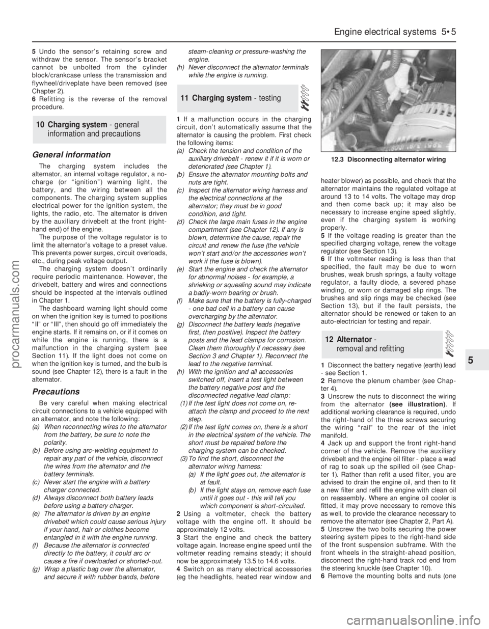
3Unscrew the nuts to disconnect the wiring
from the alternator (see illustration). If
additional working clearance is required, undo
the right-hand of the three screws securing
the wiring “rail” to the rear of the inlet
manifold.
4Jack up and support the front right-hand
corner of the vehicle. Remove the auxiliary
drivebelt and the engine oil filter - place a wad
of rag to soak up the spilled oil (see Chap-
ter 1). Rather than refit a used filter, you are
advised to drain the engine oil, and then to fit
a new filter and refill the engine with clean oil
on reassembly. Where an engine oil cooler is
fitted, it may prove necessary to remove this
as well, to provide the clearance necessary to
remove the alternator (see Chapter 2, Part A).
5Unscrew the two bolts securing the power
steering system pipes to the right-hand side
of the front suspension subframe. With the
front wheels in the straight-ahead position,
disconnect the right-hand track rod end from
the steering knuckle (see Chapter 10).
6Remove the mounting bolts and nuts (one
12 Alternator-
removal and refitting
11 Charging system- testing
10 Charging system - general
information and precautions
Engine electrical systems 5•5
5
12.3 Disconnecting alternator wiring
procarmanuals.com
Page 134 of 279
Refitting and adjustment
5With the switch removed, reset it by fully
extending its plunger.
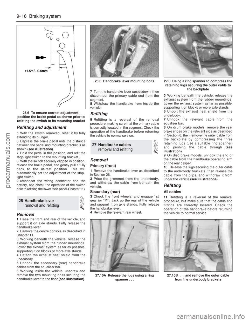
6Depress the brake pedal until the distance
between the pedal and mounting bracket is as
shown (see illustration).
7Hold the pedal in this position, and refit the
stop-light switch to the mounting bracket .
8With the switch securely clipped in position,
release the brake pedal, and gently pull it fully
back to the at-rest position. This will
automatically set the adjustment of the stop-
light switch.
9reconnect the wiring connector and the
battery, and check the operation of the switch
prior to refitting the lower facia panel (Chapter 11).
Removal
1Raise the front and rear of the vehicle, and
support it on axle stands. Fully release the
handbrake lever.
2Remove the centre console as described in
Chapter 11.
3Working beneath the vehicle, release the
exhaust system from the rubber mountings.
Lower the exhaust system as far as possible,
supporting it on blocks or more axle stands.
4Detach the exhaust heat shield from the
underbody.
5Unhook the secondary (rear) handbrake
cables from the equaliser bar.
6Working inside the vehicle, unscrew and
remove the two mounting bolts securing the
handbrake lever to the floor (see illustration).7Turn the handbrake lever upsidedown, then
disconnect the primary cable end from the
segment.
8Withdraw the handbrake from inside the
vehicle.
Refitting
9Refitting is a reversal of the removal
procedure, making sure that the primary cable
is correctly located in the segment. Check the
operation of the handbrake before returning
the vehicle to normal service.
Removal
Primary (front)
1Remove the handbrake lever as described
in Section 26.
2Prise the grommet from the underbody,
and withdraw the cable from beneath the
vehicle.
Secondary (rear)
3Chock the front wheels, and engage 1st
gear (or “P”). Jack up the rear of the vehicle
and support it on axle stands. Fully release
the handbrake lever.
4Remove the relevant rear wheel.5Working beneath the vehicle, release the
exhaust system from the rubber mountings.
Lower the exhaust system as far as possible,
supporting it on blocks or more axle stands.
6Unbolt the exhaust heat shield from the
underbody.
7Unhook the relevant cable from the
equaliser bar.
8On drum brake models, remove the rear
brake shoes on the relevant side as described
in Section 6, then remove the outer cable from
the backplate by compressing the three
retaining lugs (use a suitable ring spanner)
and pushing the cable through (see
illustration).
9On disc brake models, unhook the end of
the cable from the handbrake operating arm
on the rear caliper.
10Release the lugs securing the outer cable
to the underbody brackets, then release the
cable from the clips, and withdraw it from
under the vehicle (see illustrations).
Refitting
All cables
11Refitting is a reversal of the removal
procedure, but make sure that the cable end
fittings are correctly located. Check the
operation of the handbrake before returning
the vehicle to normal service.
27 Handbrake cables -
removal and refitting
26 Handbrake lever -
removal and refitting
9•16 Braking system
25.6 To ensure correct adjustment,
position the brake pedal as shown prior to
refitting the switch to its mounting bracket
26.6 Handbrake lever mounting bolts27.8 Using a ring spanner to compress the
retaining lugs securing the outer cable to
the backplate
27.10A Release the lugs using a ring
spanner . . .27.10B . . . and remove the outer cable
from the underbody brackets
procarmanuals.com
Page 155 of 279
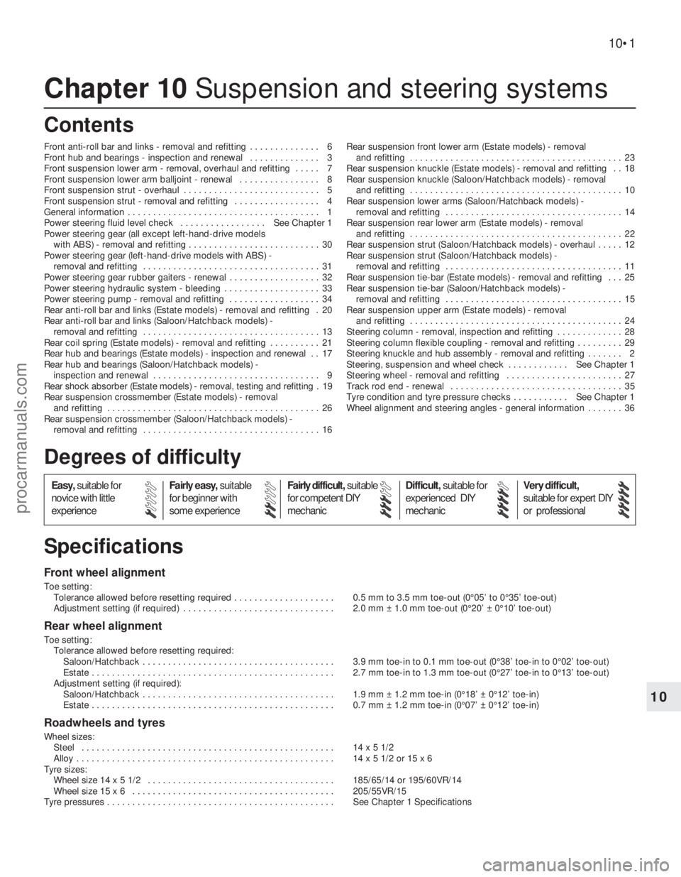
Chapter 10 Suspension and steering systems
Front anti-roll bar and links - removal and refitting . . . . . . . . . . . . . . 6
Front hub and bearings - inspection and renewal . . . . . . . . . . . . . . 3
Front suspension lower arm - removal, overhaul and refitting . . . . . 7
Front suspension lower arm balljoint - renewal . . . . . . . . . . . . . . . . 8
Front suspension strut - overhaul . . . . . . . . . . . . . . . . . . . . . . . . . . . 5
Front suspension strut - removal and refitting . . . . . . . . . . . . . . . . . 4
General information . . . . . . . . . . . . . . . . . . . . . . . . . . . . . . . . . . . . . . 1
Power steering fluid level check . . . . . . . . . . . . . . . . . See Chapter 1
Power steering gear (all except left-hand-drive models
with ABS) - removal and refitting . . . . . . . . . . . . . . . . . . . . . . . . . . 30
Power steering gear (left-hand-drive models with ABS) -
removal and refitting . . . . . . . . . . . . . . . . . . . . . . . . . . . . . . . . . . . 31
Power steering gear rubber gaiters - renewal . . . . . . . . . . . . . . . . . . 32
Power steering hydraulic system - bleeding . . . . . . . . . . . . . . . . . . . 33
Power steering pump - removal and refitting . . . . . . . . . . . . . . . . . . 34
Rear anti-roll bar and links (Estate models) - removal and refitting . 20
Rear anti-roll bar and links (Saloon/Hatchback models) -
removal and refitting . . . . . . . . . . . . . . . . . . . . . . . . . . . . . . . . . . . 13
Rear coil spring (Estate models) - removal and refitting . . . . . . . . . . 21
Rear hub and bearings (Estate models) - inspection and renewal . . 17
Rear hub and bearings (Saloon/Hatchback models) -
inspection and renewal . . . . . . . . . . . . . . . . . . . . . . . . . . . . . . . . . 9
Rear shock absorber (Estate models) - removal, testing and refitting . 19
Rear suspension crossmember (Estate models) - removal
and refitting . . . . . . . . . . . . . . . . . . . . . . . . . . . . . . . . . . . . . . . . . . 26
Rear suspension crossmember (Saloon/Hatchback models) -
removal and refitting . . . . . . . . . . . . . . . . . . . . . . . . . . . . . . . . . . . 16Rear suspension front lower arm (Estate models) - removal
and refitting . . . . . . . . . . . . . . . . . . . . . . . . . . . . . . . . . . . . . . . . . . 23
Rear suspension knuckle (Estate models) - removal and refitting . . 18
Rear suspension knuckle (Saloon/Hatchback models) - removal
and refitting . . . . . . . . . . . . . . . . . . . . . . . . . . . . . . . . . . . . . . . . . . 10
Rear suspension lower arms (Saloon/Hatchback models) -
removal and refitting . . . . . . . . . . . . . . . . . . . . . . . . . . . . . . . . . . . 14
Rear suspension rear lower arm (Estate models) - removal
and refitting . . . . . . . . . . . . . . . . . . . . . . . . . . . . . . . . . . . . . . . . . . 22
Rear suspension strut (Saloon/Hatchback models) - overhaul . . . . . 12
Rear suspension strut (Saloon/Hatchback models) -
removal and refitting . . . . . . . . . . . . . . . . . . . . . . . . . . . . . . . . . . . 11
Rear suspension tie-bar (Estate models) - removal and refitting . . . 25
Rear suspension tie-bar (Saloon/Hatchback models) -
removal and refitting . . . . . . . . . . . . . . . . . . . . . . . . . . . . . . . . . . . 15
Rear suspension upper arm (Estate models) - removal
and refitting . . . . . . . . . . . . . . . . . . . . . . . . . . . . . . . . . . . . . . . . . . 24
Steering column - removal, inspection and refitting . . . . . . . . . . . . . 28
Steering column flexible coupling - removal and refitting . . . . . . . . . 29
Steering knuckle and hub assembly - removal and refitting . . . . . . . 2
Steering, suspension and wheel check . . . . . . . . . . . . See Chapter 1
Steering wheel - removal and refitting . . . . . . . . . . . . . . . . . . . . . . . 27
Track rod end - renewal . . . . . . . . . . . . . . . . . . . . . . . . . . . . . . . . . . 35
Tyre condition and tyre pressure checks . . . . . . . . . . . See Chapter 1
Wheel alignment and steering angles - general information . . . . . . . 36
Front wheel alignment
Toe setting:
Tolerance allowed before resetting required . . . . . . . . . . . . . . . . . . . . 0.5 mm to 3.5 mm toe-out (0°05’ to 0°35’ toe-out)
Adjustment setting (if required) . . . . . . . . . . . . . . . . . . . . . . . . . . . . . . 2.0 mm ± 1.0 mm toe-out (0°20’ ± 0°10’ toe-out)
Rear wheel alignment
Toe setting:
Tolerance allowed before resetting required:
Saloon/Hatchback . . . . . . . . . . . . . . . . . . . . . . . . . . . . . . . . . . . . . . 3.9 mm toe-in to 0.1 mm toe-out (0°38’ toe-in to 0°02’ toe-out)
Estate . . . . . . . . . . . . . . . . . . . . . . . . . . . . . . . . . . . . . . . . . . . . . . . . 2.7 mm toe-in to 1.3 mm toe-out (0°27’ toe-in to 0°13’ toe-out)
Adjustment setting (if required):
Saloon/Hatchback . . . . . . . . . . . . . . . . . . . . . . . . . . . . . . . . . . . . . . 1.9 mm ± 1.2 mm toe-in (0°18’ ± 0°12’ toe-in)
Estate . . . . . . . . . . . . . . . . . . . . . . . . . . . . . . . . . . . . . . . . . . . . . . . . 0.7 mm ± 1.2 mm toe-in (0°07’ ± 0°12’ toe-in)
Roadwheels and tyres
Wheel sizes:
Steel . . . . . . . . . . . . . . . . . . . . . . . . . . . . . . . . . . . . . . . . . . . . . . . . . . 14 x 5 1/2
Alloy . . . . . . . . . . . . . . . . . . . . . . . . . . . . . . . . . . . . . . . . . . . . . . . . . . . 14 x 5 1/2 or 15 x 6
Tyre sizes:
Wheel size 14 x 5 1/2 . . . . . . . . . . . . . . . . . . . . . . . . . . . . . . . . . . . . . 185/65/14 or 195/60VR/14
Wheel size 15 x 6 . . . . . . . . . . . . . . . . . . . . . . . . . . . . . . . . . . . . . . . . 205/55VR/15
Tyre pressures . . . . . . . . . . . . . . . . . . . . . . . . . . . . . . . . . . . . . . . . . . . . . See Chapter 1 Specifications
10•1
Easy,suitable for
novice with little
experienceFairly easy,suitable
for beginner with
some experienceFairly difficult,suitable
for competent DIY
mechanicDifficult,suitable for
experienced DIY
mechanicVery difficult,
suitable for expert DIY
or professional
Degrees of difficulty
Specifications Contents
10
procarmanuals.com
Page 177 of 279
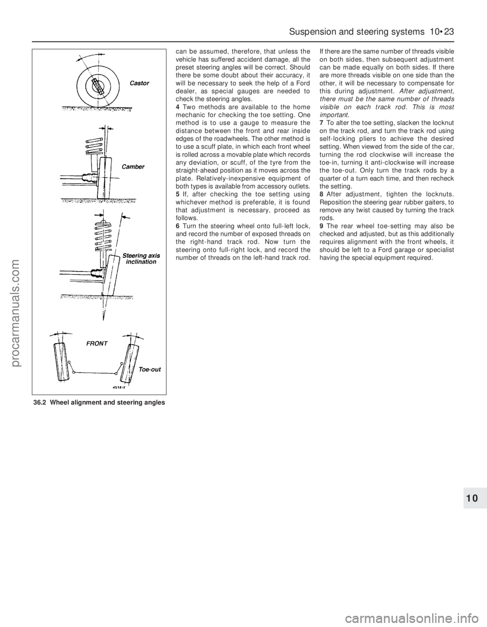
can be assumed, therefore, that unless the
vehicle has suffered accident damage, all the
preset steering angles will be correct. Should
there be some doubt about their accuracy, it
will be necessary to seek the help of a Ford
dealer, as special gauges are needed to
check the steering angles.
4Two methods are available to the home
mechanic for checking the toe setting. One
method is to use a gauge to measure the
distance between the front and rear inside
edges of the roadwheels. The other method is
to use a scuff plate, in which each front wheel
is rolled across a movable plate which records
any deviation, or scuff, of the tyre from the
straight-ahead position as it moves across the
plate. Relatively-inexpensive equipment of
both types is available from accessory outlets.
5If, after checking the toe setting using
whichever method is preferable, it is found
that adjustment is necessary, proceed as
follows.
6Turn the steering wheel onto full-left lock,
and record the number of exposed threads on
the right-hand track rod. Now turn the
steering onto full-right lock, and record the
number of threads on the left-hand track rod.If there are the same number of threads visible
on both sides, then subsequent adjustment
can be made equally on both sides. If there
are more threads visible on one side than the
other, it will be necessary to compensate for
this during adjustment. After adjustment,
there must be the same number of threads
visible on each track rod. This is most
important.
7To alter the toe setting, slacken the locknut
on the track rod, and turn the track rod using
self-locking pliers to achieve the desired
setting. When viewed from the side of the car,
turning the rod clockwise will increase the
toe-in, turning it anti-clockwise will increase
the toe-out. Only turn the track rods by a
quarter of a turn each time, and then recheck
the setting.
8After adjustment, tighten the locknuts.
Reposition the steering gear rubber gaiters, to
remove any twist caused by turning the track
rods.
9The rear wheel toe-setting may also be
checked and adjusted, but as this additionally
requires alignment with the front wheels, it
should be left to a Ford garage or specialist
having the special equipment required.
Suspension and steering systems 10•23
10
36.2 Wheel alignment and steering angles
procarmanuals.com
Page 178 of 279
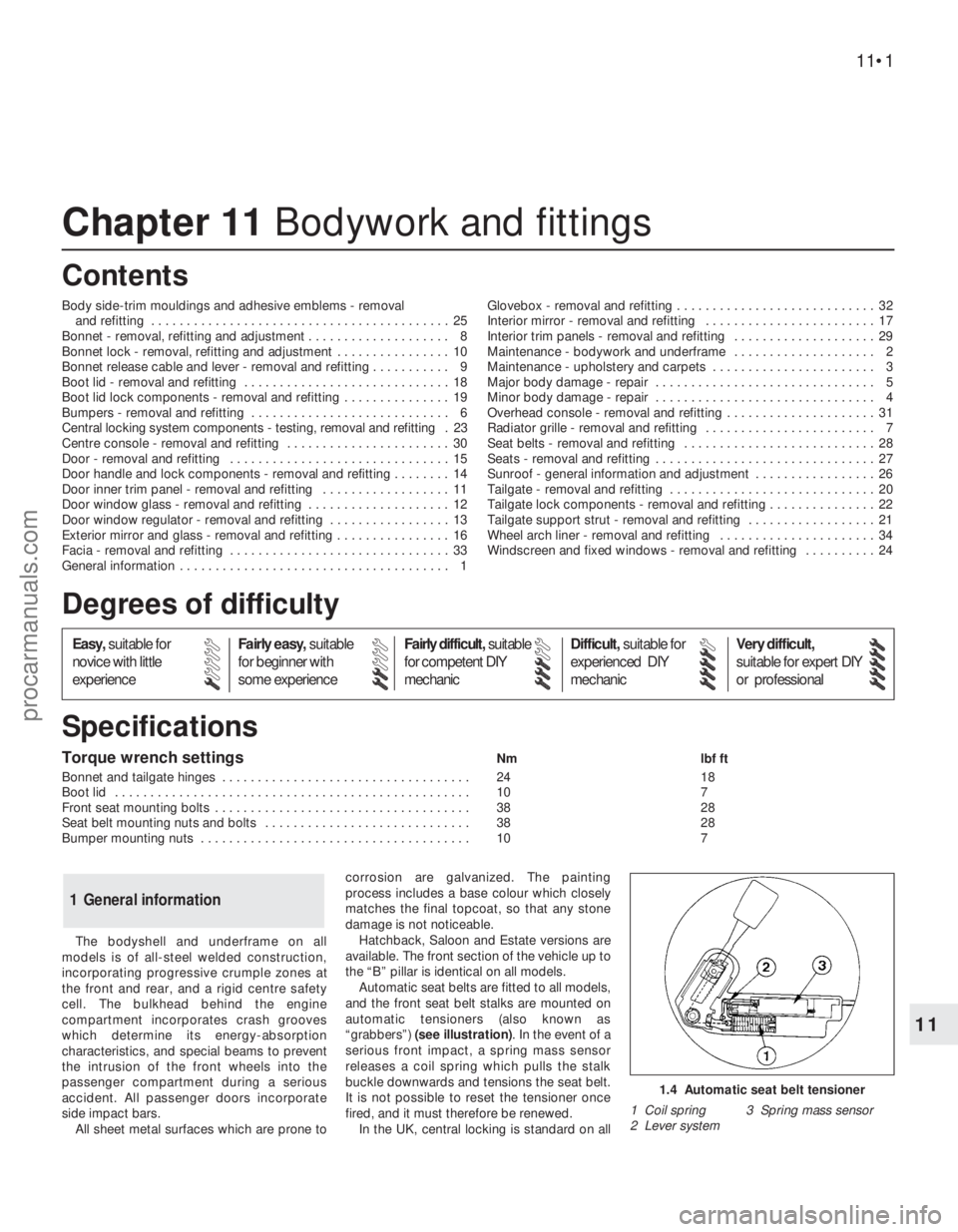
Chapter 11 Bodywork and fittings
Body side-trim mouldings and adhesive emblems - removal
and refitting . . . . . . . . . . . . . . . . . . . . . . . . . . . . . . . . . . . . . . . . . . 25
Bonnet - removal, refitting and adjustment . . . . . . . . . . . . . . . . . . . . 8
Bonnet lock - removal, refitting and adjustment . . . . . . . . . . . . . . . . 10
Bonnet release cable and lever - removal and refitting . . . . . . . . . . . 9
Boot lid - removal and refitting . . . . . . . . . . . . . . . . . . . . . . . . . . . . . 18
Boot lid lock components - removal and refitting . . . . . . . . . . . . . . . 19
Bumpers - removal and refitting . . . . . . . . . . . . . . . . . . . . . . . . . . . . 6
Central locking system components - testing, removal and refitting . 23
Centre console - removal and refitting . . . . . . . . . . . . . . . . . . . . . . . 30
Door - removal and refitting . . . . . . . . . . . . . . . . . . . . . . . . . . . . . . . 15
Door handle and lock components - removal and refitting . . . . . . . . 14
Door inner trim panel - removal and refitting . . . . . . . . . . . . . . . . . . 11
Door window glass - removal and refitting . . . . . . . . . . . . . . . . . . . . 12
Door window regulator - removal and refitting . . . . . . . . . . . . . . . . . 13
Exterior mirror and glass - removal and refitting . . . . . . . . . . . . . . . . 16
Facia - removal and refitting . . . . . . . . . . . . . . . . . . . . . . . . . . . . . . . 33
General information . . . . . . . . . . . . . . . . . . . . . . . . . . . . . . . . . . . . . . 1Glovebox - removal and refitting . . . . . . . . . . . . . . . . . . . . . . . . . . . . 32
Interior mirror - removal and refitting . . . . . . . . . . . . . . . . . . . . . . . . 17
Interior trim panels - removal and refitting . . . . . . . . . . . . . . . . . . . . 29
Maintenance - bodywork and underframe . . . . . . . . . . . . . . . . . . . . 2
Maintenance - upholstery and carpets . . . . . . . . . . . . . . . . . . . . . . . 3
Major body damage - repair . . . . . . . . . . . . . . . . . . . . . . . . . . . . . . . 5
Minor body damage - repair . . . . . . . . . . . . . . . . . . . . . . . . . . . . . . . 4
Overhead console - removal and refitting . . . . . . . . . . . . . . . . . . . . . 31
Radiator grille - removal and refitting . . . . . . . . . . . . . . . . . . . . . . . . 7
Seat belts - removal and refitting . . . . . . . . . . . . . . . . . . . . . . . . . . . 28
Seats - removal and refitting . . . . . . . . . . . . . . . . . . . . . . . . . . . . . . . 27
Sunroof - general information and adjustment . . . . . . . . . . . . . . . . . 26
Tailgate - removal and refitting . . . . . . . . . . . . . . . . . . . . . . . . . . . . . 20
Tailgate lock components - removal and refitting . . . . . . . . . . . . . . . 22
Tailgate support strut - removal and refitting . . . . . . . . . . . . . . . . . . 21
Wheel arch liner - removal and refitting . . . . . . . . . . . . . . . . . . . . . . 34
Windscreen and fixed windows - removal and refitting . . . . . . . . . . 24
Torque wrench settingsNm lbf ft
Bonnet and tailgate hinges . . . . . . . . . . . . . . . . . . . . . . . . . . . . . . . . . . . 24 18
Boot lid . . . . . . . . . . . . . . . . . . . . . . . . . . . . . . . . . . . . . . . . . . . . . . . . . . 10 7
Front seat mounting bolts . . . . . . . . . . . . . . . . . . . . . . . . . . . . . . . . . . . . 38 28
Seat belt mounting nuts and bolts . . . . . . . . . . . . . . . . . . . . . . . . . . . . . 38 28
Bumper mounting nuts . . . . . . . . . . . . . . . . . . . . . . . . . . . . . . . . . . . . . . 10 7
11•1
Easy,suitable for
novice with little
experienceFairly easy,suitable
for beginner with
some experienceFairly difficult,suitable
for competent DIY
mechanicDifficult,suitable for
experienced DIY
mechanicVery difficult,
suitable for expert DIY
or professional
Degrees of difficulty
Specifications Contents
11
The bodyshell and underframe on all
models is of all-steel welded construction,
incorporating progressive crumple zones at
the front and rear, and a rigid centre safety
cell. The bulkhead behind the engine
compartment incorporates crash grooves
which determine its energy-absorption
characteristics, and special beams to prevent
the intrusion of the front wheels into the
passenger compartment during a serious
accident. All passenger doors incorporate
side impact bars.
All sheet metal surfaces which are prone tocorrosion are galvanized. The painting
process includes a base colour which closely
matches the final topcoat, so that any stone
damage is not noticeable.
Hatchback, Saloon and Estate versions are
available. The front section of the vehicle up to
the “B” pillar is identical on all models.
Automatic seat belts are fitted to all models,
and the front seat belt stalks are mounted on
automatic tensioners (also known as
“grabbers”) (see illustration). In the event of a
serious front impact, a spring mass sensor
releases a coil spring which pulls the stalk
buckle downwards and tensions the seat belt.
It is not possible to reset the tensioner once
fired, and it must therefore be renewed.
In the UK, central locking is standard on all
1 General information
1.4 Automatic seat belt tensioner
1 Coil spring 3 Spring mass sensor
2 Lever system
procarmanuals.com
Page 179 of 279
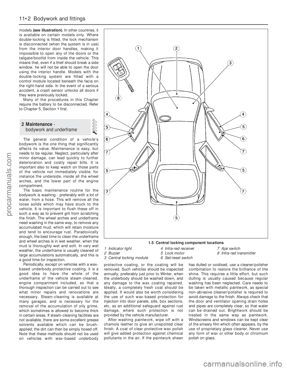
models (see illustration). In other countries, it
is available on certain models only. Where
double-locking is fitted, the lock mechanism
is disconnected (when the system is in use)
from the interior door handles, making it
impossible to open any of the doors or the
tailgate/bootlid from inside the vehicle. This
means that, even if a thief should break a side
window, he will not be able to open the door
using the interior handle. Models with the
double-locking system are fitted with a
control module located beneath the facia on
the right-hand side. In the event of a serious
accident, a crash sensor unlocks all doors if
they were previously locked.
Many of the procedures in this Chapter
require the battery to be disconnected. Refer
to Chapter 5, Section 1 first.
The general condition of a vehicle’s
bodywork is the one thing that significantly
affects its value. Maintenance is easy, but
needs to be regular. Neglect, particularly after
minor damage, can lead quickly to further
deterioration and costly repair bills. It is
important also to keep watch on those parts
of the vehicle not immediately visible, for
instance the underside, inside all the wheel
arches, and the lower part of the engine
compartment.
The basic maintenance routine for the
bodywork is washing - preferably with a lot of
water, from a hose. This will remove all the
loose solids which may have stuck to the
vehicle. It is important to flush these off in
such a way as to prevent grit from scratching
the finish. The wheel arches and underframe
need washing in the same way, to remove any
accumulated mud, which will retain moisture
and tend to encourage rust. Paradoxically
enough, the best time to clean the underframe
and wheel arches is in wet weather, when the
mud is thoroughly wet and soft. In very wet
weather, the underframe is usually cleaned of
large accumulations automatically, and this is
a good time for inspection.
Periodically, except on vehicles with a wax-
based underbody protective coating, it is a
good idea to have the whole of the
underframe of the vehicle steam-cleaned,
engine compartment included, so that a
thorough inspection can be carried out to see
what minor repairs and renovations are
necessary. Steam-cleaning is available at
many garages, and is necessary for the
removal of the accumulation of oily grime,
which sometimes is allowed to become thick
in certain areas. If steam-cleaning facilities are
not available, there are some excellent grease
solvents available which can be brush-
applied; the dirt can then be simply hosed off.
Note that these methods should not be used
on vehicles with wax-based underbodyprotective coating, or the coating will be
removed. Such vehicles should be inspected
annually, preferably just prior to Winter, when
the underbody should be washed down, and
any damage to the wax coating repaired.
Ideally, a completely fresh coat should be
applied. It would also be worth considering
the use of such wax-based protection for
injection into door panels, sills, box sections,
etc, as an additional safeguard against rust
damage, where such protection is not
provided by the vehicle manufacturer.
After washing paintwork, wipe off with a
chamois leather to give an unspotted clear
finish. A coat of clear protective wax polish
will give added protection against chemical
pollutants in the air. If the paintwork sheenhas dulled or oxidised, use a cleaner/polisher
combination to restore the brilliance of the
shine. This requires a little effort, but such
dulling is usually caused because regular
washing has been neglected. Care needs to
be taken with metallic paintwork, as special
non-abrasive cleaner/polisher is required to
avoid damage to the finish. Always check that
the door and ventilator opening drain holes
and pipes are completely clear, so that water
can be drained out. Brightwork should be
treated in the same way as paintwork.
Windscreens and windows can be kept clear
of the smeary film which often appears, by the
use of proprietary glass cleaner. Never use
any form of wax or other body or chromium
polish on glass.
2 Maintenance -
bodywork and underframe
11•2 Bodywork and fittings
1.5 Central locking component locations
1 Indicator light
2 Buzzer
3 Central locking module4 Infra-red receiver
5 Lock motor
6 Set/reset switch7 Ajar switch
8 Infra-red transmitter
procarmanuals.com