1993 FORD MONDEO reset
[x] Cancel search: resetPage 188 of 279
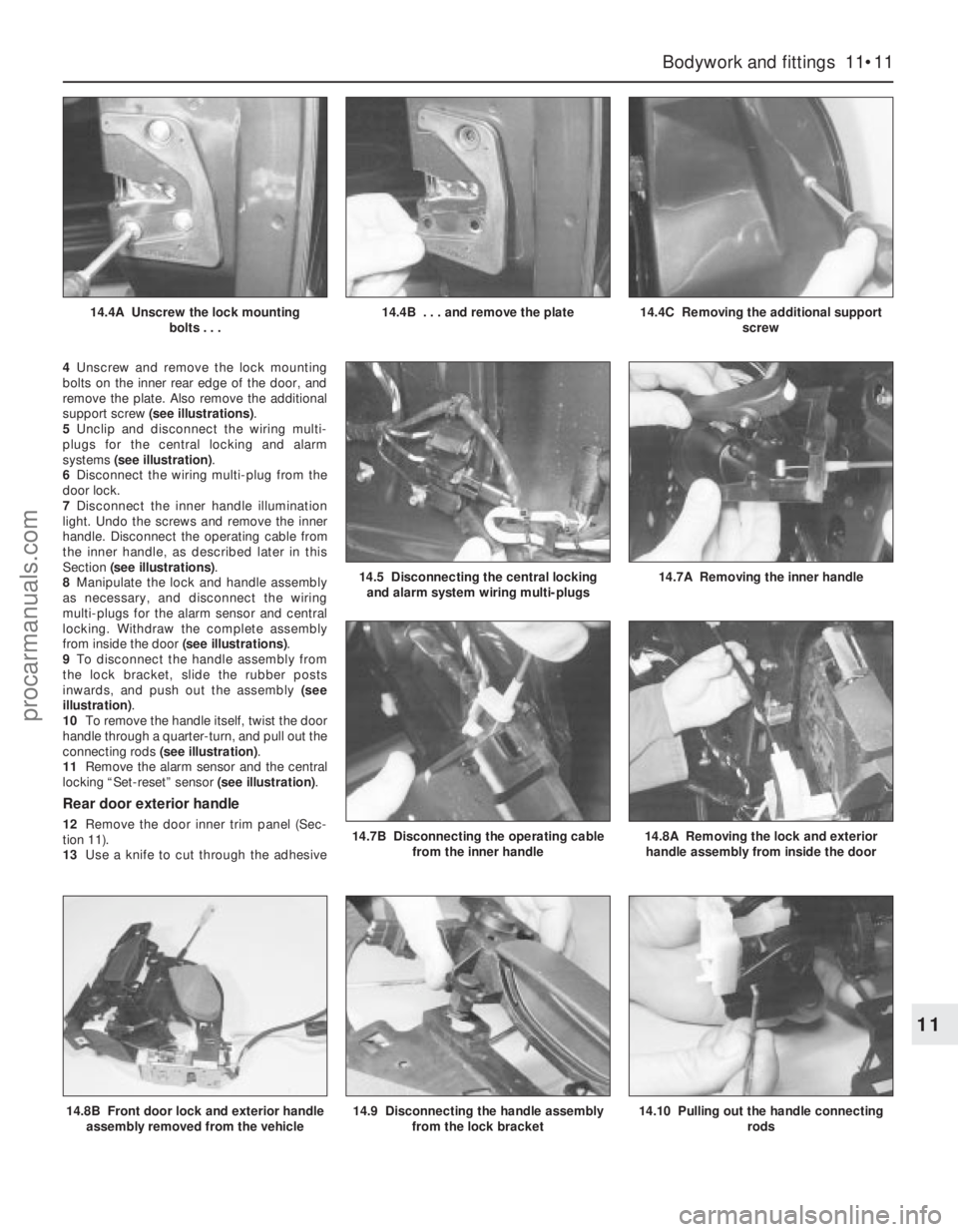
4Unscrew and remove the lock mounting
bolts on the inner rear edge of the door, and
remove the plate. Also remove the additional
support screw (see illustrations).
5Unclip and disconnect the wiring multi-
plugs for the central locking and alarm
systems (see illustration).
6Disconnect the wiring multi-plug from the
door lock.
7Disconnect the inner handle illumination
light. Undo the screws and remove the inner
handle. Disconnect the operating cable from
the inner handle, as described later in this
Section (see illustrations).
8Manipulate the lock and handle assembly
as necessary, and disconnect the wiring
multi-plugs for the alarm sensor and central
locking. Withdraw the complete assembly
from inside the door (see illustrations).
9To disconnect the handle assembly from
the lock bracket, slide the rubber posts
inwards, and push out the assembly (see
illustration).
10To remove the handle itself, twist the door
handle through a quarter-turn, and pull out the
connecting rods (see illustration).
11Remove the alarm sensor and the central
locking “Set-reset” sensor (see illustration).
Rear door exterior handle
12Remove the door inner trim panel (Sec-
tion 11).
13Use a knife to cut through the adhesive
Bodywork and fittings 11•11
11
14.8B Front door lock and exterior handle
assembly removed from the vehicle14.9 Disconnecting the handle assembly
from the lock bracket14.10 Pulling out the handle connecting
rods
14.4A Unscrew the lock mounting
bolts . . .14.4B . . . and remove the plate14.4C Removing the additional support
screw
14.5 Disconnecting the central locking
and alarm system wiring multi-plugs14.7A Removing the inner handle
14.7B Disconnecting the operating cable
from the inner handle14.8A Removing the lock and exterior
handle assembly from inside the door
procarmanuals.com
Page 189 of 279
strip, so that the foam insulator can be peeled
back for access to the lock. Do notpeel back
the foam insulator without first cutting through
the adhesive strip. To ensure a good seal
when the insulator is pressed back, do not
touch the adhesive strip.
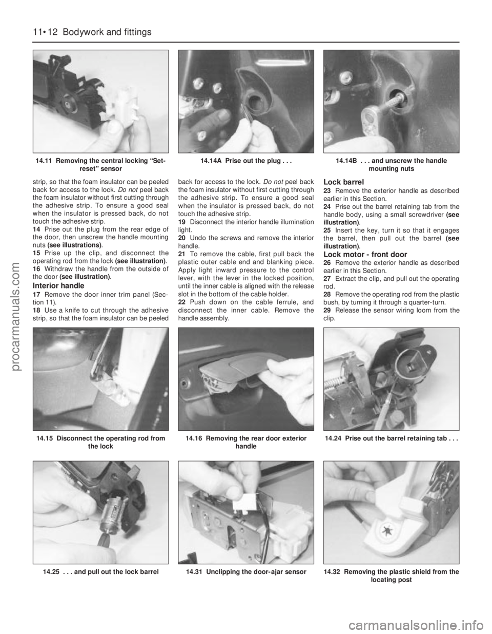
14Prise out the plug from the rear edge of
the door, then unscrew the handle mounting
nuts (see illustrations).
15Prise up the clip, and disconnect the
operating rod from the lock (see illustration).
16Withdraw the handle from the outside of
the door (see illustration).
Interior handle
17Remove the door inner trim panel (Sec-
tion 11).
18Use a knife to cut through the adhesive
strip, so that the foam insulator can be peeledback for access to the lock. Do notpeel back
the foam insulator without first cutting through
the adhesive strip. To ensure a good seal
when the insulator is pressed back, do not
touch the adhesive strip.
19Disconnect the interior handle illumination
light.
20Undo the screws and remove the interior
handle.
21To remove the cable, first pull back the
plastic outer cable end and blanking piece.
Apply light inward pressure to the control
lever, with the lever in the locked position,
until the inner cable is aligned with the release
slot in the bottom of the cable holder.
22Push down on the cable ferrule, and
disconnect the inner cable. Remove the
handle assembly.
Lock barrel
23Remove the exterior handle as described
earlier in this Section.
24Prise out the barrel retaining tab from the
handle body, using a small screwdriver (see
illustration).
25Insert the key, turn it so that it engages
the barrel, then pull out the barrel (see
illustration).
Lock motor - front door26Remove the exterior handle as described
earlier in this Section.
27Extract the clip, and pull out the operating
rod.
28Remove the operating rod from the plastic
bush, by turning it through a quarter-turn.
29Release the sensor wiring loom from the
clip.
11•12 Bodywork and fittings
14.11 Removing the central locking “Set-
reset” sensor14.14A Prise out the plug . . .14.14B . . . and unscrew the handle
mounting nuts
14.25 . . . and pull out the lock barrel14.31 Unclipping the door-ajar sensor14.32 Removing the plastic shield from the
locating post
14.15 Disconnect the operating rod from
the lock14.16 Removing the rear door exterior
handle14.24 Prise out the barrel retaining tab . . .
procarmanuals.com
Page 194 of 279
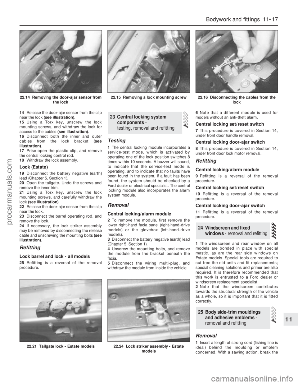
14Release the door-ajar sensor from the clip
near the lock (see illustration).
15Using a Torx key, unscrew the lock
mounting screws, and withdraw the lock for
access to the cables (see illustration).
16Disconnect both the inner and outer
cables from the lock bracket (see
illustration).
17Prise open the plastic clip, and remove
the central locking control rod.
18Withdraw the lock assembly.
Lock (Estate)
19Disconnect the battery negative (earth)
lead (Chapter 5, Section 1).
20Open the tailgate. Undo the screws and
remove the inner trim.
21Using a Torx key, unscrew the lock
mounting screws, and carefully withdraw the
lock (see illustration).
22Release the door-ajar sensor from the clip
near the lock.
23Disconnect the barrel operating rod, and
remove the lock.
24If necessary, the lock striker assembly
may be removed by disconnecting the release
cable and unscrewing the mounting bolts (see
illustration).
Refitting
Lock barrel and lock - all models
25Refitting is a reversal of the removal
procedure.
Testing
1The central locking module incorporates a
service-test mode, which is activated by
operating one of the lock position switches 8
times within 10 seconds. A buzzer will sound,
to indicate that the service-test mode is
operating, and to indicate that no faults have
been found in the system. If a fault has been
found, the system should be checked by a
Ford dealer or electrical specialist. The central
locking module also incorporates the alarm
system module.
Removal
Central locking/alarm module
2To remove the module, first remove the
lower right-hand facia panel (right-hand-drive
models) or the glovebox (left-hand-drive
models).
3Disconnect the battery negative (earth) lead
(Chapter 5, Section 1).
4Unscrew the mounting bolts, and remove
the module from the bracket beneath the
facia.
5Disconnect the wiring multi-plug, and
withdraw the module from inside the vehicle.6Note that a different module is used for
models without an anti-theft alarm.
Central locking set/reset switch
7This procedure is covered in Section 14,
under front door handle removal.
Central locking door-ajar switch
8This procedure is covered in Section 14,
under front door lock motor removal.
Refitting
Central locking/alarm module
9Refitting is a reversal of the removal
procedure.
Central locking set/reset switch
10Refitting is a reversal of the removal
procedure.
Central locking door-ajar switch
11Refitting is a reversal of the removal
procedure.
1The windscreen and rear window on all
models are bonded in place with special
mastic, as are the rear side windows on
Estate models. Special tools are required to
cut free the old units and fit replacements;
special cleaning solutions and primer are also
required. It is therefore recommended that
this work is entrusted to a Ford dealer or
windscreen replacement specialist.
2Note that the windscreen contributes
towards the structural strength of the vehicle
as a whole, so it is important that it is fitted
correctly.
Removal
1Insert a length of strong cord (fishing line is
ideal) behind the moulding or emblem
concerned. With a sawing action, break the
25 Body side-trim mouldings
and adhesive emblems -
removal and refitting
24 Windscreen and fixed
windows - removal and refitting
23 Central locking system
components-
testing, removal and refitting
Bodywork and fittings 11•17
11
22.21 Tailgate lock - Estate models22.24 Lock striker assembly - Estate
models
22.14 Removing the door-ajar sensor from
the lock22.15 Removing a lock mounting screw22.16 Disconnecting the cables from the
lock
procarmanuals.com
Page 196 of 279
Warning: Be careful when
handling the seat belt tensioning
device (“grabber”). It contains a
powerful spring, which could
cause injury if released in an uncontrolled
fashion. Once fired, the grabber cannot be
reset, and must be renewed. Note also
that seat belts and associated
components which have been subject to
impact loads must be renewed.
Removal
Front seat belt
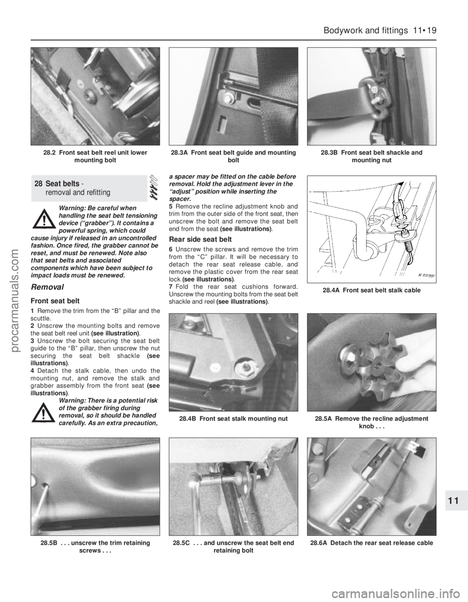
1Remove the trim from the “B” pillar and the
scuttle.
2Unscrew the mounting bolts and remove
the seat belt reel unit (see illustration).
3Unscrew the bolt securing the seat belt
guide to the “B” pillar, then unscrew the nut
securing the seat belt shackle (see
illustrations).
4Detach the stalk cable, then undo the
mounting nut, and remove the stalk and
grabber assembly from the front seat (see
illustrations).
Warning: There is a potential risk
of the grabber firing during
removal, so it should be handled
carefully. As an extra precaution,a spacer may be fitted on the cable before
removal. Hold the adjustment lever in the
“adjust” position while inserting the
spacer.
5Remove the recline adjustment knob and
trim from the outer side of the front seat, then
unscrew the bolt and remove the seat belt
end from the seat (see illustrations).
Rear side seat belt
6Unscrew the screws and remove the trim
from the “C” pillar. It will be necessary to
detach the rear seat release cable, and
remove the plastic cover from the rear seat
lock (see illustrations).
7Fold the rear seat cushions forward.
Unscrew the mounting bolts from the seat belt
shackle and reel (see illustrations).
28 Seat belts -
removal and refitting
Bodywork and fittings 11•19
11
28.5B . . . unscrew the trim retaining
screws . . .28.5C . . . and unscrew the seat belt end
retaining bolt28.6A Detach the rear seat release cable
28.4A Front seat belt stalk cable
28.4B Front seat stalk mounting nut28.5A Remove the recline adjustment
knob . . .
28.2 Front seat belt reel unit lower
mounting bolt28.3A Front seat belt guide and mounting
bolt28.3B Front seat belt shackle and
mounting nut
procarmanuals.com
Page 214 of 279
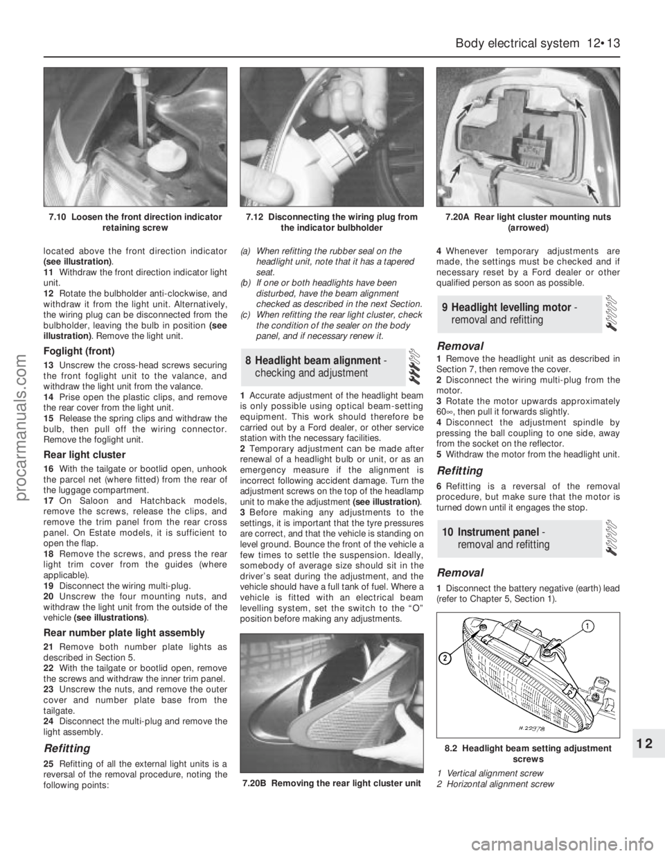
located above the front direction indicator
(see illustration).
11Withdraw the front direction indicator light
unit.
12Rotate the bulbholder anti-clockwise, and
withdraw it from the light unit. Alternatively,
the wiring plug can be disconnected from the
bulbholder, leaving the bulb in position (see
illustration). Remove the light unit.
Foglight (front)
13Unscrew the cross-head screws securing
the front foglight unit to the valance, and
withdraw the light unit from the valance.
14Prise open the plastic clips, and remove
the rear cover from the light unit.
15Release the spring clips and withdraw the
bulb, then pull off the wiring connector.
Remove the foglight unit.
Rear light cluster
16With the tailgate or bootlid open, unhook
the parcel net (where fitted) from the rear of
the luggage compartment.
17On Saloon and Hatchback models,
remove the screws, release the clips, and
remove the trim panel from the rear cross
panel. On Estate models, it is sufficient to
open the flap.
18Remove the screws, and press the rear
light trim cover from the guides (where
applicable).
19Disconnect the wiring multi-plug.
20Unscrew the four mounting nuts, and
withdraw the light unit from the outside of the
vehicle (see illustrations).
Rear number plate light assembly
21Remove both number plate lights as
described in Section 5.
22With the tailgate or bootlid open, remove
the screws and withdraw the inner trim panel.
23Unscrew the nuts, and remove the outer
cover and number plate base from the
tailgate.
24Disconnect the multi-plug and remove the
light assembly.
Refitting
25Refitting of all the external light units is a
reversal of the removal procedure, noting the
following points:(a) When refitting the rubber seal on the
headlight unit, note that it has a tapered
seat.
(b) If one or both headlights have been
disturbed, have the beam alignment
checked as described in the next Section.
(c) When refitting the rear light cluster, check
the condition of the sealer on the body
panel, and if necessary renew it.
1Accurate adjustment of the headlight beam
is only possible using optical beam-setting
equipment. This work should therefore be
carried out by a Ford dealer, or other service
station with the necessary facilities.
2Temporary adjustment can be made after
renewal of a headlight bulb or unit, or as an
emergency measure if the alignment is
incorrect following accident damage. Turn the
adjustment screws on the top of the headlamp
unit to make the adjustment (see illustration).
3Before making any adjustments to the
settings, it is important that the tyre pressures
are correct, and that the vehicle is standing on
level ground. Bounce the front of the vehicle a
few times to settle the suspension. Ideally,
somebody of average size should sit in the
driver’s seat during the adjustment, and the
vehicle should have a full tank of fuel. Where a
vehicle is fitted with an electrical beam
levelling system, set the switch to the “O”
position before making any adjustments.4Whenever temporary adjustments are
made, the settings must be checked and if
necessary reset by a Ford dealer or other
qualified person as soon as possible.
Removal
1Remove the headlight unit as described in
Section 7, then remove the cover.
2Disconnect the wiring multi-plug from the
motor.
3Rotate the motor upwards approximately
60°, then pull it forwards slightly.
4Disconnect the adjustment spindle by
pressing the ball coupling to one side, away
from the socket on the reflector.
5Withdraw the motor from the headlight unit.
Refitting
6Refitting is a reversal of the removal
procedure, but make sure that the motor is
turned down until it engages the stop.
Removal
1Disconnect the battery negative (earth) lead
(refer to Chapter 5, Section 1).
10 Instrument panel -
removal and refitting
9 Headlight levelling motor -
removal and refitting
8 Headlight beam alignment-
checking and adjustment
Body electrical system 12•13
12
7.20B Removing the rear light cluster unit
8.2 Headlight beam setting adjustment
screws
1 Vertical alignment screw
2 Horizontal alignment screw
7.10 Loosen the front direction indicator
retaining screw7.12 Disconnecting the wiring plug from
the indicator bulbholder7.20A Rear light cluster mounting nuts
(arrowed)
procarmanuals.com
Page 216 of 279
6Similarly remove the fuel gauge and
temperature gauge by unscrewing the single
screws.
7Remove all the pin contacts.
8Using a small punch, push in the multi-plug
securing pins, and remove the multi-plugs.
9Carefully lift the printed circuit from the
location dowels on the housing, taking care
not to damage it.
Refitting
10Refitting is a reversal of the removal
procedure.
Removal
1Remove the windscreen wiper arms as
described in Section 15.
2With the bonnet closed, release the grille
panel upper edge from just in front of the
windscreen, by prising off the caps and
unscrewing the upper retaining screws.
3Open the bonnet, and support with the
stay.
4Pull off the sealing strip from the cross
panel at the rear of the engine compartment.
5Unscrew the lower screws, and remove the
grille panel halves from in front of thewindscreen, withdrawing first one side and
then the other.
6Disconnect the battery negative (earth) lead
(refer to Chapter 5, Section 1).
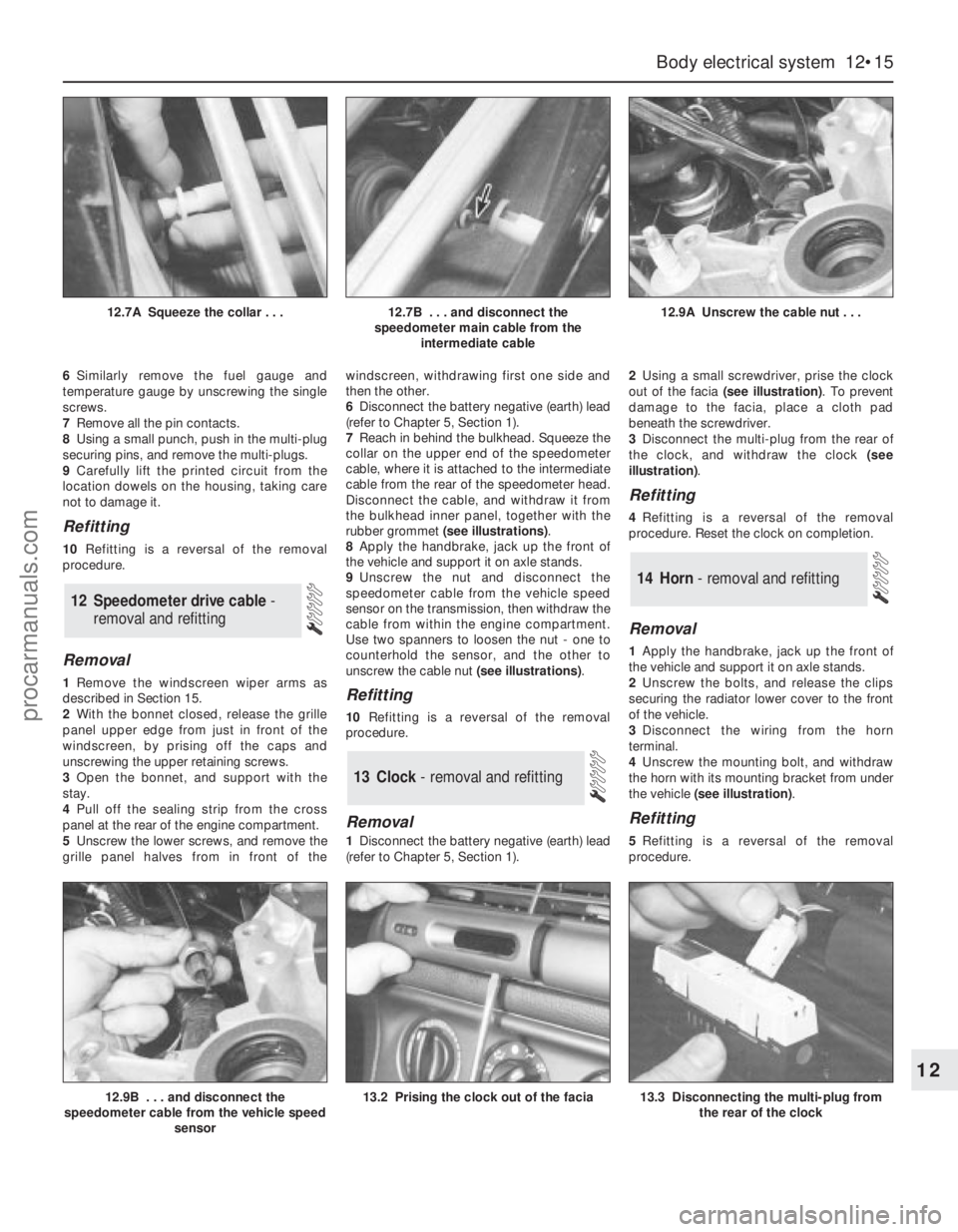
7Reach in behind the bulkhead. Squeeze the
collar on the upper end of the speedometer
cable, where it is attached to the intermediate
cable from the rear of the speedometer head.
Disconnect the cable, and withdraw it from
the bulkhead inner panel, together with the
rubber grommet (see illustrations).
8Apply the handbrake, jack up the front of
the vehicle and support it on axle stands.
9Unscrew the nut and disconnect the
speedometer cable from the vehicle speed
sensor on the transmission, then withdraw the
cable from within the engine compartment.
Use two spanners to loosen the nut - one to
counterhold the sensor, and the other to
unscrew the cable nut (see illustrations).Refitting
10Refitting is a reversal of the removal
procedure.
Removal
1Disconnect the battery negative (earth) lead
(refer to Chapter 5, Section 1).2Using a small screwdriver, prise the clock
out of the facia (see illustration). To prevent
damage to the facia, place a cloth pad
beneath the screwdriver.
3Disconnect the multi-plug from the rear of
the clock, and withdraw the clock (see
illustration).
Refitting
4Refitting is a reversal of the removal
procedure. Reset the clock on completion.
Removal
1Apply the handbrake, jack up the front of
the vehicle and support it on axle stands.
2Unscrew the bolts, and release the clips
securing the radiator lower cover to the front
of the vehicle.
3Disconnect the wiring from the horn
terminal.
4Unscrew the mounting bolt, and withdraw
the horn with its mounting bracket from under
the vehicle (see illustration).
Refitting
5Refitting is a reversal of the removal
procedure.
14 Horn - removal and refitting
13 Clock- removal and refitting
12 Speedometer drive cable -
removal and refitting
Body electrical system 12•15
12
12.9B . . . and disconnect the
speedometer cable from the vehicle speed
sensor13.2 Prising the clock out of the facia13.3 Disconnecting the multi-plug from
the rear of the clock
12.7A Squeeze the collar . . .12.7B . . . and disconnect the
speedometer main cable from the
intermediate cable12.9A Unscrew the cable nut . . .
procarmanuals.com
Page 219 of 279
the specified mileage (or time) since the last
service has been reached.
4To reset the service interval system and
turn off the light, a switch inside the glovebox
must be depressed for a minimum of 4
seconds with the ignition switched on. This
should be carried out by a Ford dealer if the
vehicle is still in the warranty period.
Component renewal
5The following paragraphs describe brief
removal procedures for the auxiliary warning
system components. Disconnect the battery
negative (earth) lead before commencing
work (refer to Chapter 5, Section 1). Refitting
procedures are a reversal of removal.
Display warning bulb
6Remove the control assembly.
7Prise off the cover, and pull out the relevant
bulb and bulbholder.
Low air temperature warning sender
unit
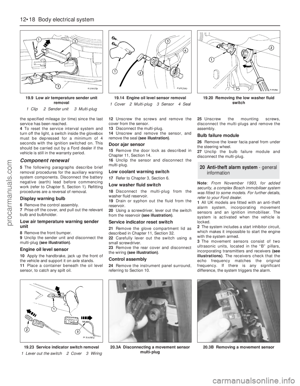
8Remove the front bumper.
9Unclip the sender unit and disconnect the
multi-plug (see illustration).
Engine oil level sensor
10Apply the handbrake, jack up the front of
the vehicle and support it on axle stands.
11Place a container beneath the oil level
sensor, to catch any spilt oil.12Unscrew the screws and remove the
cover from the sensor.
13Disconnect the multi-plug.
14Unscrew and remove the sensor, and
remove the seal (see illustration).
Door ajar sensor
15Remove the door lock as described in
Chapter 11, Section 14.
16Unclip the sensor and disconnect the
multi-plug.
Low coolant warning switch
17Refer to Chapter 3, Section 6.
Low washer fluid switch
18Disconnect the multi-plug from the
washer fluid reservoir.
19Drain or syphon out the fluid from the
reservoir.
20Using a screwdriver, lever out the switch
from the reservoir (see illustration).
Service indicator reset switch
21Remove the glove compartment lid as
described in Chapter 11, Section 32.
22Carefully lever out the switch using a
small screwdriver.
23Remove the rear cover and disconnect
the wiring (see illustration).
Control assembly
24Remove the instrument panel surround,
referring to Section 10.25Unscrew the mounting screws,
disconnect the multi-plugs and remove the
assembly.
Bulb failure module
26Remove the lower facia panel from under
the steering wheel.
27Unclip the bulb failure module and
disconnect the multi-plug.
Note: From November 1993, for added
security, a complex Bosch immobiliser system
was fitted to some models. For further details,
refer to your Ford dealer.
1All UK models are fitted with an anti-theft
alarm system, incorporating movement
sensors and an ignition immobiliser. The
system is activated when the vehicle is
locked.
2The system includes a start inhibitor circuit,
which makes it impossible to start the engine
with the system armed.
3The movement sensors consist of two
ultrasonic units, located in the “B” pillars,
incorporating transmitters and receivers (see
illustrations). The receivers check that the
echo frequency matches the original
frequency. If there is any significant
difference, the system triggers the alarm.
20 Anti-theft alarm system- general
information
12•18 Body electrical system
19.9 Low air temperature sender unit
removal
1 Clip 2 Sender unit 3 Multi-plug19.14 Engine oil level sensor removal
1 Cover 2 Multi-plug 3 Sensor 4 Seal19.20 Removing the low washer fluid
switch
19.23 Service indicator switch removal
1 Lever out the switch 2 Cover 3 Wiring20.3A Disconnecting a movement sensor
multi-plug20.3B Removing a movement sensor
procarmanuals.com
Page 220 of 279
4The system module is located on a bracket
beneath the right-hand side of the facia. The
set and reset switches are located in a
housing by the lock barrel holder in the doors,
tailgate or bootlid.
5To allow temporary opening of the tailgate
or bootlid, an inhibit switch is fitted to the lock
barrel. This suppresses the alarm system until
the tailgate or bootlid is closed again.
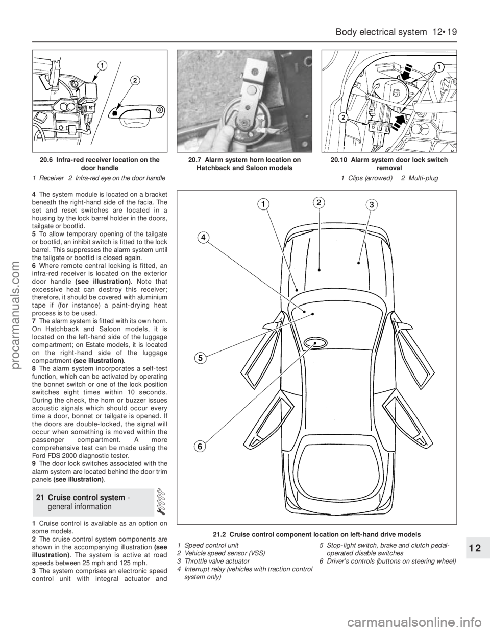
6Where remote central locking is fitted, an
infra-red receiver is located on the exterior
door handle (see illustration). Note that
excessive heat can destroy this receiver;
therefore, it should be covered with aluminium
tape if (for instance) a paint-drying heat
process is to be used.
7The alarm system is fitted with its own horn.
On Hatchback and Saloon models, it is
located on the left-hand side of the luggage
compartment; on Estate models, it is located
on the right-hand side of the luggage
compartment (see illustration).
8The alarm system incorporates a self-test
function, which can be activated by operating
the bonnet switch or one of the lock position
switches eight times within 10 seconds.
During the check, the horn or buzzer issues
acoustic signals which should occur every
time a door, bonnet or tailgate is opened. If
the doors are double-locked, the signal will
occur when something is moved within the
passenger compartment. A more
comprehensive test can be made using the
Ford FDS 2000 diagnostic tester.
9The door lock switches associated with the
alarm system are located behind the door trim
panels (see illustration).
1Cruise control is available as an option on
some models.
2The cruise control system components are
shown in the accompanying illustration (see
illustration). The system is active at road
speeds between 25 mph and 125 mph.
3The system comprises an electronic speed
control unit with integral actuator and
21 Cruise control system -
general information
Body electrical system 12•19
12
21.2 Cruise control component location on left-hand drive models
1 Speed control unit
2 Vehicle speed sensor (VSS)
3 Throttle valve actuator
4 Interrupt relay (vehicles with traction control
system only)5 Stop-light switch, brake and clutch pedal-
operated disable switches
6 Driver’s controls (buttons on steering wheel)
20.6 Infra-red receiver location on the
door handle
1 Receiver 2 Infra-red eye on the door handle20.7 Alarm system horn location on
Hatchback and Saloon models20.10 Alarm system door lock switch
removal
1 Clips (arrowed) 2 Multi-plug
procarmanuals.com