1993 FORD MONDEO service reset
[x] Cancel search: service resetPage 134 of 279

Refitting and adjustment
5With the switch removed, reset it by fully
extending its plunger.
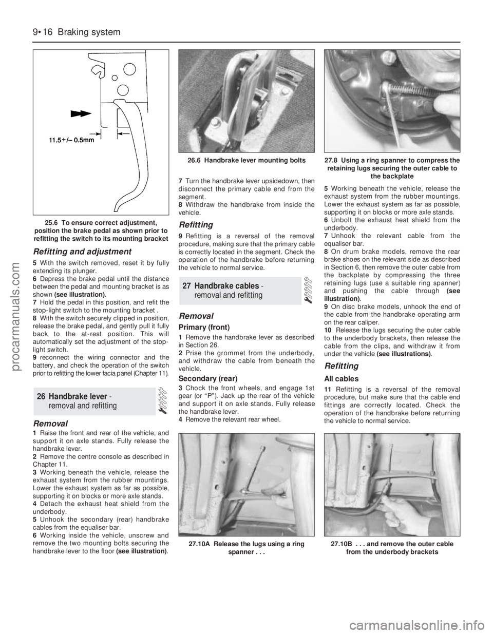
6Depress the brake pedal until the distance
between the pedal and mounting bracket is as
shown (see illustration).
7Hold the pedal in this position, and refit the
stop-light switch to the mounting bracket .
8With the switch securely clipped in position,
release the brake pedal, and gently pull it fully
back to the at-rest position. This will
automatically set the adjustment of the stop-
light switch.
9reconnect the wiring connector and the
battery, and check the operation of the switch
prior to refitting the lower facia panel (Chapter 11).
Removal
1Raise the front and rear of the vehicle, and
support it on axle stands. Fully release the
handbrake lever.
2Remove the centre console as described in
Chapter 11.
3Working beneath the vehicle, release the
exhaust system from the rubber mountings.
Lower the exhaust system as far as possible,
supporting it on blocks or more axle stands.
4Detach the exhaust heat shield from the
underbody.
5Unhook the secondary (rear) handbrake
cables from the equaliser bar.
6Working inside the vehicle, unscrew and
remove the two mounting bolts securing the
handbrake lever to the floor (see illustration).7Turn the handbrake lever upsidedown, then
disconnect the primary cable end from the
segment.
8Withdraw the handbrake from inside the
vehicle.
Refitting
9Refitting is a reversal of the removal
procedure, making sure that the primary cable
is correctly located in the segment. Check the
operation of the handbrake before returning
the vehicle to normal service.
Removal
Primary (front)
1Remove the handbrake lever as described
in Section 26.
2Prise the grommet from the underbody,
and withdraw the cable from beneath the
vehicle.
Secondary (rear)
3Chock the front wheels, and engage 1st
gear (or “P”). Jack up the rear of the vehicle
and support it on axle stands. Fully release
the handbrake lever.
4Remove the relevant rear wheel.5Working beneath the vehicle, release the
exhaust system from the rubber mountings.
Lower the exhaust system as far as possible,
supporting it on blocks or more axle stands.
6Unbolt the exhaust heat shield from the
underbody.
7Unhook the relevant cable from the
equaliser bar.
8On drum brake models, remove the rear
brake shoes on the relevant side as described
in Section 6, then remove the outer cable from
the backplate by compressing the three
retaining lugs (use a suitable ring spanner)
and pushing the cable through (see
illustration).
9On disc brake models, unhook the end of
the cable from the handbrake operating arm
on the rear caliper.
10Release the lugs securing the outer cable
to the underbody brackets, then release the
cable from the clips, and withdraw it from
under the vehicle (see illustrations).
Refitting
All cables
11Refitting is a reversal of the removal
procedure, but make sure that the cable end
fittings are correctly located. Check the
operation of the handbrake before returning
the vehicle to normal service.
27 Handbrake cables -
removal and refitting
26 Handbrake lever -
removal and refitting
9•16 Braking system
25.6 To ensure correct adjustment,
position the brake pedal as shown prior to
refitting the switch to its mounting bracket
26.6 Handbrake lever mounting bolts27.8 Using a ring spanner to compress the
retaining lugs securing the outer cable to
the backplate
27.10A Release the lugs using a ring
spanner . . .27.10B . . . and remove the outer cable
from the underbody brackets
procarmanuals.com
Page 194 of 279

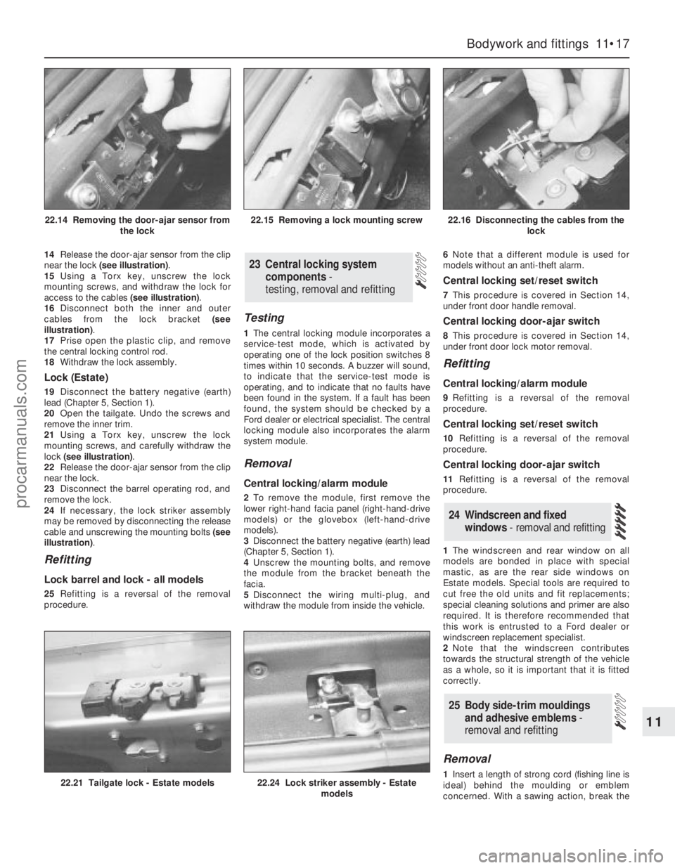
14Release the door-ajar sensor from the clip
near the lock (see illustration).
15Using a Torx key, unscrew the lock
mounting screws, and withdraw the lock for
access to the cables (see illustration).
16Disconnect both the inner and outer
cables from the lock bracket (see
illustration).
17Prise open the plastic clip, and remove
the central locking control rod.
18Withdraw the lock assembly.
Lock (Estate)
19Disconnect the battery negative (earth)
lead (Chapter 5, Section 1).
20Open the tailgate. Undo the screws and
remove the inner trim.
21Using a Torx key, unscrew the lock
mounting screws, and carefully withdraw the
lock (see illustration).
22Release the door-ajar sensor from the clip
near the lock.
23Disconnect the barrel operating rod, and
remove the lock.
24If necessary, the lock striker assembly
may be removed by disconnecting the release
cable and unscrewing the mounting bolts (see
illustration).
Refitting
Lock barrel and lock - all models
25Refitting is a reversal of the removal
procedure.
Testing
1The central locking module incorporates a
service-test mode, which is activated by
operating one of the lock position switches 8
times within 10 seconds. A buzzer will sound,
to indicate that the service-test mode is
operating, and to indicate that no faults have
been found in the system. If a fault has been
found, the system should be checked by a
Ford dealer or electrical specialist. The central
locking module also incorporates the alarm
system module.
Removal
Central locking/alarm module
2To remove the module, first remove the
lower right-hand facia panel (right-hand-drive
models) or the glovebox (left-hand-drive
models).
3Disconnect the battery negative (earth) lead
(Chapter 5, Section 1).
4Unscrew the mounting bolts, and remove
the module from the bracket beneath the
facia.
5Disconnect the wiring multi-plug, and
withdraw the module from inside the vehicle.6Note that a different module is used for
models without an anti-theft alarm.
Central locking set/reset switch
7This procedure is covered in Section 14,
under front door handle removal.
Central locking door-ajar switch
8This procedure is covered in Section 14,
under front door lock motor removal.
Refitting
Central locking/alarm module
9Refitting is a reversal of the removal
procedure.
Central locking set/reset switch
10Refitting is a reversal of the removal
procedure.
Central locking door-ajar switch
11Refitting is a reversal of the removal
procedure.
1The windscreen and rear window on all
models are bonded in place with special
mastic, as are the rear side windows on
Estate models. Special tools are required to
cut free the old units and fit replacements;
special cleaning solutions and primer are also
required. It is therefore recommended that
this work is entrusted to a Ford dealer or
windscreen replacement specialist.
2Note that the windscreen contributes
towards the structural strength of the vehicle
as a whole, so it is important that it is fitted
correctly.
Removal
1Insert a length of strong cord (fishing line is
ideal) behind the moulding or emblem
concerned. With a sawing action, break the
25 Body side-trim mouldings
and adhesive emblems -
removal and refitting
24 Windscreen and fixed
windows - removal and refitting
23 Central locking system
components-
testing, removal and refitting
Bodywork and fittings 11•17
11
22.21 Tailgate lock - Estate models22.24 Lock striker assembly - Estate
models
22.14 Removing the door-ajar sensor from
the lock22.15 Removing a lock mounting screw22.16 Disconnecting the cables from the
lock
procarmanuals.com
Page 214 of 279

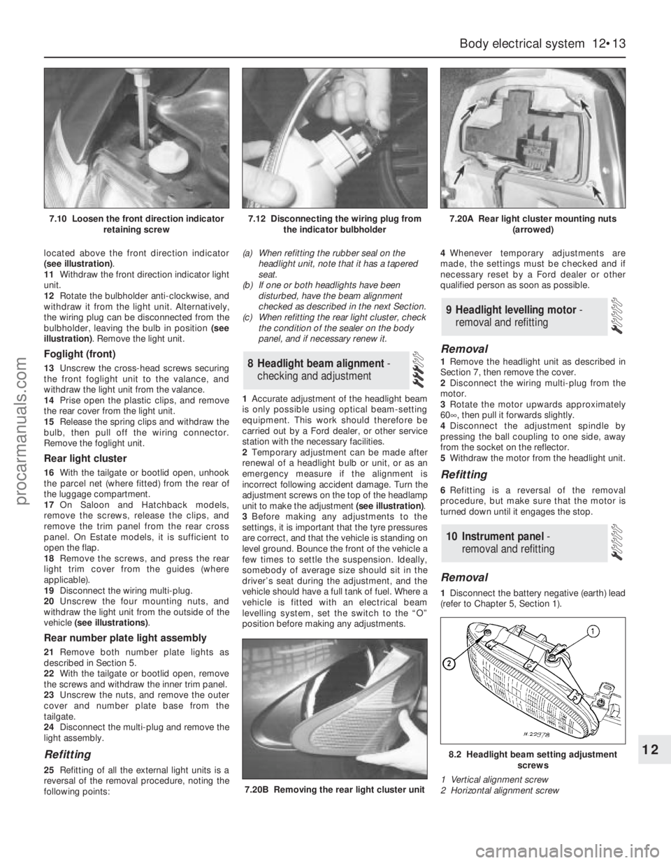
located above the front direction indicator
(see illustration).
11Withdraw the front direction indicator light
unit.
12Rotate the bulbholder anti-clockwise, and
withdraw it from the light unit. Alternatively,
the wiring plug can be disconnected from the
bulbholder, leaving the bulb in position (see
illustration). Remove the light unit.
Foglight (front)
13Unscrew the cross-head screws securing
the front foglight unit to the valance, and
withdraw the light unit from the valance.
14Prise open the plastic clips, and remove
the rear cover from the light unit.
15Release the spring clips and withdraw the
bulb, then pull off the wiring connector.
Remove the foglight unit.
Rear light cluster
16With the tailgate or bootlid open, unhook
the parcel net (where fitted) from the rear of
the luggage compartment.
17On Saloon and Hatchback models,
remove the screws, release the clips, and
remove the trim panel from the rear cross
panel. On Estate models, it is sufficient to
open the flap.
18Remove the screws, and press the rear
light trim cover from the guides (where
applicable).
19Disconnect the wiring multi-plug.
20Unscrew the four mounting nuts, and
withdraw the light unit from the outside of the
vehicle (see illustrations).
Rear number plate light assembly
21Remove both number plate lights as
described in Section 5.
22With the tailgate or bootlid open, remove
the screws and withdraw the inner trim panel.
23Unscrew the nuts, and remove the outer
cover and number plate base from the
tailgate.
24Disconnect the multi-plug and remove the
light assembly.
Refitting
25Refitting of all the external light units is a
reversal of the removal procedure, noting the
following points:(a) When refitting the rubber seal on the
headlight unit, note that it has a tapered
seat.
(b) If one or both headlights have been
disturbed, have the beam alignment
checked as described in the next Section.
(c) When refitting the rear light cluster, check
the condition of the sealer on the body
panel, and if necessary renew it.
1Accurate adjustment of the headlight beam
is only possible using optical beam-setting
equipment. This work should therefore be
carried out by a Ford dealer, or other service
station with the necessary facilities.
2Temporary adjustment can be made after
renewal of a headlight bulb or unit, or as an
emergency measure if the alignment is
incorrect following accident damage. Turn the
adjustment screws on the top of the headlamp
unit to make the adjustment (see illustration).
3Before making any adjustments to the
settings, it is important that the tyre pressures
are correct, and that the vehicle is standing on
level ground. Bounce the front of the vehicle a
few times to settle the suspension. Ideally,
somebody of average size should sit in the
driver’s seat during the adjustment, and the
vehicle should have a full tank of fuel. Where a
vehicle is fitted with an electrical beam
levelling system, set the switch to the “O”
position before making any adjustments.4Whenever temporary adjustments are
made, the settings must be checked and if
necessary reset by a Ford dealer or other
qualified person as soon as possible.
Removal
1Remove the headlight unit as described in
Section 7, then remove the cover.
2Disconnect the wiring multi-plug from the
motor.
3Rotate the motor upwards approximately
60°, then pull it forwards slightly.
4Disconnect the adjustment spindle by
pressing the ball coupling to one side, away
from the socket on the reflector.
5Withdraw the motor from the headlight unit.
Refitting
6Refitting is a reversal of the removal
procedure, but make sure that the motor is
turned down until it engages the stop.
Removal
1Disconnect the battery negative (earth) lead
(refer to Chapter 5, Section 1).
10 Instrument panel -
removal and refitting
9 Headlight levelling motor -
removal and refitting
8 Headlight beam alignment-
checking and adjustment
Body electrical system 12•13
12
7.20B Removing the rear light cluster unit
8.2 Headlight beam setting adjustment
screws
1 Vertical alignment screw
2 Horizontal alignment screw
7.10 Loosen the front direction indicator
retaining screw7.12 Disconnecting the wiring plug from
the indicator bulbholder7.20A Rear light cluster mounting nuts
(arrowed)
procarmanuals.com
Page 219 of 279

the specified mileage (or time) since the last
service has been reached.
4To reset the service interval system and
turn off the light, a switch inside the glovebox
must be depressed for a minimum of 4
seconds with the ignition switched on. This
should be carried out by a Ford dealer if the
vehicle is still in the warranty period.
Component renewal
5The following paragraphs describe brief
removal procedures for the auxiliary warning
system components. Disconnect the battery
negative (earth) lead before commencing
work (refer to Chapter 5, Section 1). Refitting
procedures are a reversal of removal.
Display warning bulb
6Remove the control assembly.
7Prise off the cover, and pull out the relevant
bulb and bulbholder.
Low air temperature warning sender
unit
8Remove the front bumper.
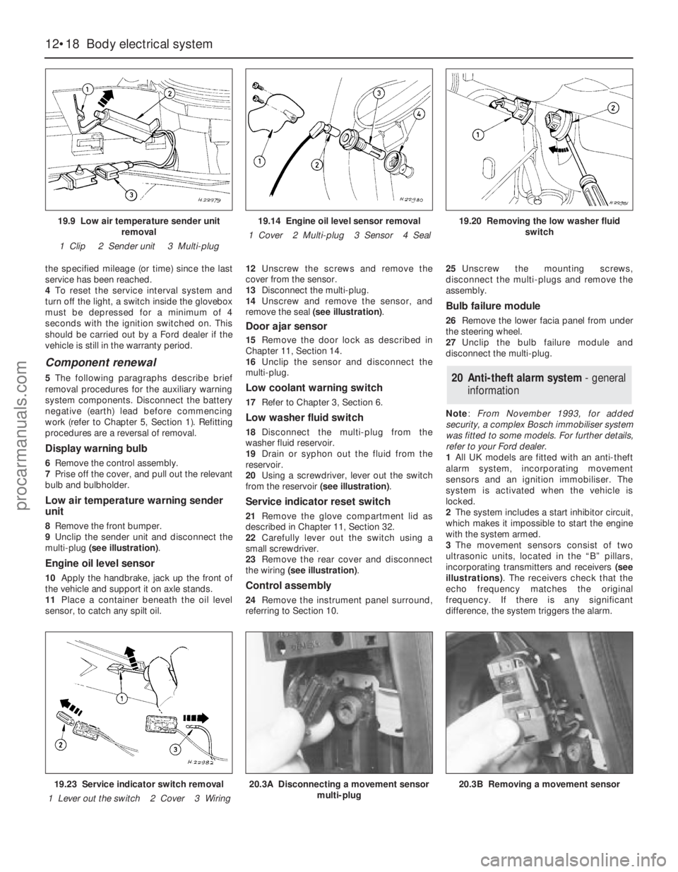
9Unclip the sender unit and disconnect the
multi-plug (see illustration).
Engine oil level sensor
10Apply the handbrake, jack up the front of
the vehicle and support it on axle stands.
11Place a container beneath the oil level
sensor, to catch any spilt oil.12Unscrew the screws and remove the
cover from the sensor.
13Disconnect the multi-plug.
14Unscrew and remove the sensor, and
remove the seal (see illustration).
Door ajar sensor
15Remove the door lock as described in
Chapter 11, Section 14.
16Unclip the sensor and disconnect the
multi-plug.
Low coolant warning switch
17Refer to Chapter 3, Section 6.
Low washer fluid switch
18Disconnect the multi-plug from the
washer fluid reservoir.
19Drain or syphon out the fluid from the
reservoir.
20Using a screwdriver, lever out the switch
from the reservoir (see illustration).
Service indicator reset switch
21Remove the glove compartment lid as
described in Chapter 11, Section 32.
22Carefully lever out the switch using a
small screwdriver.
23Remove the rear cover and disconnect
the wiring (see illustration).
Control assembly
24Remove the instrument panel surround,
referring to Section 10.25Unscrew the mounting screws,
disconnect the multi-plugs and remove the
assembly.
Bulb failure module
26Remove the lower facia panel from under
the steering wheel.
27Unclip the bulb failure module and
disconnect the multi-plug.
Note: From November 1993, for added
security, a complex Bosch immobiliser system
was fitted to some models. For further details,
refer to your Ford dealer.
1All UK models are fitted with an anti-theft
alarm system, incorporating movement
sensors and an ignition immobiliser. The
system is activated when the vehicle is
locked.
2The system includes a start inhibitor circuit,
which makes it impossible to start the engine
with the system armed.
3The movement sensors consist of two
ultrasonic units, located in the “B” pillars,
incorporating transmitters and receivers (see
illustrations). The receivers check that the
echo frequency matches the original
frequency. If there is any significant
difference, the system triggers the alarm.
20 Anti-theft alarm system- general
information
12•18 Body electrical system
19.9 Low air temperature sender unit
removal
1 Clip 2 Sender unit 3 Multi-plug19.14 Engine oil level sensor removal
1 Cover 2 Multi-plug 3 Sensor 4 Seal19.20 Removing the low washer fluid
switch
19.23 Service indicator switch removal
1 Lever out the switch 2 Cover 3 Wiring20.3A Disconnecting a movement sensor
multi-plug20.3B Removing a movement sensor
procarmanuals.com