1993 FORD MONDEO fog light
[x] Cancel search: fog lightPage 8 of 279
Seat belts and seats
Note: The following checks are applicable to
all seat belts, front and rear.
MExamine the webbing of all the belts
(including rear belts if fitted) for cuts, serious
fraying or deterioration. Fasten and unfasten
each belt to check the buckles. If applicable,
check the retracting mechanism. Check the
security of all seat belt mountings accessible
from inside the vehicle.
MThe front seats themselves must be
securely attached and the backrests must
lock in the upright position.
Doors
MBoth front doors must be able to be opened
and closed from outside and inside, and must
latch securely when closed.
Vehicle identification
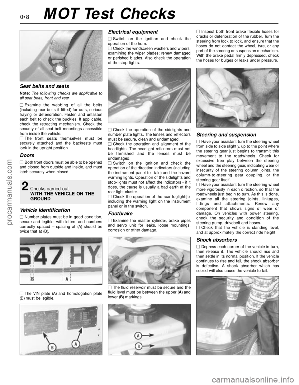
MNumber plates must be in good condition,
secure and legible, with letters and numbers
correctly spaced – spacing at (A) should be
twice that at (B).
MThe VIN plate (A) and homologation plate
(B) must be legible.
Electrical equipment
MSwitch on the ignition and check the
operation of the horn.
MCheck the windscreen washers and wipers,
examining the wiper blades; renew damaged
or perished blades. Also check the operation
of the stop-lights.
MCheck the operation of the sidelights and
number plate lights. The lenses and reflectors
must be secure, clean and undamaged.
MCheck the operation and alignment of the
headlights. The headlight reflectors must not
be tarnished and the lenses must be
undamaged.
MSwitch on the ignition and check the
operation of the direction indicators (including
the instrument panel tell-tale) and the hazard
warning lights. Operation of the sidelights and
stop-lights must not affect the indicators - if it
does, the cause is usually a bad earth at the
rear light cluster.
MCheck the operation of the rear foglight(s),
including the warning light on the instrument
panel or in the switch.
Footbrake
MExamine the master cylinder, brake pipes
and servo unit for leaks, loose mountings,
corrosion or other damage.
MThe fluid reservoir must be secure and the
fluid level must be between the upper (A) and
lower (B) markings.MInspect both front brake flexible hoses for
cracks or deterioration of the rubber. Turn the
steering from lock to lock, and ensure that the
hoses do not contact the wheel, tyre, or any
part of the steering or suspension mechanism.
With the brake pedal firmly depressed, check
the hoses for bulges or leaks under pressure.
Steering and suspension
MHave your assistant turn the steering wheel
from side to side slightly, up to the point where
the steering gear just begins to transmit this
movement to the roadwheels. Check for
excessive free play between the steering
wheel and the steering gear, indicating wear or
insecurity of the steering column joints, the
column-to-steering gear coupling, or the
steering gear itself.
MHave your assistant turn the steering wheel
more vigorously in each direction, so that the
roadwheels just begin to turn. As this is done,
examine all the steering joints, linkages,
fittings and attachments. Renew any
component that shows signs of wear or
damage. On vehicles with power steering,
check the security and condition of the
steering pump, drivebelt and hoses.
MCheck that the vehicle is standing level,
and at approximately the correct ride height.
Shock absorbers
MDepress each corner of the vehicle in turn,
then release it. The vehicle should rise and
then settle in its normal position. If the vehicle
continues to rise and fall, the shock absorber
is defective. A shock absorber which has
seized will also cause the vehicle to fail.
2Checks carried out
WITH THE VEHICLE ON THE
GROUND
0•8MOT Test Checks
procarmanuals.com
Page 181 of 279
Mix up a little filler on a clean piece of card
or board - measure the hardener carefully
(follow the maker’s instructions on the pack),
otherwise the filler will set too rapidly or too
slowly. Using the applicator, apply the filler
paste to the prepared area; draw the
applicator across the surface of the filler to
achieve the correct contour and to level the
surface. As soon as a contour that
approximates to the correct one is achieved,
stop working the paste - if you carry on too
long, the paste will become sticky and begin
to “pick-up” on the applicator. Continue to
add thin layers of filler paste at 20-minute
intervals, until the level of the filler is just
proud of the surrounding bodywork.
Once the filler has hardened, the excess
can be removed using a metal plane or file.
From then on, progressively-finer grades of
abrasive paper should be used, starting with a
40-grade production paper, and finishing with
a 400-grade wet-and-dry paper. Always wrap
the abrasive paper around a flat rubber, cork,
or wooden block - otherwise the surface of
the filler will not be completely flat. During the
smoothing of the filler surface, the wet-and-
dry paper should be periodically rinsed in
water. This will ensure that a very smooth
finish is imparted to the filler at the final stage.
At this stage, the “dent” should be
surrounded by a ring of bare metal, which in
turn should be encircled by the finely
“feathered” edge of the good paintwork.
Rinse the repair area with clean water, until all
of the dust produced by the rubbing-down
operation has gone.
Spray the whole area with a light coat of
primer - this will show up any imperfections in
the surface of the filler. Repair these
imperfections with fresh filler paste or
bodystopper, and once more smooth the
surface with abrasive paper. Repeat this
spray-and-repair procedure until you are
satisfied that the surface of the filler, and the
feathered edge of the paintwork, are perfect.
Clean the repair area with clean water, and
allow to dry fully.
The repair area is now ready for final
spraying. Paint spraying must be carried out
in a warm, dry, windless and dust-free
atmosphere. This condition can be created
artificially if you have access to a large indoor
working area, but if you are forced to work in
the open, you will have to pick your day very
carefully. If you are working indoors, dousing
the floor in the work area with water will help
to settle the dust which would otherwise be in
the atmosphere. If the repair area is confined
to one body panel, mask off the surrounding
panels; this will help to minimise the effects ofa slight mis-match in paint colours. Bodywork
fittings (eg chrome strips, door handles etc)
will also need to be masked off. Use genuine
masking tape, and several thicknesses of
newspaper, for the masking operations.
Before commencing to spray, agitate the
aerosol can thoroughly, then spray a test area
(an old tin, or similar) until the technique is
mastered. Cover the repair area with a thick
coat of primer; the thickness should be built
up using several thin layers of paint, rather
than one thick one. Using 400-grade wet-and-
dry paper, rub down the surface of the primer
until it is really smooth. While doing this, the
work area should be thoroughly doused with
water, and the wet-and-dry paper periodically
rinsed in water. Allow to dry before spraying
on more paint.
Spray on the top coat, again building up the
thickness by using several thin layers of paint.
Start spraying at one edge of the repair area,
and then, using a side-to-side motion, work
until the whole repair area and about 2 inches
of the surrounding original paintwork is
covered. Remove all masking material 10 to
15 minutes after spraying on the final coat of
paint.
Allow the new paint at least two weeks to
harden, then, using a paintwork renovator, or
a very fine cutting paste, blend the edges of
the paint into the existing paintwork. Finally,
apply wax polish.
Plastic components
With the use of more and more plastic body
components by the vehicle manufacturers (eg
bumpers. spoilers, and in some cases major
body panels), rectification of more serious
damage to such items has become a matter
of either entrusting repair work to a specialist
in this field, or renewing complete
components. Repair of such damage by the
DIY owner is not really feasible, owing to the
cost of the equipment and materials required
for effecting such repairs. The basic technique
involves making a groove along the line of the
crack in the plastic, using a rotary burr in a
power drill. The damaged part is then welded
back together, using a hot-air gun to heat up
and fuse a plastic filler rod into the groove.
Any excess plastic is then removed, and the
area rubbed down to a smooth finish. It is
important that a filler rod of the correct plastic
is used, as body components can be made of
a variety of different types (eg polycarbonate,
ABS, polypropylene).
Damage of a less serious nature (abrasions,
minor cracks etc) can be repaired by the DIY
owner using a two-part epoxy filler repair
material. Once mixed in equal proportions,
this is used in similar fashion to the bodywork
filler used on metal panels. The filler is usually
cured in twenty to thirty minutes, ready for
sanding and painting.
If the owner is renewing a complete
component himself, or if he has repaired it
with epoxy filler, he will be left with theproblem of finding a suitable paint for finishing
which is compatible with the type of plastic
used. At one time, the use of a universal paint
was not possible, owing to the complex range
of plastics encountered in body component
applications. Standard paints, generally
speaking, will not bond to plastic or rubber
satisfactorily. However, it is now possible to
obtain a plastic body parts finishing kit which
consists of a pre-primer treatment, a primer
and coloured top coat. Full instructions are
normally supplied with a kit, but basically, the
method of use is to first apply the pre-primer
to the component concerned, and allow it to
dry for up to 30 minutes. Then the primer is
applied, and left to dry for about an hour
before finally applying the special-coloured
top coat. The result is a correctly-coloured
component, where the paint will flex with the
plastic or rubber, a property that standard
paint does not normally posses.
Where serious damage has occurred, or
large areas need renewal due to neglect, it
means that complete new panels will need
welding-in; this is best left to professionals. If
the damage is due to impact, it will also be
necessary to check completely the alignment
of the bodyshell; this can only be carried out
accurately by a Ford dealer, using special jigs.
If the body is left misaligned, it is primarily
dangerous, as the car will not handle properly,
and secondly, uneven stresses will be
imposed on the steering, suspension and
possibly transmission, causing abnormal wear
or complete failure, particularly to items such
as the tyres.
Removal
Front bumper
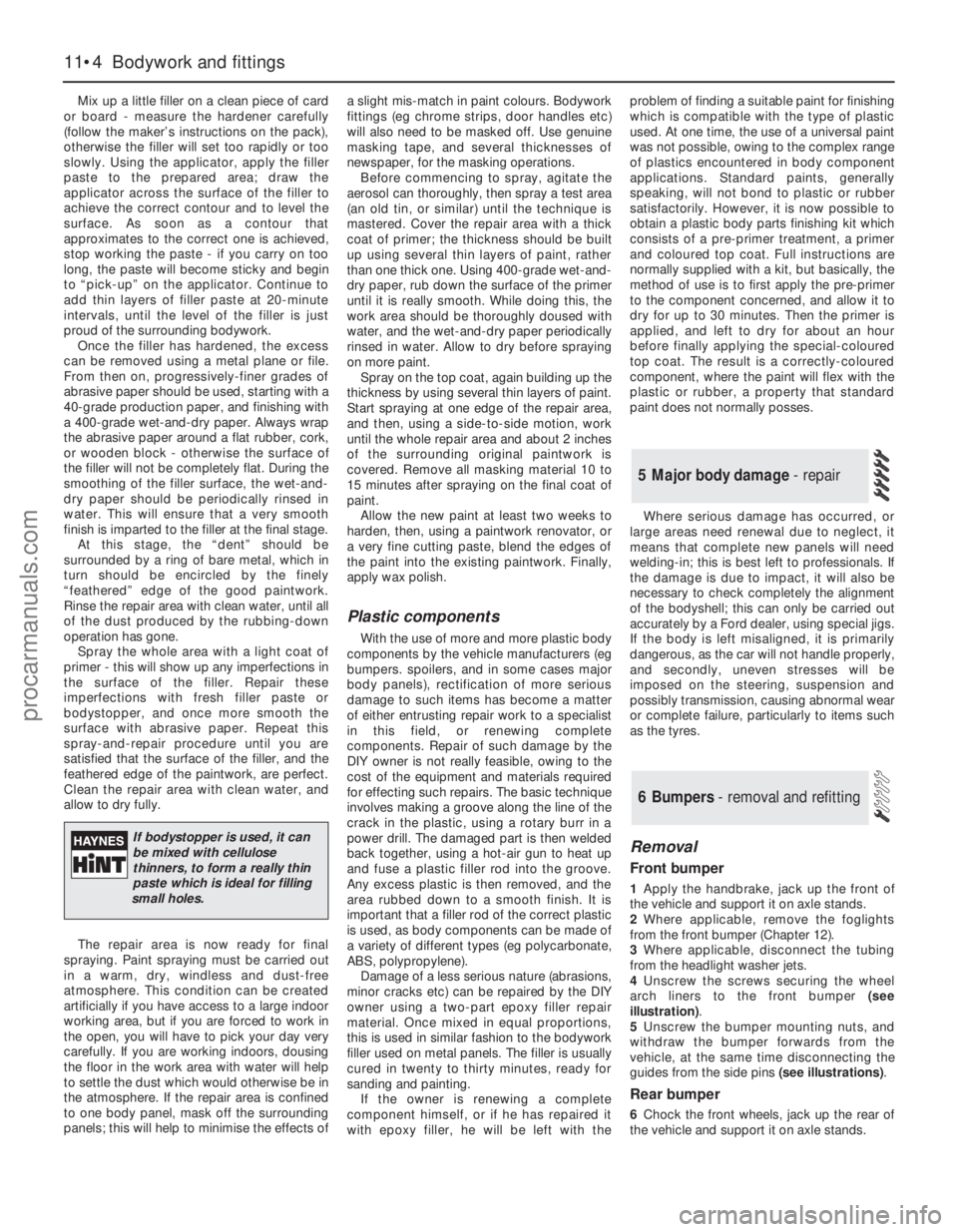
1Apply the handbrake, jack up the front of
the vehicle and support it on axle stands.
2Where applicable, remove the foglights
from the front bumper (Chapter 12).
3Where applicable, disconnect the tubing
from the headlight washer jets.
4Unscrew the screws securing the wheel
arch liners to the front bumper (see
illustration).
5Unscrew the bumper mounting nuts, and
withdraw the bumper forwards from the
vehicle, at the same time disconnecting the
guides from the side pins (see illustrations).
Rear bumper
6Chock the front wheels, jack up the rear of
the vehicle and support it on axle stands.
6 Bumpers - removal and refitting
5 Major body damage - repair
11•4 Bodywork and fittings
If bodystopper is used, it can
be mixed with cellulose
thinners, to form a really thin
paste which is ideal for filling
small holes.
procarmanuals.com
Page 203 of 279
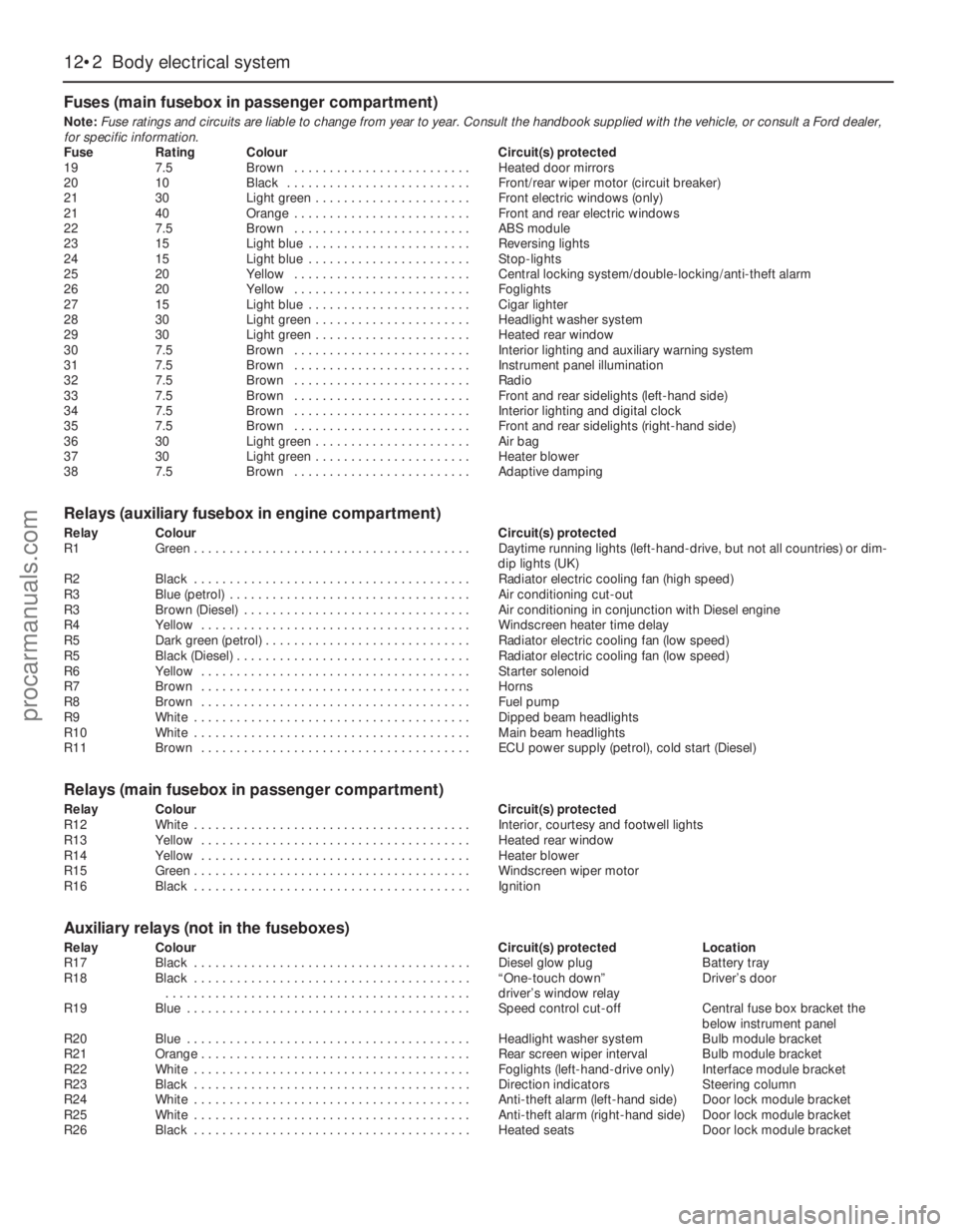
Fuses (main fusebox in passenger compartment)
Note:Fuse ratings and circuits are liable to change from year to year. Consult the handbook supplied with the vehicle, or consult a Ford dealer,
for specific information.
Fuse Rating Colour Circuit(s) protected
19 7.5 Brown . . . . . . . . . . . . . . . . . . . . . . . . . Heated door mirrors
20 10 Black . . . . . . . . . . . . . . . . . . . . . . . . . . Front/rear wiper motor (circuit breaker)
21 30 Light green . . . . . . . . . . . . . . . . . . . . . . Front electric windows (only)
21 40 Orange . . . . . . . . . . . . . . . . . . . . . . . . . Front and rear electric windows
22 7.5 Brown . . . . . . . . . . . . . . . . . . . . . . . . . ABS module
23 15 Light blue . . . . . . . . . . . . . . . . . . . . . . . Reversing lights
24 15 Light blue . . . . . . . . . . . . . . . . . . . . . . . Stop-lights
25 20 Yellow . . . . . . . . . . . . . . . . . . . . . . . . . Central locking system/double-locking/anti-theft alarm
26 20 Yellow . . . . . . . . . . . . . . . . . . . . . . . . . Foglights
27 15 Light blue . . . . . . . . . . . . . . . . . . . . . . . Cigar lighter
28 30 Light green . . . . . . . . . . . . . . . . . . . . . . Headlight washer system
29 30 Light green . . . . . . . . . . . . . . . . . . . . . . Heated rear window
30 7.5 Brown . . . . . . . . . . . . . . . . . . . . . . . . . Interior lighting and auxiliary warning system
31 7.5 Brown . . . . . . . . . . . . . . . . . . . . . . . . . Instrument panel illumination
32 7.5 Brown . . . . . . . . . . . . . . . . . . . . . . . . . Radio
33 7.5 Brown . . . . . . . . . . . . . . . . . . . . . . . . . Front and rear sidelights (left-hand side)
34 7.5 Brown . . . . . . . . . . . . . . . . . . . . . . . . . Interior lighting and digital clock
35 7.5 Brown . . . . . . . . . . . . . . . . . . . . . . . . . Front and rear sidelights (right-hand side)
36 30 Light green . . . . . . . . . . . . . . . . . . . . . . Air bag
37 30 Light green . . . . . . . . . . . . . . . . . . . . . . Heater blower
38 7.5 Brown . . . . . . . . . . . . . . . . . . . . . . . . . Adaptive damping
Relays (auxiliary fusebox in engine compartment)
Relay Colour Circuit(s) protected
R1 Green . . . . . . . . . . . . . . . . . . . . . . . . . . . . . . . . . . . . . . . Daytime running lights (left-hand-drive, but not all countries) or dim-
dip lights (UK)
R2 Black . . . . . . . . . . . . . . . . . . . . . . . . . . . . . . . . . . . . . . . Radiator electric cooling fan (high speed)
R3 Blue (petrol) . . . . . . . . . . . . . . . . . . . . . . . . . . . . . . . . . . Air conditioning cut-out
R3 Brown (Diesel) . . . . . . . . . . . . . . . . . . . . . . . . . . . . . . . . Air conditioning in conjunction with Diesel engine
R4 Yellow . . . . . . . . . . . . . . . . . . . . . . . . . . . . . . . . . . . . . . Windscreen heater time delay
R5 Dark green (petrol) . . . . . . . . . . . . . . . . . . . . . . . . . . . . . Radiator electric cooling fan (low speed)
R5 Black (Diesel) . . . . . . . . . . . . . . . . . . . . . . . . . . . . . . . . . Radiator electric cooling fan (low speed)
R6 Yellow . . . . . . . . . . . . . . . . . . . . . . . . . . . . . . . . . . . . . . Starter solenoid
R7 Brown . . . . . . . . . . . . . . . . . . . . . . . . . . . . . . . . . . . . . . Horns
R8 Brown . . . . . . . . . . . . . . . . . . . . . . . . . . . . . . . . . . . . . . Fuel pump
R9 White . . . . . . . . . . . . . . . . . . . . . . . . . . . . . . . . . . . . . . . Dipped beam headlights
R10 White . . . . . . . . . . . . . . . . . . . . . . . . . . . . . . . . . . . . . . . Main beam headlights
R11 Brown . . . . . . . . . . . . . . . . . . . . . . . . . . . . . . . . . . . . . . ECU power supply (petrol), cold start (Diesel)
Relays (main fusebox in passenger compartment)
Relay Colour Circuit(s) protected
R12 White . . . . . . . . . . . . . . . . . . . . . . . . . . . . . . . . . . . . . . . Interior, courtesy and footwell lights
R13 Yellow . . . . . . . . . . . . . . . . . . . . . . . . . . . . . . . . . . . . . . Heated rear window
R14 Yellow . . . . . . . . . . . . . . . . . . . . . . . . . . . . . . . . . . . . . . Heater blower
R15 Green . . . . . . . . . . . . . . . . . . . . . . . . . . . . . . . . . . . . . . . Windscreen wiper motor
R16 Black . . . . . . . . . . . . . . . . . . . . . . . . . . . . . . . . . . . . . . . Ignition
Auxiliary relays (not in the fuseboxes)
Relay Colour Circuit(s) protected Location
R17 Black . . . . . . . . . . . . . . . . . . . . . . . . . . . . . . . . . . . . . . . Diesel glow plug Battery tray
R18 Black . . . . . . . . . . . . . . . . . . . . . . . . . . . . . . . . . . . . . . . “One-touch down” Driver’s door
. . . . . . . . . . . . . . . . . . . . . . . . . . . . . . . . . . . . . . . . . . . driver’s window relay
R19 Blue . . . . . . . . . . . . . . . . . . . . . . . . . . . . . . . . . . . . . . . . Speed control cut-off Central fuse box bracket the
below instrument panel
R20 Blue . . . . . . . . . . . . . . . . . . . . . . . . . . . . . . . . . . . . . . . . Headlight washer system Bulb module bracket
R21 Orange . . . . . . . . . . . . . . . . . . . . . . . . . . . . . . . . . . . . . . Rear screen wiper interval Bulb module bracket
R22 White . . . . . . . . . . . . . . . . . . . . . . . . . . . . . . . . . . . . . . . Foglights (left-hand-drive only) Interface module bracket
R23 Black . . . . . . . . . . . . . . . . . . . . . . . . . . . . . . . . . . . . . . . Direction indicators Steering column
R24 White . . . . . . . . . . . . . . . . . . . . . . . . . . . . . . . . . . . . . . . Anti-theft alarm (left-hand side) Door lock module bracket
R25 White . . . . . . . . . . . . . . . . . . . . . . . . . . . . . . . . . . . . . . . Anti-theft alarm (right-hand side) Door lock module bracket
R26 Black . . . . . . . . . . . . . . . . . . . . . . . . . . . . . . . . . . . . . . . Heated seats Door lock module bracket
12•2 Body electrical system
procarmanuals.com
Page 204 of 279
BulbsWattage Type
Headlight main beam . . . . . . . . . . . . . . . . . . . . . . . . . . . . . . . . . . . . . . . 55 Halogen
Headlight dipped beam . . . . . . . . . . . . . . . . . . . . . . . . . . . . . . . . . . . . . . 55 Halogen
Foglights . . . . . . . . . . . . . . . . . . . . . . . . . . . . . . . . . . . . . . . . . . . . . . . . . 55 Halogen
Sidelights . . . . . . . . . . . . . . . . . . . . . . . . . . . . . . . . . . . . . . . . . . . . . . . . . 5 Wedge
Direction indicator lights . . . . . . . . . . . . . . . . . . . . . . . . . . . . . . . . . . . . . 21 Bayonet
Side repeater lights . . . . . . . . . . . . . . . . . . . . . . . . . . . . . . . . . . . . . . . . . 5 Wedge
Stop-lights . . . . . . . . . . . . . . . . . . . . . . . . . . . . . . . . . . . . . . . . . . . . . . . . 21 Bayonet
Reversing lights . . . . . . . . . . . . . . . . . . . . . . . . . . . . . . . . . . . . . . . . . . . . 21 Bayonet
Rear fog/tail lights (Saloon and Estate) . . . . . . . . . . . . . . . . . . . . . . . . . . 21/4 Bayonet
Rear tail light (Saloon and Hatchback) . . . . . . . . . . . . . . . . . . . . . . . . . . 5 Bayonet
Number plate lights . . . . . . . . . . . . . . . . . . . . . . . . . . . . . . . . . . . . . . . . . 5 Festoon
Engine compartment . . . . . . . . . . . . . . . . . . . . . . . . . . . . . . . . . . . . . . . . 10 Wedge
Interior lights . . . . . . . . . . . . . . . . . . . . . . . . . . . . . . . . . . . . . . . . . . . . . . 10 Festoon
Reading light . . . . . . . . . . . . . . . . . . . . . . . . . . . . . . . . . . . . . . . . . . . . . . 5 Wedge
Torque wrench settingsNm lbf ft
Windscreen wiper motor bolts:
Into old motor (see text) . . . . . . . . . . . . . . . . . . . . . . . . . . . . . . . . . . . 8 6
Into new motor (see text) . . . . . . . . . . . . . . . . . . . . . . . . . . . . . . . . . . . 12 9
Body electrical system 12•3
12
Warning: Before carrying out any
work on the electrical system,
read through the precautions
given in “Safety first!” at the beginning of
this manual.The electrical system is of 12-volt negative
earth type. Power for the lights and all
electrical accessories is supplied by a
lead/acid battery which is charged by the
alternator.
This Chapter covers repair and service
procedures for the various electrical
components not associated with the engine.
Information on the battery, ignition system,alternator, and starter motor can be found in
Chapter 5.
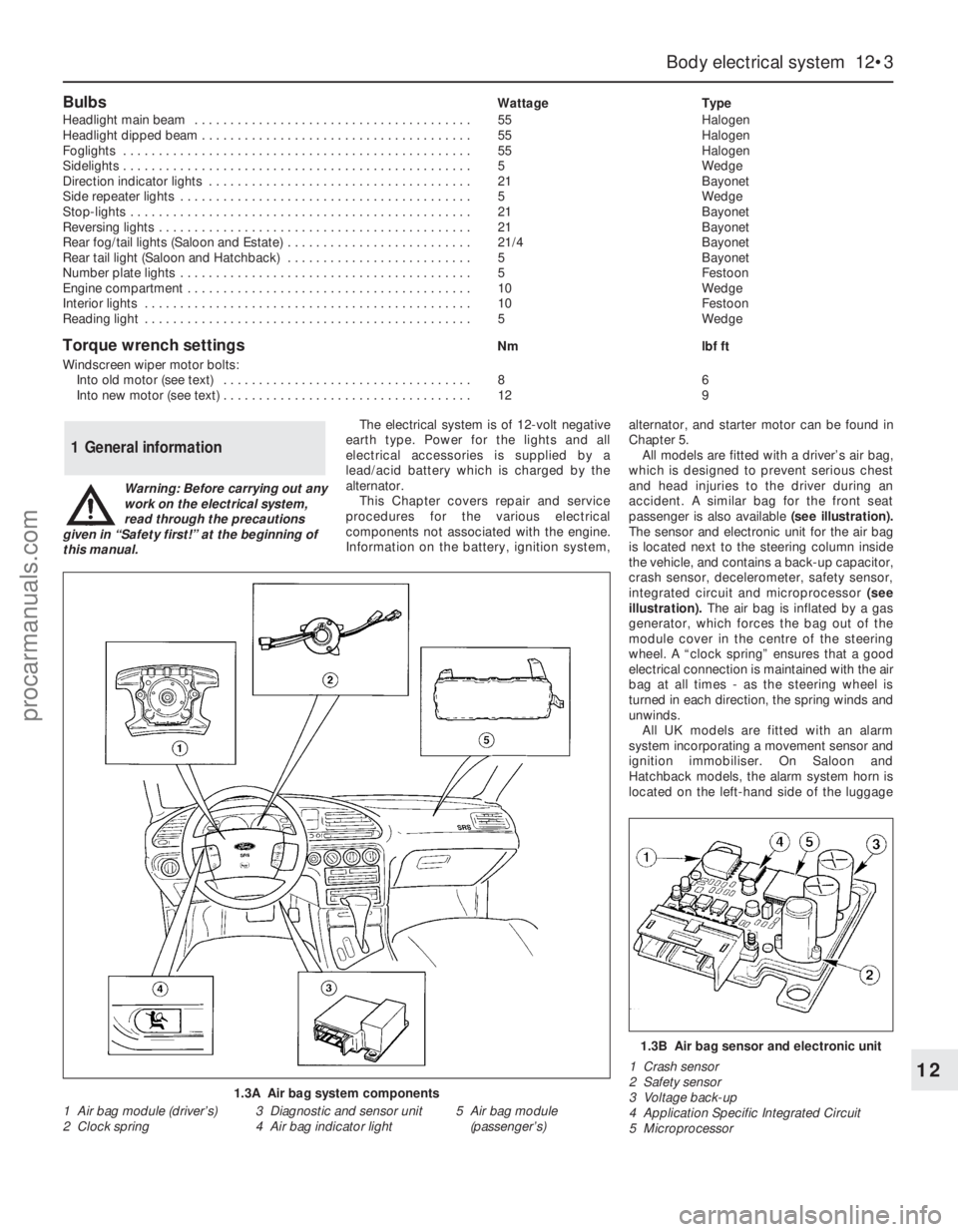
All models are fitted with a driver’s air bag,
which is designed to prevent serious chest
and head injuries to the driver during an
accident. A similar bag for the front seat
passenger is also available (see illustration).
The sensor and electronic unit for the air bag
is located next to the steering column inside
the vehicle, and contains a back-up capacitor,
crash sensor, decelerometer, safety sensor,
integrated circuit and microprocessor (see
illustration). The air bag is inflated by a gas
generator, which forces the bag out of the
module cover in the centre of the steering
wheel. A “clock spring” ensures that a good
electrical connection is maintained with the air
bag at all times - as the steering wheel is
turned in each direction, the spring winds and
unwinds.
All UK models are fitted with an alarm
system incorporating a movement sensor and
ignition immobiliser. On Saloon and
Hatchback models, the alarm system horn is
located on the left-hand side of the luggage
1 General information
1.3A Air bag system components
1 Air bag module (driver’s)
2 Clock spring3 Diagnostic and sensor unit
4 Air bag indicator light5 Air bag module
(passenger’s)
1.3B Air bag sensor and electronic unit
1 Crash sensor
2 Safety sensor
3 Voltage back-up
4 Application Specific Integrated Circuit
5 Microprocessor
procarmanuals.com
Page 208 of 279
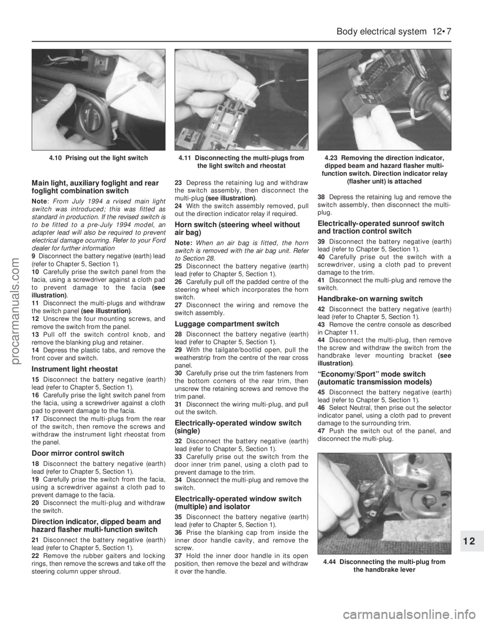
Main light, auxiliary foglight and rear
foglight combination switch
Note:From July 1994 a rvised main light
switch was introduced; this was fitted as
standard in production. If the revised switch is
to be fitted to a pre-July 1994 model, an
adapter lead will also be required to prevent
electrical damage ocurring. Refer to your Ford
dealer for further information
9Disconnect the battery negative (earth) lead
(refer to Chapter 5, Section 1).
10Carefully prise the switch panel from the
facia, using a screwdriver against a cloth pad
to prevent damage to the facia (see
illustration).
11Disconnect the multi-plugs and withdraw
the switch panel (see illustration).
12Unscrew the four mounting screws, and
remove the switch from the panel.
13Pull off the switch control knob, and
remove the blanking plug and retainer.
14Depress the plastic tabs, and remove the
front cover and switch.
Instrument light rheostat
15Disconnect the battery negative (earth)
lead (refer to Chapter 5, Section 1).
16Carefully prise the light switch panel from
the facia, using a screwdriver against a cloth
pad to prevent damage to the facia.
17Disconnect the multi-plugs from the rear
of the switch, then remove the screws and
withdraw the instrument light rheostat from
the panel.
Door mirror control switch
18Disconnect the battery negative (earth)
lead (refer to Chapter 5, Section 1).
19Carefully prise the switch from the facia,
using a screwdriver against a cloth pad to
prevent damage to the facia.
20Disconnect the multi-plug and withdraw
the switch.
Direction indicator, dipped beam and
hazard flasher multi-function switch
21Disconnect the battery negative (earth)
lead (refer to Chapter 5, Section 1).
22Remove the rubber gaiters and locking
rings, then remove the screws and take off the
steering column upper shroud.23Depress the retaining lug and withdraw
the switch assembly, then disconnect the
multi-plug (see illustration).
24With the switch assembly removed, pull
out the direction indicator relay if required.
Horn switch (steering wheel without
air bag)
Note:When an air bag is fitted, the horn
switch is removed with the air bag unit. Refer
to Section 28.
25Disconnect the battery negative (earth)
lead (refer to Chapter 5, Section 1).
26Carefully pull off the padded centre of the
steering wheel which incorporates the horn
switch.
27Disconnect the wiring and remove the
switch assembly.
Luggage compartment switch
28Disconnect the battery negative (earth)
lead (refer to Chapter 5, Section 1).
29With the tailgate/bootlid open, pull the
weatherstrip from the centre of the rear cross
panel.
30Carefully prise out the trim fasteners from
the bottom corners of the rear trim, then
unscrew the retaining screws and remove the
trim panel.
31Disconnect the wiring multi-plug, and pull
out the switch.
Electrically-operated window switch
(single)
32Disconnect the battery negative (earth)
lead (refer to Chapter 5, Section 1).
33Carefully prise out the switch from the
door inner trim panel, using a cloth pad to
prevent damage to the trim.
34Disconnect the multi-plug and remove the
switch.
Electrically-operated window switch
(multiple) and isolator
35Disconnect the battery negative (earth)
lead (refer to Chapter 5, Section 1).
36Prise the blanking cap from inside the
inner door handle cavity, and remove the
screw.
37Hold the inner door handle in its open
position, then remove the bezel and withdraw
it over the handle.38Depress the retaining lug and remove the
switch assembly, then disconnect the multi-
plug.
Electrically-operated sunroof switch
and traction control switch
39Disconnect the battery negative (earth)
lead (refer to Chapter 5, Section 1).
40Carefully prise out the switch with a
screwdriver, using a cloth pad to prevent
damage to the trim.
41Disconnect the multi-plug and remove the
switch.
Handbrake-on warning switch
42Disconnect the battery negative (earth)
lead (refer to Chapter 5, Section 1).
43Remove the centre console as described
in Chapter 11.
44Disconnect the multi-plug, then remove
the screw and withdraw the switch from the
handbrake lever mounting bracket (see
illustration).
“Economy/Sport” mode switch
(automatic transmission models)
45Disconnect the battery negative (earth)
lead (refer to Chapter 5, Section 1).
46Select Neutral, then prise out the selector
indicator panel, using a cloth pad to prevent
damage to the surrounding trim.
47Push the switch out of the panel, and
disconnect the multi-plug.
Body electrical system 12•7
12
4.44 Disconnecting the multi-plug from
the handbrake lever
4.10 Prising out the light switch4.11 Disconnecting the multi-plugs from
the light switch and rheostat4.23 Removing the direction indicator,
dipped beam and hazard flasher multi-
function switch. Direction indicator relay
(flasher unit) is attached
procarmanuals.com
Page 209 of 279
Heated windscreen switch and heated
rear window switch
48Disconnect the battery negative (earth)
lead (refer to Chapter 5, Section 1).
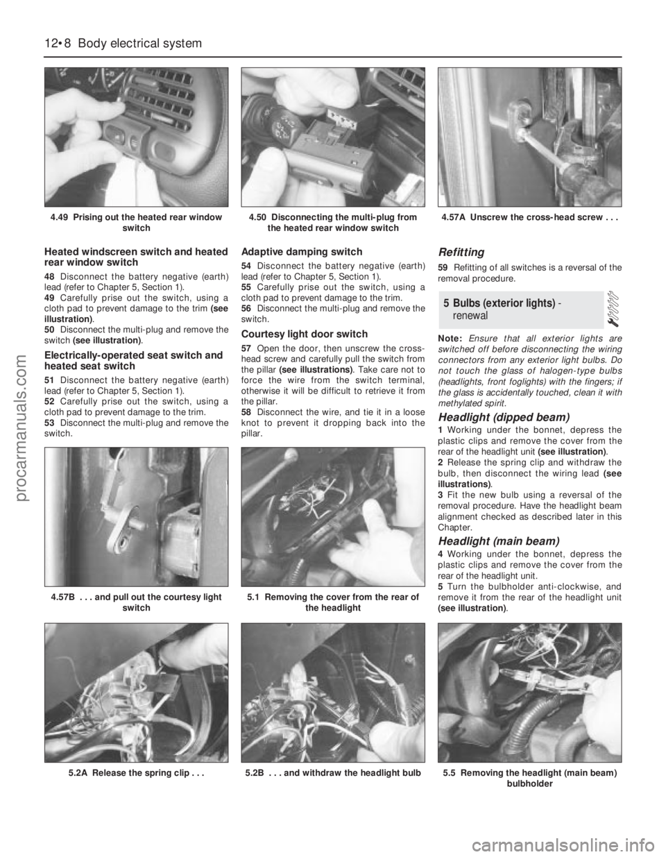
49Carefully prise out the switch, using a
cloth pad to prevent damage to the trim (see
illustration).
50Disconnect the multi-plug and remove the
switch (see illustration).
Electrically-operated seat switch and
heated seat switch
51Disconnect the battery negative (earth)
lead (refer to Chapter 5, Section 1).
52Carefully prise out the switch, using a
cloth pad to prevent damage to the trim.
53Disconnect the multi-plug and remove the
switch.
Adaptive damping switch
54Disconnect the battery negative (earth)
lead (refer to Chapter 5, Section 1).
55Carefully prise out the switch, using a
cloth pad to prevent damage to the trim.
56Disconnect the multi-plug and remove the
switch.
Courtesy light door switch
57Open the door, then unscrew the cross-
head screw and carefully pull the switch from
the pillar (see illustrations). Take care not to
force the wire from the switch terminal,
otherwise it will be difficult to retrieve it from
the pillar.
58Disconnect the wire, and tie it in a loose
knot to prevent it dropping back into the
pillar.
Refitting
59Refitting of all switches is a reversal of the
removal procedure.
Note:Ensure that all exterior lights are
switched off before disconnecting the wiring
connectors from any exterior light bulbs. Do
not touch the glass of halogen-type bulbs
(headlights, front foglights) with the fingers; if
the glass is accidentally touched, clean it with
methylated spirit.
Headlight (dipped beam)
1Working under the bonnet, depress the
plastic clips and remove the cover from the
rear of the headlight unit (see illustration).
2Release the spring clip and withdraw the
bulb, then disconnect the wiring lead (see
illustrations).
3Fit the new bulb using a reversal of the
removal procedure. Have the headlight beam
alignment checked as described later in this
Chapter.
Headlight (main beam)
4Working under the bonnet, depress the
plastic clips and remove the cover from the
rear of the headlight unit.
5Turn the bulbholder anti-clockwise, and
remove it from the rear of the headlight unit
(see illustration).
5 Bulbs (exterior lights) -
renewal
12•8 Body electrical system
4.49 Prising out the heated rear window
switch4.50 Disconnecting the multi-plug from
the heated rear window switch4.57A Unscrew the cross-head screw . . .
5.2A Release the spring clip . . .5.2B . . . and withdraw the headlight bulb
4.57B . . . and pull out the courtesy light
switch5.1 Removing the cover from the rear of
the headlight
5.5 Removing the headlight (main beam)
bulbholder
procarmanuals.com
Page 210 of 279
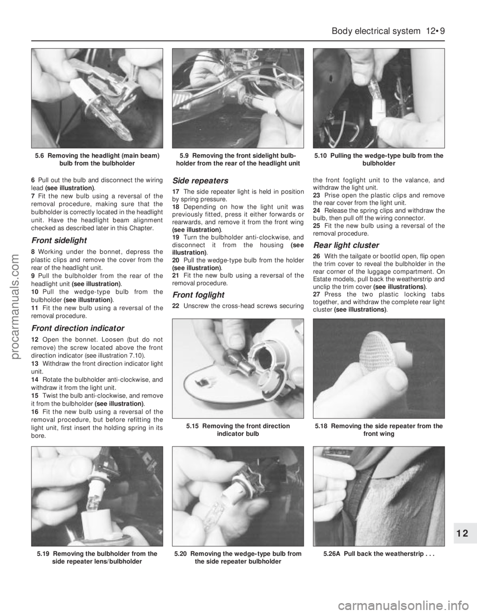
6Pull out the bulb and disconnect the wiring
lead (see illustration).
7Fit the new bulb using a reversal of the
removal procedure, making sure that the
bulbholder is correctly located in the headlight
unit. Have the headlight beam alignment
checked as described later in this Chapter.
Front sidelight
8Working under the bonnet, depress the
plastic clips and remove the cover from the
rear of the headlight unit.
9Pull the bulbholder from the rear of the
headlight unit (see illustration).
10Pull the wedge-type bulb from the
bulbholder (see illustration).
11Fit the new bulb using a reversal of the
removal procedure.
Front direction indicator
12Open the bonnet. Loosen (but do not
remove) the screw located above the front
direction indicator (see illustration 7.10).
13Withdraw the front direction indicator light
unit.
14Rotate the bulbholder anti-clockwise, and
withdraw it from the light unit.
15Twist the bulb anti-clockwise, and remove
it from the bulbholder (see illustration).
16Fit the new bulb using a reversal of the
removal procedure, but before refitting the
light unit, first insert the holding spring in its
bore.
Side repeaters
17The side repeater light is held in position
by spring pressure.
18Depending on how the light unit was
previously fitted, press it either forwards or
rearwards, and remove it from the front wing
(see illustration).
19Turn the bulbholder anti-clockwise, and
disconnect it from the housing (see
illustration).
20Pull the wedge-type bulb from the holder
(see illustration).
21Fit the new bulb using a reversal of the
removal procedure.
Front foglight
22Unscrew the cross-head screws securingthe front foglight unit to the valance, and
withdraw the light unit.
23Prise open the plastic clips and remove
the rear cover from the light unit.
24Release the spring clips and withdraw the
bulb, then pull off the wiring connector.
25Fit the new bulb using a reversal of the
removal procedure.
Rear light cluster
26With the tailgate or bootlid open, flip open
the trim cover to reveal the bulbholder in the
rear corner of the luggage compartment. On
Estate models, pull back the weatherstrip and
unclip the trim cover (see illustrations).
27Press the two plastic locking tabs
together, and withdraw the complete rear light
cluster (see illustrations).
Body electrical system 12•9
12
5.19 Removing the bulbholder from the
side repeater lens/bulbholder5.20 Removing the wedge-type bulb from
the side repeater bulbholder5.26A Pull back the weatherstrip . . .
5.15 Removing the front direction
indicator bulb5.18 Removing the side repeater from the
front wing
5.6 Removing the headlight (main beam)
bulb from the bulbholder5.9 Removing the front sidelight bulb-
holder from the rear of the headlight unit5.10 Pulling the wedge-type bulb from the
bulbholder
procarmanuals.com
Page 212 of 279
Engine compartment light
1With the bonnet open, pull the wedge-type
bulb from the bulbholder.
2Fit the new bulb using a reversal of the
removal procedure.
Interior lights
3Switch off the interior light by locating the
switch in its middle position.
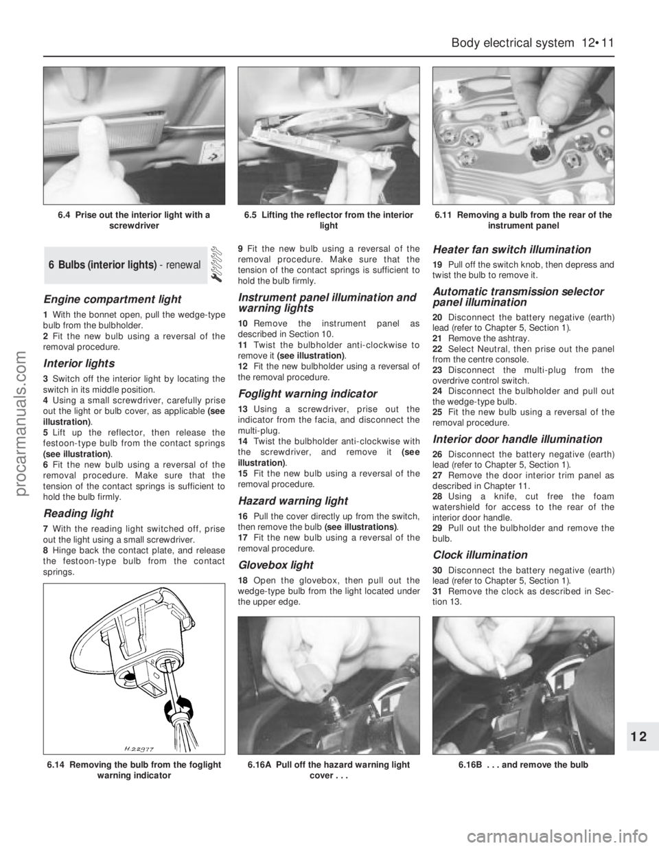
4Using a small screwdriver, carefully prise
out the light or bulb cover, as applicable (see
illustration).
5Lift up the reflector, then release the
festoon-type bulb from the contact springs
(see illustration).
6Fit the new bulb using a reversal of the
removal procedure. Make sure that the
tension of the contact springs is sufficient to
hold the bulb firmly.
Reading light
7With the reading light switched off, prise
out the light using a small screwdriver.
8Hinge back the contact plate, and release
the festoon-type bulb from the contact
springs.9Fit the new bulb using a reversal of the
removal procedure. Make sure that the
tension of the contact springs is sufficient to
hold the bulb firmly.
Instrument panel illumination and
warning lights
10Remove the instrument panel as
described in Section 10.
11Twist the bulbholder anti-clockwise to
remove it (see illustration).
12Fit the new bulbholder using a reversal of
the removal procedure.
Foglight warning indicator
13Using a screwdriver, prise out the
indicator from the facia, and disconnect the
multi-plug.
14Twist the bulbholder anti-clockwise with
the screwdriver, and remove it (see
illustration).
15Fit the new bulb using a reversal of the
removal procedure.
Hazard warning light
16Pull the cover directly up from the switch,
then remove the bulb (see illustrations).
17Fit the new bulb using a reversal of the
removal procedure.
Glovebox light
18Open the glovebox, then pull out the
wedge-type bulb from the light located under
the upper edge.
Heater fan switch illumination
19Pull off the switch knob, then depress and
twist the bulb to remove it.
Automatic transmission selector
panel illumination
20Disconnect the battery negative (earth)
lead (refer to Chapter 5, Section 1).
21Remove the ashtray.
22Select Neutral, then prise out the panel
from the centre console.
23Disconnect the multi-plug from the
overdrive control switch.
24Disconnect the bulbholder and pull out
the wedge-type bulb.
25Fit the new bulb using a reversal of the
removal procedure.
Interior door handle illumination
26Disconnect the battery negative (earth)
lead (refer to Chapter 5, Section 1).
27Remove the door interior trim panel as
described in Chapter 11.
28Using a knife, cut free the foam
watershield for access to the rear of the
interior door handle.
29Pull out the bulbholder and remove the
bulb.
Clock illumination
30Disconnect the battery negative (earth)
lead (refer to Chapter 5, Section 1).
31Remove the clock as described in Sec-
tion 13.
6 Bulbs (interior lights) - renewal
Body electrical system 12•11
12
6.14 Removing the bulb from the foglight
warning indicator6.16A Pull off the hazard warning light
cover . . .6.16B . . . and remove the bulb
6.4 Prise out the interior light with a
screwdriver6.5 Lifting the reflector from the interior
light6.11 Removing a bulb from the rear of the
instrument panel
procarmanuals.com