1993 FORD MONDEO wheel size
[x] Cancel search: wheel sizePage 10 of 279
0•10
MExamine the handbrake mechanism,
checking for frayed or broken cables,
excessive corrosion, or wear or insecurity of
the linkage. Check that the mechanism works
on each relevant wheel, and releases fully,
without binding.
MIt is not possible to test brake efficiency
without special equipment, but a road test
can be carried out later to check that the
vehicle pulls up in a straight line.
Fuel and exhaust systems
MInspect the fuel tank (including the filler
cap), fuel pipes, hoses and unions. All
components must be secure and free from
leaks.
MExamine the exhaust system over its entire
length, checking for any damaged, broken or
missing mountings, security of the retaining
clamps and rust or corrosion.
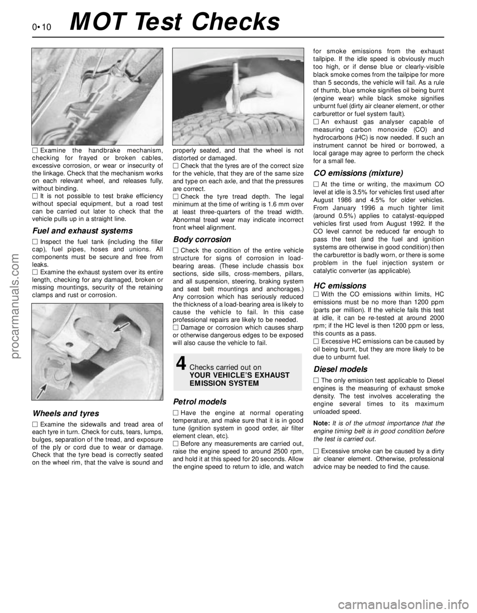
Wheels and tyres
MExamine the sidewalls and tread area of
each tyre in turn. Check for cuts, tears, lumps,
bulges, separation of the tread, and exposure
of the ply or cord due to wear or damage.
Check that the tyre bead is correctly seated
on the wheel rim, that the valve is sound andproperly seated, and that the wheel is not
distorted or damaged.
MCheck that the tyres are of the correct size
for the vehicle, that they are of the same size
and type on each axle, and that the pressures
are correct.
MCheck the tyre tread depth. The legal
minimum at the time of writing is 1.6 mm over
at least three-quarters of the tread width.
Abnormal tread wear may indicate incorrect
front wheel alignment.
Body corrosion
MCheck the condition of the entire vehicle
structure for signs of corrosion in load-
bearing areas. (These include chassis box
sections, side sills, cross-members, pillars,
and all suspension, steering, braking system
and seat belt mountings and anchorages.)
Any corrosion which has seriously reduced
the thickness of a load-bearing area is likely to
cause the vehicle to fail. In this case
professional repairs are likely to be needed.
MDamage or corrosion which causes sharp
or otherwise dangerous edges to be exposed
will also cause the vehicle to fail.
Petrol models
MHave the engine at normal operating
temperature, and make sure that it is in good
tune (ignition system in good order, air filter
element clean, etc).
MBefore any measurements are carried out,
raise the engine speed to around 2500 rpm,
and hold it at this speed for 20 seconds. Allow
the engine speed to return to idle, and watchfor smoke emissions from the exhaust
tailpipe. If the idle speed is obviously much
too high, or if dense blue or clearly-visible
black smoke comes from the tailpipe for more
than 5 seconds, the vehicle will fail. As a rule
of thumb, blue smoke signifies oil being burnt
(engine wear) while black smoke signifies
unburnt fuel (dirty air cleaner element, or other
carburettor or fuel system fault).
MAn exhaust gas analyser capable of
measuring carbon monoxide (CO) and
hydrocarbons (HC) is now needed. If such an
instrument cannot be hired or borrowed, a
local garage may agree to perform the check
for a small fee.
CO emissions (mixture)
MAt the time or writing, the maximum CO
level at idle is 3.5% for vehicles first used after
August 1986 and 4.5% for older vehicles.
From January 1996 a much tighter limit
(around 0.5%) applies to catalyst-equipped
vehicles first used from August 1992. If the
CO level cannot be reduced far enough to
pass the test (and the fuel and ignition
systems are otherwise in good condition) then
the carburettor is badly worn, or there is some
problem in the fuel injection system or
catalytic converter (as applicable).
HC emissionsMWith the CO emissions within limits, HC
emissions must be no more than 1200 ppm
(parts per million). If the vehicle fails this test
at idle, it can be re-tested at around 2000
rpm; if the HC level is then 1200 ppm or less,
this counts as a pass.
MExcessive HC emissions can be caused by
oil being burnt, but they are more likely to be
due to unburnt fuel.
Diesel models
MThe only emission test applicable to Diesel
engines is the measuring of exhaust smoke
density. The test involves accelerating the
engine several times to its maximum
unloaded speed.
Note: It is of the utmost importance that the
engine timing belt is in good condition before
the test is carried out.
M
Excessive smoke can be caused by a dirty
air cleaner element. Otherwise, professional
advice may be needed to find the cause.
4Checks carried out on
YOUR VEHICLE’S EXHAUST
EMISSION SYSTEM
MOT Test Checks
procarmanuals.com
Page 30 of 279
comb” or compressed air to clean the
condenser.
Warning: Wear eye protection
when using compressed air!
(d) Check that the drain tube from the front
of the evaporator is clear - note that it is
normal to have clear fluid (water) dripping
from this while the system is in operation,
to the extent that quite a large puddle can
be left under the vehicle when it is parked.
2It’s a good idea to operate the system forabout 30 minutes at least once a month,
particularly during the winter. Long term
non-use can cause hardening, and
subsequent failure, of the seals.
3Because of the complexity of the air
conditioning system and the special
equipment necessary to service it, in-depth
fault diagnosis and repairs are not included in
this manual. For more complete information
on the air conditioning system, refer to the
Haynes Automotive Heating and Air
Conditioning Manual.
4The most common cause of poor cooling is
simply a low system refrigerant charge. If a
noticeable drop in cool air output occurs, the
following quick check will help you determine
if the refrigerant level is low.
5Warm the engine up to normal operating
temperature.
6Place the air conditioning temperature
selector at the coldest setting, and put the
blower at the highest setting. Open the doors
- to make sure the air conditioning system
doesn’t cycle off as soon as it cools the
passenger compartment.
7With the compressor engaged - the clutch
will make an audible click, and the centre of
the clutch will rotate - feel the inlet and outlet
pipes at the compressor. One side should be
cold, and one hot. If there’s no perceptible
difference between the two pipes, there’s
something wrong with the compressor or the
system. It might be a low charge - it might be
something else. Take the vehicle to a dealer
service department or an automotive air
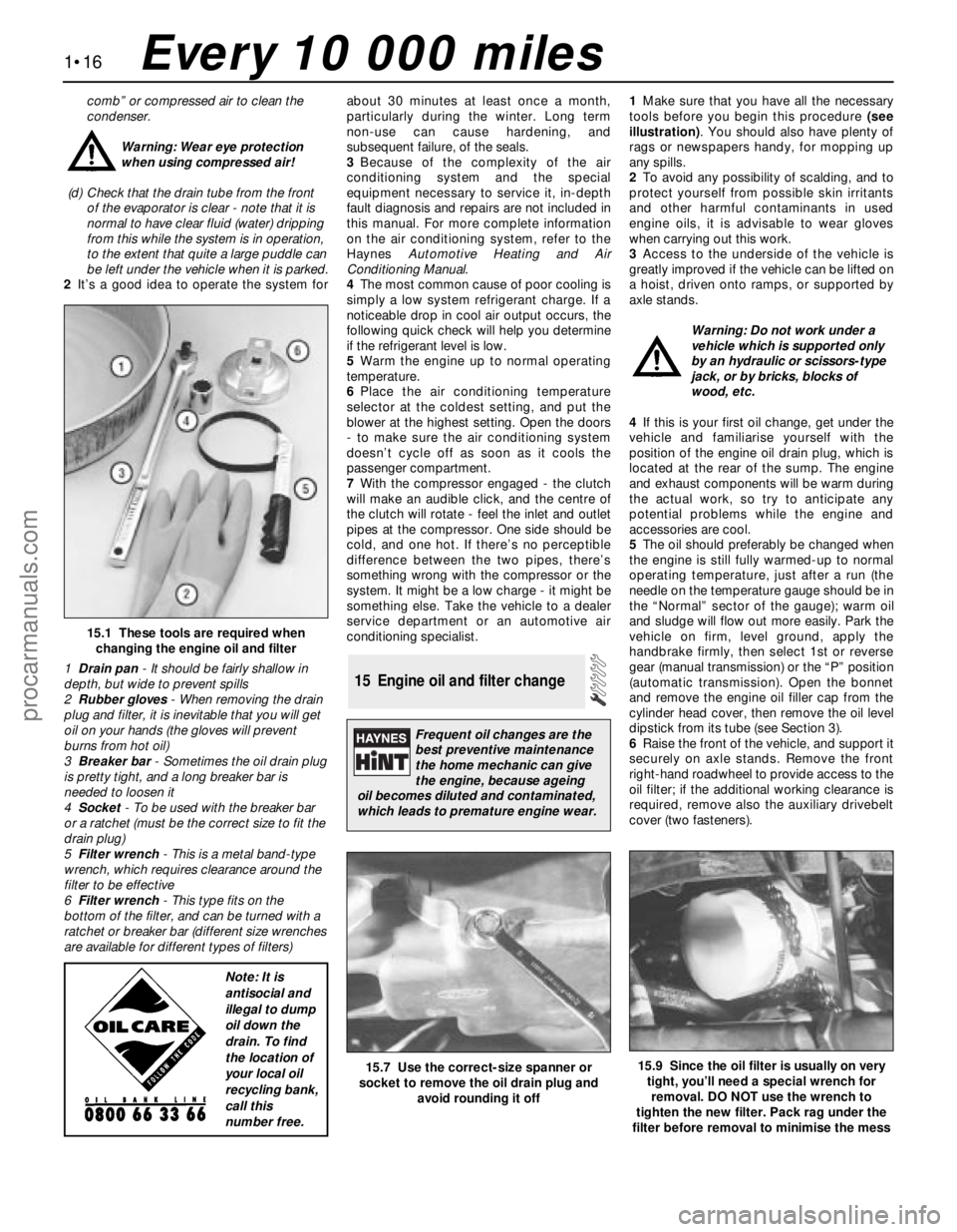
conditioning specialist.1Make sure that you have all the necessary
tools before you begin this procedure (see
illustration). You should also have plenty of
rags or newspapers handy, for mopping up
any spills.
2To avoid any possibility of scalding, and to
protect yourself from possible skin irritants
and other harmful contaminants in used
engine oils, it is advisable to wear gloves
when carrying out this work.
3Access to the underside of the vehicle is
greatly improved if the vehicle can be lifted on
a hoist, driven onto ramps, or supported by
axle stands.
Warning: Do not work under a
vehicle which is supported only
by an hydraulic or scissors-type
jack, or by bricks, blocks of
wood, etc.
4If this is your first oil change, get under the
vehicle and familiarise yourself with the
position of the engine oil drain plug, which is
located at the rear of the sump. The engine
and exhaust components will be warm during
the actual work, so try to anticipate any
potential problems while the engine and
accessories are cool.
5The oil should preferably be changed when
the engine is still fully warmed-up to normal
operating temperature, just after a run (the
needle on the temperature gauge should be in
the “Normal” sector of the gauge); warm oil
and sludge will flow out more easily. Park the
vehicle on firm, level ground, apply the
handbrake firmly, then select 1st or reverse
gear (manual transmission) or the “P” position
(automatic transmission). Open the bonnet
and remove the engine oil filler cap from the
cylinder head cover, then remove the oil level
dipstick from its tube (see Section 3).
6Raise the front of the vehicle, and support it
securely on axle stands. Remove the front
right-hand roadwheel to provide access to the
oil filter; if the additional working clearance is
required, remove also the auxiliary drivebelt
cover (two fasteners).
15 Engine oil and filter change
1•16
15.1 These tools are required when
changing the engine oil and filter
1Drain pan- It should be fairly shallow in
depth, but wide to prevent spills
2Rubber gloves- When removing the drain
plug and filter, it is inevitable that you will get
oil on your hands (the gloves will prevent
burns from hot oil)
3Breaker bar- Sometimes the oil drain plug
is pretty tight, and a long breaker bar is
needed to loosen it
4Socket- To be used with the breaker bar
or a ratchet (must be the correct size to fit the
drain plug)
5Filter wrench- This is a metal band-type
wrench, which requires clearance around the
filter to be effective
6Filter wrench- This type fits on the
bottom of the filter, and can be turned with a
ratchet or breaker bar (different size wrenches
are available for different types of filters)
15.7 Use the correct-size spanner or
socket to remove the oil drain plug and
avoid rounding it off15.9 Since the oil filter is usually on very
tight, you’ll need a special wrench for
removal. DO NOT use the wrench to
tighten the new filter. Pack rag under the
filter before removal to minimise the mess
Every 10 000 miles
Frequent oil changes are the
best preventive maintenance
the home mechanic can give
the engine, because ageing
oil becomes diluted and contaminated,
which leads to premature engine wear.
Note: It is
antisocial and
illegal to dump
oil down the
drain. To find
the location of
your local oil
recycling bank,
call this
number free.
procarmanuals.com
Page 63 of 279
3Clean the seal housing and crankshaft,
polishing off any burrs or raised edges, which
may have caused the seal to fail in the first
place.
4Refit the oil pump (see Section 16). Grease
the lips and periphery of the new seal, to ease
installation.
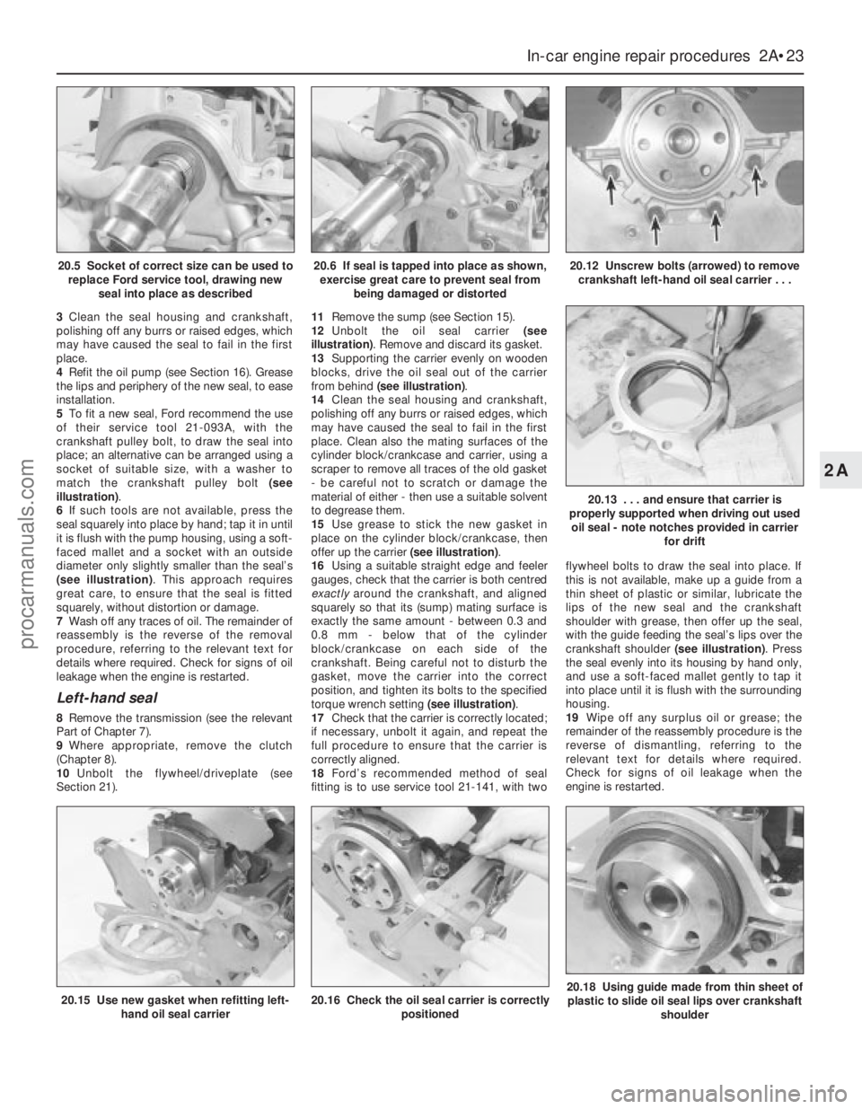
5To fit a new seal, Ford recommend the use
of their service tool 21-093A, with the
crankshaft pulley bolt, to draw the seal into
place; an alternative can be arranged using a
socket of suitable size, with a washer to
match the crankshaft pulley bolt (see
illustration).
6If such tools are not available, press the
seal squarely into place by hand; tap it in until
it is flush with the pump housing, using a soft-
faced mallet and a socket with an outside
diameter only slightly smaller than the seal’s
(see illustration). This approach requires
great care, to ensure that the seal is fitted
squarely, without distortion or damage.
7Wash off any traces of oil. The remainder of
reassembly is the reverse of the removal
procedure, referring to the relevant text for
details where required. Check for signs of oil
leakage when the engine is restarted.
Left-hand seal
8Remove the transmission (see the relevant
Part of Chapter 7).
9Where appropriate, remove the clutch
(Chapter 8).
10Unbolt the flywheel/driveplate (see
Section 21).11Remove the sump (see Section 15).
12Unbolt the oil seal carrier (see
illustration). Remove and discard its gasket.
13Supporting the carrier evenly on wooden
blocks, drive the oil seal out of the carrier
from behind (see illustration).
14Clean the seal housing and crankshaft,
polishing off any burrs or raised edges, which
may have caused the seal to fail in the first
place. Clean also the mating surfaces of the
cylinder block/crankcase and carrier, using a
scraper to remove all traces of the old gasket
- be careful not to scratch or damage the
material of either - then use a suitable solvent
to degrease them.
15Use grease to stick the new gasket in
place on the cylinder block/crankcase, then
offer up the carrier (see illustration).
16Using a suitable straight edge and feeler
gauges, check that the carrier is both centred
exactlyaround the crankshaft, and aligned
squarely so that its (sump) mating surface is
exactly the same amount - between 0.3 and
0.8 mm - below that of the cylinder
block/crankcase on each side of the
crankshaft. Being careful not to disturb the
gasket, move the carrier into the correct
position, and tighten its bolts to the specified
torque wrench setting (see illustration).
17Check that the carrier is correctly located;
if necessary, unbolt it again, and repeat the
full procedure to ensure that the carrier is
correctly aligned.
18Ford’s recommended method of seal
fitting is to use service tool 21-141, with twoflywheel bolts to draw the seal into place. If
this is not available, make up a guide from a
thin sheet of plastic or similar, lubricate the
lips of the new seal and the crankshaft
shoulder with grease, then offer up the seal,
with the guide feeding the seal’s lips over the
crankshaft shoulder (see illustration). Press
the seal evenly into its housing by hand only,
and use a soft-faced mallet gently to tap it
into place until it is flush with the surrounding
housing.
19Wipe off any surplus oil or grease; the
remainder of the reassembly procedure is the
reverse of dismantling, referring to the
relevant text for details where required.
Check for signs of oil leakage when the
engine is restarted.
In-car engine repair procedures 2A•23
2A
20.15 Use new gasket when refitting left-
hand oil seal carrier20.16 Check the oil seal carrier is correctly
positioned20.18 Using guide made from thin sheet of
plastic to slide oil seal lips over crankshaft
shoulder
20.5 Socket of correct size can be used to
replace Ford service tool, drawing new
seal into place as described20.6 If seal is tapped into place as shown,
exercise great care to prevent seal from
being damaged or distorted20.12 Unscrew bolts (arrowed) to remove
crankshaft left-hand oil seal carrier . . .
20.13 . . . and ensure that carrier is
properly supported when driving out used
oil seal - note notches provided in carrier
for drift
procarmanuals.com
Page 72 of 279
inner wing panel, release the engine
wiring loom and refit the power steering
fluid reservoir.
(g) Secure the engine wiring loom neatly to
the engine/transmission so that it cannot
be damaged as the unit is removed from
the vehicle.
14Unbolt both parts of the exhaust manifold
heat shield; unclip the coolant hose to allow
the upper part to be withdrawn.
15Remove the auxiliary drivebelt (see
Chapter 1).
16Unbolt the power steering pump (see
Chapter 10); secure it as far as possible
(without disconnecting the system’s hoses)
clear of the engine/transmission.
17Raise the vehicle and support it securely
on axle stands, then remove the front
roadwheels. Drain the cooling system and (if
the engine is to be dismantled) drain the
engine oil and remove the oil filter (see
Chapter 1). Also drain the transmission as
described in the relevant Part of Chapter 7.
18Withdraw the lower part of the exhaust
manifold heat shield.
19Unscrew the nuts to disconnect the
exhaust system front downpipe from the
manifold, then unhook all the system’s rubber
mountings and withdraw the complete
exhaust system from under the vehicle (see
Chapter 4 for details).
20Where the vehicle is fitted with manual
transmission, mark their positions, then
disconnect the gearchange linkage and
transmission support rods from the rear of the
transmission. Unscrew the retaining nuts, and
withdraw the gear linkage heat shield from the
underbody. Unbolt the rear end of the linkage
from the underbody, swivel the linkage around
to the rear, and tie it to the underbody (see
Chapter 7, Part A, for details).
21Disconnect both anti-roll bar links from
their respective suspension strut - note the
flexible brake hose bracket attached to each
link stud - and both track rod ends from their
steering knuckles. Unfasten the clamp bolt
securing each front suspension lower arm
balljoint to its steering knuckle (see Chap-
ter 10 for details). Check that both balljoints
can be released from the knuckle assemblies
when required, but leave them in place for thetime being, secured by the clamp bolts if
necessary.
22Where the vehicle is fitted with air
conditioning, unbolt the accumulator/
dehydrator from the subframe; secure it as far
as possible (without disconnecting the
system’s hoses) clear of the engine/
transmission.
Warning: Do not disconnect the
refrigerant hoses.
23Unbolt the steering gear from the
subframe; if the bolts are not accessible from
above, a Ford service tool will be required to
reach them from underneath the vehicle (see
Chapter 10 for details).
24Unscrew the two bolts securing the power
steering system pipes to the right-hand side
of the subframe.
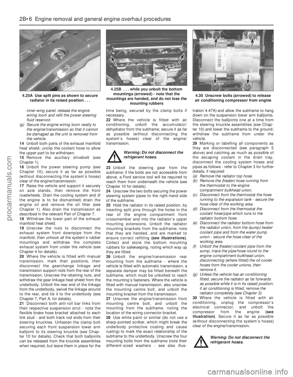
25Hold the radiator in its raised position, by
inserting split pins through the holes in the
rear of the engine compartment front
crossmember and into the radiator’s upper
mounting extensions. Unbolt the radiator
mounting brackets from the subframe; note
that they are handed, and are marked to
ensure correct refitting (see illustrations).
Collect and store the bottom mounting
rubbers for safekeeping, noting which way up
they are fitted.
26Unbolt the engine/transmission rear
mounting from the subframe - where the
vehicle is fitted with automatic transmission, a
separate damper may be fitted beneath the
subframe, which must be unbolted to reach
the mounting’s fasteners. Where the vehicle is
fitted with manual transmission, also unscrew
the mounting centre bolt, and unbolt the
mounting bracket from the transmission.
27Unscrew the engine/transmission front
mounting centre bolt, and unbolt the
mounting from the subframe, noting the
location of the wiring connector bracket.
28Use white paint or similar (do not use a
sharp-pointed scriber, which might break the
underbody protective coating and cause
rusting) to mark the exact relationship of the
subframe to the underbody. Unscrew the four
mounting bolts from the subframe (note their
different-sized washers - see also illus-tration 4.47A) and allow the subframe to hang
down on the suspension lower arm balljoints.
Disconnect the balljoints one at a time from
the steering knuckle assemblies (see Chap-
ter 10) and lower the subframe to the ground;
withdraw the subframe from under the
vehicle.
29Marking or labelling all components as
they are disconnected (see paragraph 5
above) and catching as much as possible of
the escaping coolant in the drain tray,
disconnect the cooling system hoses and
pipes as follows - refer to Chapter 3 for further
details, if required:
(a) Remove the radiator top hose.
(b) Remove the (heater) hose running from
the thermostat to the engine
compartment bulkhead union.
(c) Disconnect from the thermostat the hose
running to the expansion tank - secure the
hose clear of the working area.
(d) Disconnect from the thermostat the
coolant hose/pipe which runs to the
radiator bottom hose.
(e) Disconnect the radiator bottom hose from
the radiator union, from the (sump) heater
coolant pipe and from the water pump
union - secure the hose clear of the
working area.
(f) Unbolt the (heater) coolant pipe from the
sump, trace the pipe/hose round to the
engine compartment bulkhead union,
disconnecting (where fitted) the oil cooler
hoses from the cooler unions, then
remove it.
(g) Unless the vehicle has air conditioning
fitted, secure the radiator as far forwards
as possible while it is in its raised position;
if air conditioning is fitted, remove the
radiator completely (see Chapter 3).
30Where the vehicle is fitted with air
conditioning, unplug the compressor’s
electrical connector, and unbolt the
compressor from the engine (see
illustration). Secure it as far as possible
(without disconnecting the system’s hoses)
clear of the engine/transmission.
Warning: Do not disconnect the
refrigerant hoses.
2B•6 Engine removal and general engine overhaul procedures
4.25A Use split pins as shown to secure
radiator in its raised position . . .
4.25B . . . while you unbolt the bottom
mountings (arrowed) - note that the
mountings are handed, and do not lose the
mounting rubbers
4.30 Unscrew bolts (arrowed) to release
air conditioning compressor from engine
procarmanuals.com
Page 80 of 279
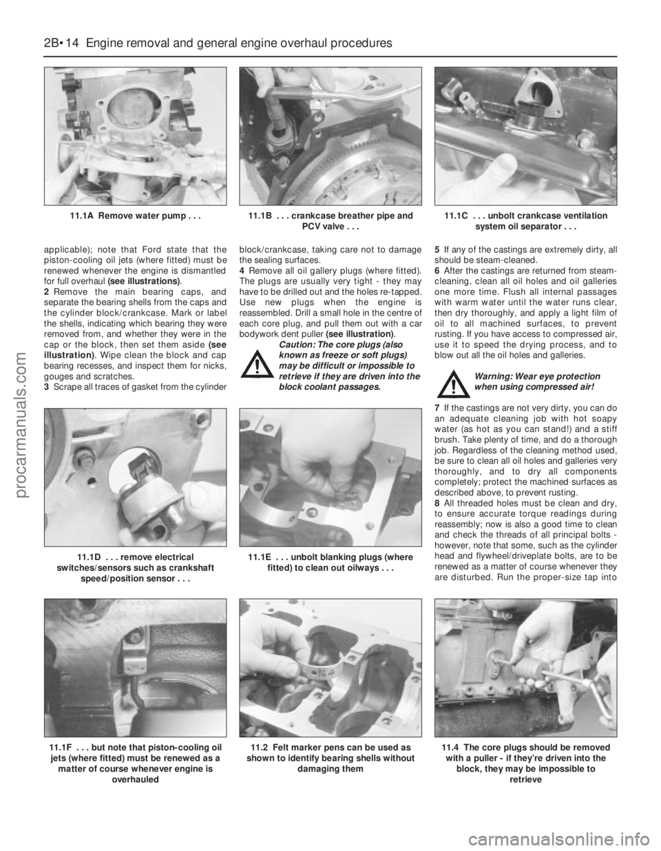
applicable); note that Ford state that the
piston-cooling oil jets (where fitted) must be
renewed whenever the engine is dismantled
for full overhaul (see illustrations).
2Remove the main bearing caps, and
separate the bearing shells from the caps and
the cylinder block/crankcase. Mark or label
the shells, indicating which bearing they were
removed from, and whether they were in the
cap or the block, then set them aside (see
illustration). Wipe clean the block and cap
bearing recesses, and inspect them for nicks,
gouges and scratches.
3Scrape all traces of gasket from the cylinderblock/crankcase, taking care not to damage
the sealing surfaces.
4Remove all oil gallery plugs (where fitted).
The plugs are usually very tight - they may
have to be drilled out and the holes re-tapped.
Use new plugs when the engine is
reassembled. Drill a small hole in the centre of
each core plug, and pull them out with a car
bodywork dent puller (see illustration).
Caution: The core plugs (also
known as freeze or soft plugs)
may be difficult or impossible to
retrieve if they are driven into the
block coolant passages.5If any of the castings are extremely dirty, all
should be steam-cleaned.
6After the castings are returned from steam-
cleaning, clean all oil holes and oil galleries
one more time. Flush all internal passages
with warm water until the water runs clear,
then dry thoroughly, and apply a light film of
oil to all machined surfaces, to prevent
rusting. If you have access to compressed air,
use it to speed the drying process, and to
blow out all the oil holes and galleries.
Warning: Wear eye protection
when using compressed air!
7If the castings are not very dirty, you can do
an adequate cleaning job with hot soapy
water (as hot as you can stand!) and a stiff
brush. Take plenty of time, and do a thorough
job. Regardless of the cleaning method used,
be sure to clean all oil holes and galleries very
thoroughly, and to dry all components
completely; protect the machined surfaces as
described above, to prevent rusting.
8All threaded holes must be clean and dry,
to ensure accurate torque readings during
reassembly; now is also a good time to clean
and check the threads of all principal bolts -
however, note that some, such as the cylinder
head and flywheel/driveplate bolts, are to be
renewed as a matter of course whenever they
are disturbed. Run the proper-size tap into
2B•14 Engine removal and general engine overhaul procedures
11.1A Remove water pump . . .11.1B . . . crankcase breather pipe and
PCV valve . . .11.1C . . . unbolt crankcase ventilation
system oil separator . . .
11.1F . . . but note that piston-cooling oil
jets (where fitted) must be renewed as a
matter of course whenever engine is
overhauled11.2 Felt marker pens can be used as
shown to identify bearing shells without
damaging them
11.1D . . . remove electrical
switches/sensors such as crankshaft
speed/position sensor . . .11.1E . . . unbolt blanking plugs (where
fitted) to clean out oilways . . .
11.4 The core plugs should be removed
with a puller - if they’re driven into the
block, they may be impossible to
retrieve
procarmanuals.com
Page 85 of 279
to the engine bearings, the acid attacks and
corrodes the bearing material.
7Incorrect shell refitting during engine
assembly will lead to bearing failure as well.
Tight-fitting shells leave insufficient bearing
running clearance, and will result in oil
starvation. Dirt or foreign particles trapped
behind a bearing shell result in high spots on
the bearing, which lead to failure. Do not
touch any shell’s bearing surface with your
fingers during reassembly; there is a risk of
scratching the delicate surface, or of
depositing particles of dirt on it.
1Before reassembly begins, ensure that all
new parts have been obtained, and that all
necessary tools are available. Read through
the entire procedure, to familiarise yourself
with the work involved, and to ensure that all
items necessary for reassembly of the engine
are at hand. In addition to all normal tools and
materials, suitable sealant will be required for
two of the joint faces (Ford recommend
Hylosil 102 for the cylinder block/crankcase-
to-sump/oil pump/oil seal carrier joints, and
Loctite 518 for the camshaft right-hand
bearing caps). In all other cases, provided the
relevant mating surfaces are clean and flat,
new gaskets will be sufficient to ensure joints
are oil-tight. Do notuse any kind of silicone-
based sealant on any part of the fuel system
or inlet manifold, and neveruse exhaust
sealants upstream of the catalytic converter.
2In order to save time and avoid problems,
engine reassembly can be carried out in the
following order:
(a) Crankshaft (Section 17).
(b) Piston/connecting rod assemblies
(Section 18).
(c) Oil pump (Part A of this Chapter, Section
16).
(d) Sump (Part A of this Chapter, Section 15).
(e) Flywheel/driveplate (Part A of this
Chapter, Section 21).
(f) Cylinder head (Part A of this Chapter,
Section 14).(g) Timing belt inner cover, tensioner and
toothed pulleys, and timing belt (Part A of
this Chapter).
(h) Engine external components.
3At this stage, all engine components should
be absolutely clean and dry, with all faults
repaired; they should be laid out (or in
individual containers) on a completely-clean
work surface.
1Before installing new piston rings, check
the end gaps. Lay out each piston set with a
piston/connecting rod assembly, and keep
them together as a matched set from now on.
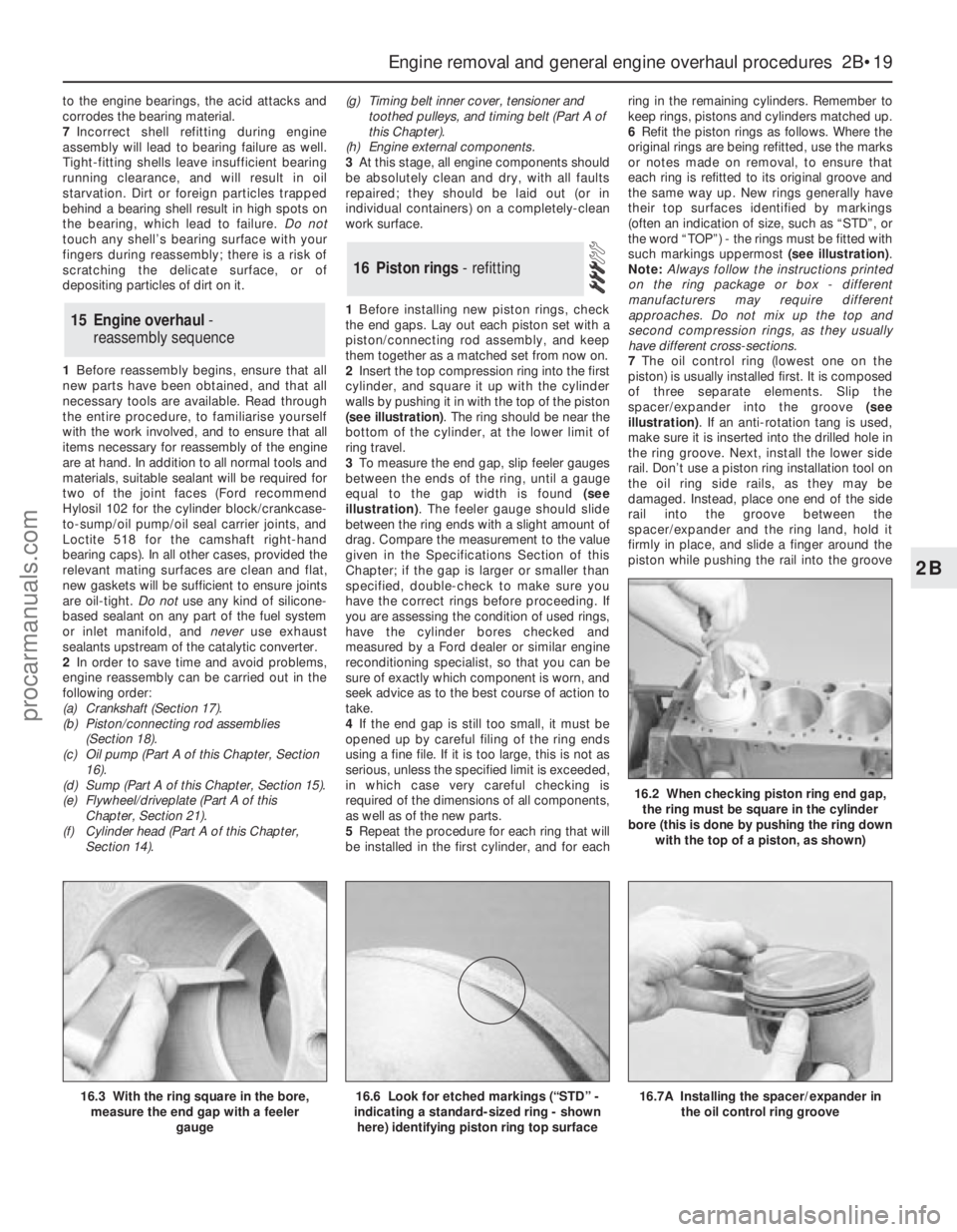
2Insert the top compression ring into the first
cylinder, and square it up with the cylinder
walls by pushing it in with the top of the piston
(see illustration). The ring should be near the
bottom of the cylinder, at the lower limit of
ring travel.
3To measure the end gap, slip feeler gauges
between the ends of the ring, until a gauge
equal to the gap width is found (see
illustration). The feeler gauge should slide
between the ring ends with a slight amount of
drag. Compare the measurement to the value
given in the Specifications Section of this
Chapter; if the gap is larger or smaller than
specified, double-check to make sure you
have the correct rings before proceeding. If
you are assessing the condition of used rings,
have the cylinder bores checked and
measured by a Ford dealer or similar engine
reconditioning specialist, so that you can be
sure of exactly which component is worn, and
seek advice as to the best course of action to
take.
4If the end gap is still too small, it must be
opened up by careful filing of the ring ends
using a fine file. If it is too large, this is not as
serious, unless the specified limit is exceeded,
in which case very careful checking is
required of the dimensions of all components,
as well as of the new parts.
5Repeat the procedure for each ring that will
be installed in the first cylinder, and for eachring in the remaining cylinders. Remember to
keep rings, pistons and cylinders matched up.
6Refit the piston rings as follows. Where the
original rings are being refitted, use the marks
or notes made on removal, to ensure that
each ring is refitted to its original groove and
the same way up. New rings generally have
their top surfaces identified by markings
(often an indication of size, such as “STD”, or
the word “TOP”) - the rings must be fitted with
such markings uppermost (see illustration).
Note:Always follow the instructions printed
on the ring package or box - different
manufacturers may require different
approaches. Do not mix up the top and
second compression rings, as they usually
have different cross-sections.
7The oil control ring (lowest one on the
piston) is usually installed first. It is composed
of three separate elements. Slip the
spacer/expander into the groove (see
illustration). If an anti-rotation tang is used,
make sure it is inserted into the drilled hole in
the ring groove. Next, install the lower side
rail. Don’t use a piston ring installation tool on
the oil ring side rails, as they may be
damaged. Instead, place one end of the side
rail into the groove between the
spacer/expander and the ring land, hold it
firmly in place, and slide a finger around the
piston while pushing the rail into the groove
16 Piston rings - refitting
15 Engine overhaul -
reassembly sequence
Engine removal and general engine overhaul procedures 2B•19
2B
16.7A Installing the spacer/expander in
the oil control ring groove
16.2 When checking piston ring end gap,
the ring must be square in the cylinder
bore (this is done by pushing the ring down
with the top of a piston, as shown)
16.3 With the ring square in the bore,
measure the end gap with a feeler
gauge16.6 Look for etched markings (“STD” -
indicating a standard-sized ring - shown
here) identifying piston ring top surface
procarmanuals.com
Page 116 of 279
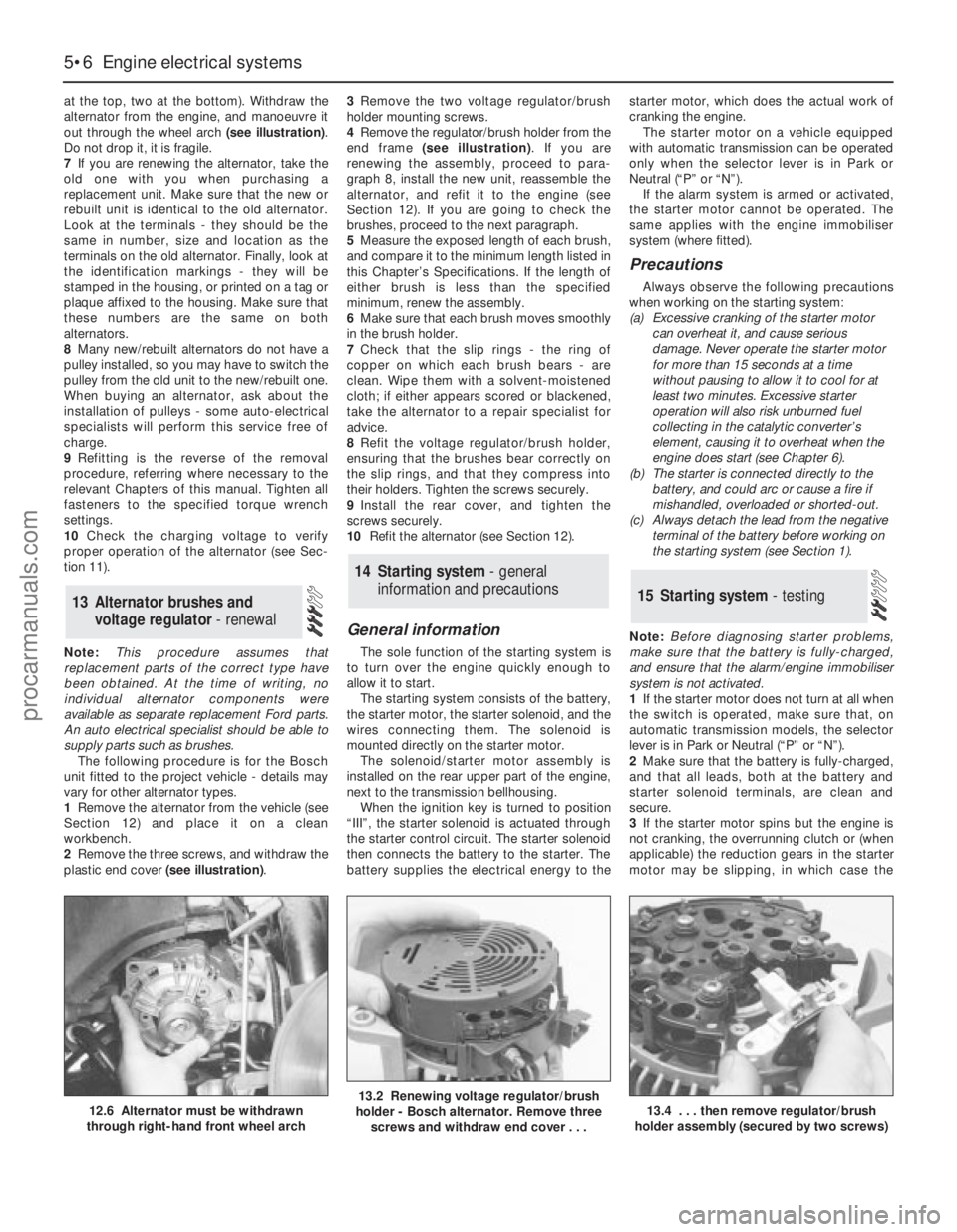
at the top, two at the bottom). Withdraw the
alternator from the engine, and manoeuvre it
out through the wheel arch (see illustration).
Do not drop it, it is fragile.
7If you are renewing the alternator, take the
old one with you when purchasing a
replacement unit. Make sure that the new or
rebuilt unit is identical to the old alternator.
Look at the terminals - they should be the
same in number, size and location as the
terminals on the old alternator. Finally, look at
the identification markings - they will be
stamped in the housing, or printed on a tag or
plaque affixed to the housing. Make sure that
these numbers are the same on both
alternators.
8Many new/rebuilt alternators do not have a
pulley installed, so you may have to switch the
pulley from the old unit to the new/rebuilt one.
When buying an alternator, ask about the
installation of pulleys - some auto-electrical
specialists will perform this service free of
charge.
9Refitting is the reverse of the removal
procedure, referring where necessary to the
relevant Chapters of this manual. Tighten all
fasteners to the specified torque wrench
settings.
10Check the charging voltage to verify
proper operation of the alternator (see Sec-
tion 11).
Note:This procedure assumes that
replacement parts of the correct type have
been obtained. At the time of writing, no
individual alternator components were
available as separate replacement Ford parts.
An auto electrical specialist should be able to
supply parts such as brushes.
The following procedure is for the Bosch
unit fitted to the project vehicle - details may
vary for other alternator types.
1Remove the alternator from the vehicle (see
Section 12) and place it on a clean
workbench.
2Remove the three screws, and withdraw the
plastic end cover (see illustration).3Remove the two voltage regulator/brush
holder mounting screws.
4Remove the regulator/brush holder from the
end frame (see illustration). If you are
renewing the assembly, proceed to para-
graph 8, install the new unit, reassemble the
alternator, and refit it to the engine (see
Section 12). If you are going to check the
brushes, proceed to the next paragraph.
5Measure the exposed length of each brush,
and compare it to the minimum length listed in
this Chapter’s Specifications. If the length of
either brush is less than the specified
minimum, renew the assembly.
6Make sure that each brush moves smoothly
in the brush holder.
7Check that the slip rings - the ring of
copper on which each brush bears - are
clean. Wipe them with a solvent-moistened
cloth; if either appears scored or blackened,
take the alternator to a repair specialist for
advice.
8Refit the voltage regulator/brush holder,
ensuring that the brushes bear correctly on
the slip rings, and that they compress into
their holders. Tighten the screws securely.
9Install the rear cover, and tighten the
screws securely.
10Refit the alternator (see Section 12).
General information
The sole function of the starting system is
to turn over the engine quickly enough to
allow it to start.
The starting system consists of the battery,
the starter motor, the starter solenoid, and the
wires connecting them. The solenoid is
mounted directly on the starter motor.
The solenoid/starter motor assembly is
installed on the rear upper part of the engine,
next to the transmission bellhousing.
When the ignition key is turned to position
“III”, the starter solenoid is actuated through
the starter control circuit. The starter solenoid
then connects the battery to the starter. The
battery supplies the electrical energy to thestarter motor, which does the actual work of
cranking the engine.
The starter motor on a vehicle equipped
with automatic transmission can be operated
only when the selector lever is in Park or
Neutral (“P” or “N”).
If the alarm system is armed or activated,
the starter motor cannot be operated. The
same applies with the engine immobiliser
system (where fitted).
Precautions
Always observe the following precautions
when working on the starting system:
(a) Excessive cranking of the starter motor
can overheat it, and cause serious
damage. Never operate the starter motor
for more than 15 seconds at a time
without pausing to allow it to cool for at
least two minutes. Excessive starter
operation will also risk unburned fuel
collecting in the catalytic converter’s
element, causing it to overheat when the
engine does start (see Chapter 6).
(b) The starter is connected directly to the
battery, and could arc or cause a fire if
mishandled, overloaded or shorted-out.
(c) Always detach the lead from the negative
terminal of the battery before working on
the starting system (see Section 1).
Note:Before diagnosing starter problems,
make sure that the battery is fully-charged,
and ensure that the alarm/engine immobiliser
system is not activated.
1If the starter motor does not turn at all when
the switch is operated, make sure that, on
automatic transmission models, the selector
lever is in Park or Neutral (“P” or “N”).
2Make sure that the battery is fully-charged,
and that all leads, both at the battery and
starter solenoid terminals, are clean and
secure.
3If the starter motor spins but the engine is
not cranking, the overrunning clutch or (when
applicable) the reduction gears in the starter
motor may be slipping, in which case the
15 Starting system - testing
14 Starting system - general
information and precautions
13 Alternator brushes and
voltage regulator - renewal
5•6 Engine electrical systems
12.6 Alternator must be withdrawn
through right-hand front wheel arch13.2 Renewing voltage regulator/brush
holder - Bosch alternator. Remove three
screws and withdraw end cover . . .13.4 . . . then remove regulator/brush
holder assembly (secured by two screws)
procarmanuals.com
Page 149 of 279
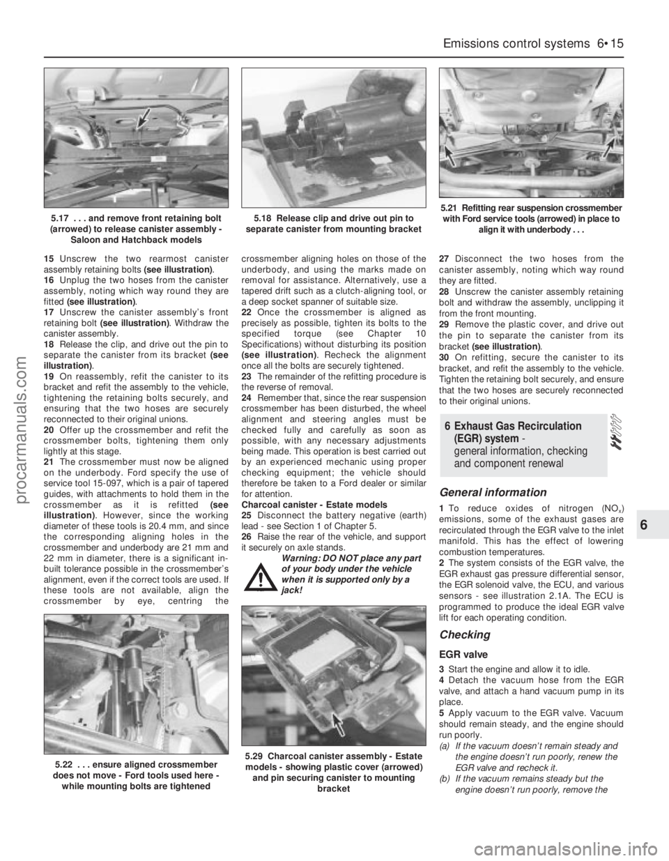
15Unscrew the two rearmost canister
assembly retaining bolts (see illustration).
16Unplug the two hoses from the canister
assembly, noting which way round they are
fitted (see illustration).
17Unscrew the canister assembly’s front
retaining bolt (see illustration). Withdraw the
canister assembly.
18Release the clip, and drive out the pin to
separate the canister from its bracket (see
illustration).
19On reassembly, refit the canister to its
bracket and refit the assembly to the vehicle,
tightening the retaining bolts securely, and
ensuring that the two hoses are securely
reconnected to their original unions.
20Offer up the crossmember and refit the
crossmember bolts, tightening them only
lightly at this stage.
21The crossmember must now be aligned
on the underbody. Ford specify the use of
service tool 15-097, which is a pair of tapered
guides, with attachments to hold them in the
crossmember as it is refitted (see
illustration). However, since the working
diameter of these tools is 20.4 mm, and since
the corresponding aligning holes in the
crossmember and underbody are 21 mm and
22 mm in diameter, there is a significant in-
built tolerance possible in the crossmember’s
alignment, even if the correct tools are used. If
these tools are not available, align the
crossmember by eye, centring thecrossmember aligning holes on those of the
underbody, and using the marks made on
removal for assistance. Alternatively, use a
tapered drift such as a clutch-aligning tool, or
a deep socket spanner of suitable size.
22Once the crossmember is aligned as
precisely as possible, tighten its bolts to the
specified torque (see Chapter 10
Specifications) without disturbing its position
(see illustration). Recheck the alignment
once all the bolts are securely tightened.
23The remainder of the refitting procedure is
the reverse of removal.
24Remember that, since the rear suspension
crossmember has been disturbed, the wheel
alignment and steering angles must be
checked fully and carefully as soon as
possible, with any necessary adjustments
being made. This operation is best carried out
by an experienced mechanic using proper
checking equipment; the vehicle should
therefore be taken to a Ford dealer or similar
for attention.
Charcoal canister - Estate models
25Disconnect the battery negative (earth)
lead - see Section 1 of Chapter 5.
26Raise the rear of the vehicle, and support
it securely on axle stands.
Warning: DO NOT place any part
of your body under the vehicle
when it is supported only by a
jack!27Disconnect the two hoses from the
canister assembly, noting which way round
they are fitted.
28Unscrew the canister assembly retaining
bolt and withdraw the assembly, unclipping it
from the front mounting.
29Remove the plastic cover, and drive out
the pin to separate the canister from its
bracket (see illustration).
30On refitting, secure the canister to its
bracket, and refit the assembly to the vehicle.
Tighten the retaining bolt securely, and ensure
that the two hoses are securely reconnected
to their original unions.
General information
1To reduce oxides of nitrogen (NOx)
emissions, some of the exhaust gases are
recirculated through the EGR valve to the inlet
manifold. This has the effect of lowering
combustion temperatures.
2The system consists of the EGR valve, the
EGR exhaust gas pressure differential sensor,
the EGR solenoid valve, the ECU, and various
sensors - see illustration 2.1A. The ECU is
programmed to produce the ideal EGR valve
lift for each operating condition.
Checking
EGR valve
3Start the engine and allow it to idle.
4Detach the vacuum hose from the EGR
valve, and attach a hand vacuum pump in its
place.
5Apply vacuum to the EGR valve. Vacuum
should remain steady, and the engine should
run poorly.
(a) If the vacuum doesn’t remain steady and
the engine doesn’t run poorly, renew the
EGR valve and recheck it.
(b) If the vacuum remains steady but the
engine doesn’t run poorly, remove the
6 Exhaust Gas Recirculation
(EGR) system-
general information, checking
and component renewal
Emissions control systems 6•15
6
5.22 . . . ensure aligned crossmember
does not move - Ford tools used here -
while mounting bolts are tightened5.29 Charcoal canister assembly - Estate
models - showing plastic cover (arrowed)
and pin securing canister to mounting
bracket
5.17 . . . and remove front retaining bolt
(arrowed) to release canister assembly -
Saloon and Hatchback models5.18 Release clip and drive out pin to
separate canister from mounting bracket5.21 Refitting rear suspension crossmember
with Ford service tools (arrowed) in place to
align it with underbody . . .
procarmanuals.com