1993 FORD MONDEO jump cable
[x] Cancel search: jump cablePage 93 of 279

sender’s electrical connector, and use a
jumper wire to connect the white/red wire to a
clean earth point (bare metal) on the engine.
Switch on the ignition without starting the
engine. If the gauge now indicates Hot, renew
the sender.
5If the gauge still does not work, the circuit
may be open, or the gauge may be faulty. See
Chapter 12 for additional information.
Removal
6Unbolt the resonator support bracket from
the engine compartment front crossmember.
Slacken the two clamp screws securing the
resonator to the air mass meter and plenum
chamber hoses, then swing the resonator up
clear of the thermostat housing (see Chap-
ter 4).
7Drain the cooling system (see Chapter 1).
8Disconnect the expansion tank coolant
hose and the radiator top hose from the
thermostat housing’s water outlet, then
disconnect the metal coolant pipe/hose from
the thermostat.
9Unplug the electrical connector from the
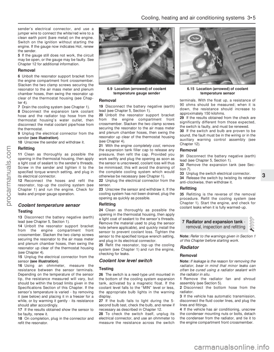
sender (see illustration).
10Unscrew the sender and withdraw it.
Refitting
11Clean as thoroughly as possible the
opening in the thermostat housing, then apply
a light coat of sealant to the sender’s threads.
Screw in the sender and tighten it to the
specified torque wrench setting, and plug in
its electrical connector.
12Reconnect the hoses and refit the
resonator, top-up the cooling system (see
Chapter 1) and run the engine. Check for
leaks and proper gauge operation.
Coolant temperature sensor
Testing
13Disconnect the battery negative (earth)
lead (see Chapter 5, Section 1).
14Unbolt the resonator support bracket
from the engine compartment front
crossmember. Slacken the two clamp screws
securing the resonator to the air mass meter
and plenum chamber hoses, then swing the
resonator up clear of the thermostat housing
(see Chapter 4).
15Unplug the electrical connector from the
sensor (see illustration).
16Using an ohmmeter, measure the
resistance between the sensor terminals.
Depending on the temperature of the sensor
tip, the resistance measured will vary, but
should be within the broad limits given in the
Specifications Section of this Chapter. If the
sensor’s temperature is varied - by removing
it (see below) and placing it in a freezer for a
while, or by warming it gently - its resistance
should alter accordingly.
17If the results obtained show the sensor to
be faulty, renew it.
18On completion, plug in the connector and
refit the resonator.
Removal
19Disconnect the battery negative (earth)
lead (see Chapter 5, Section 1).
20Unbolt the resonator support bracket
from the engine compartment front
crossmember. Slacken the two clamp screws
securing the resonator to the air mass meter
and plenum chamber hoses, then swing the
resonator up clear of the thermostat housing
(see Chapter 4).
21With the engine completely cool, remove
the expansion tank filler cap to release any
pressure, then refit the cap. Provided you
work swiftly and plug the opening as soon as
the sensor is unscrewed, coolant loss will thus
be minimised; this will avoid the draining of
the complete cooling system which would
otherwise be necessary (see Chapter 1).
22Unplug the electrical connector from the
sensor.
23Unscrew the sensor and withdraw it. If the
cooling system has not been drained, plug the
opening as quickly as possible.
Refitting
24Clean as thoroughly as possible the
opening in the thermostat housing, then apply
a light coat of sealant to the sensor’s threads.
Remove the material used to plug the sensor
hole (where applicable), and quickly install the
sensor to prevent coolant loss. Tighten the
sensor to the specified torque wrench setting,
and plug in its electrical connector.
25Refit the resonator, top-up the cooling
system (see Chapter 1) and run the engine,
checking for leaks.
Coolant low level switch
Testing
26The switch is a reed-type unit mounted in
the bottom of the cooling system expansion
tank, activated by a magnetic float. If the
coolant level falls to the “MIN” level or less,
the appropriate bulb lights in the warning
display.
27If the bulb fails to light during the 5-
second bulb test, check the bulb, and renew if
necessary as described in Chapter 12.
28To check the switch itself, unplug its
electrical connector, and use an ohmmeter to
measure the resistance across the switchterminals. With the float up, a resistance of
90 ohms should be measured; when it is
down, the resistance should increase to
approximately 150 kilohms.
29If the results obtained from the check are
significantly different from those expected,
the switch is faulty, and must be renewed.
30If the switch and bulb are proven to be
sound, the fault must be in the wiring or in the
auxiliary warning control assembly (see
Chapter 12).
Removal
31Disconnect the battery negative (earth)
lead (see Chapter 5, Section 1).
32Remove the expansion tank (see Sec-
tion 7).
33Unplug the switch electrical connector.
34Release the switch by twisting its retainer
anti-clockwise, then withdraw it.
Refitting
35Refitting is the reverse of the removal
procedure. Refill the cooling system (see
Chapter 1). Start the engine, and check for
coolant leaks when it is fully warmed-up.
Note:Refer to the warnings given in Section 1
of this Chapter before starting work.
Radiator
Removal
Note:If leakage is the reason for removing the
radiator, bear in mind that minor leaks can
often be cured using a radiator sealant with
the radiator in situ.
1Remove the radiator fan and shroud
assembly (see Section 5).
2Disconnect the bottom hose from the
radiator.
3If the vehicle has automatic transmission,
disconnect the fluid cooler lines, and plug the
lines and fittings.
4If the vehicle has air conditioning, unscrew
the condenser mounting nuts or bolts, detach
the condenser from the radiator, and tie it to
the engine compartment front crossmember.
7 Radiator and expansion tank -
removal, inspection and refitting
Cooling, heating and air conditioning systems 3•5
3
6.9 Location (arrowed) of coolant
temperature gauge sender6.15 Location (arrowed) of coolant
temperature sensor
procarmanuals.com
Page 205 of 279

compartment, but on Estate models, it is on
the right-hand side.
Some models are fitted with a headlight
levelling system, which is controlled by a knob
on the facia. On position “0”, the headlights
are in their base position, and on position “5”,
the headlights are in their maximum inclined
angle.
It should be noted that, when portions of
the electrical system are serviced, the cable
should be disconnected from the battery
negative terminal, to prevent electrical shorts
and fires.
Caution: When disconnecting the
battery for work described in the
following Sections, refer to
Chapter 5, Section 1.
Note:Refer to the precautions given in
“Safety first!” and in Section 1 of this Chapter
before starting work. The following tests relate
to testing of the main electrical circuits, and
should not be used to test delicate electronic
circuits (such as engine management systems,
anti-lock braking systems, etc), particularly
where an electronic control module is used.
Also refer to the precautions given in Chapter
5, Section 1.
General
1A typical electrical circuit consists of an
electrical component, any switches, relays,
motors, fuses, fusible links or circuit breakers
related to that component, and the wiring and
connectors which link the component to both
the battery and the chassis. To help to
pinpoint a problem in an electrical circuit,
wiring diagrams are included at the end of this
manual.
2Before attempting to diagnose an electrical
fault, first study the appropriate wiring
diagram, to obtain a complete understanding
of the components included in the particular
circuit concerned. The possible sources of a
fault can be narrowed down by noting if other
components related to the circuit are
operating properly. If several components or
circuits fail at one time, the problem is likely to
be related to a shared fuse or earth
connection.
3Electrical problems usually stem from
simple causes, such as loose or corroded
connections, a faulty earth connection, a
blown fuse, a melted fusible link, or a faulty
relay (refer to Section 3 for details of testing
relays). Visually inspect the condition of all
fuses, wires and connections in a problem
circuit before testing the components. Use
the wiring diagrams to determine which
terminal connections will need to be checked
in order to pinpoint the trouble-spot.
4The basic tools required for electrical fault-
finding include a circuit tester or voltmeter (a
12-volt bulb with a set of test leads can alsobe used for certain tests); an ohmmeter (to
measure resistance and check for continuity);
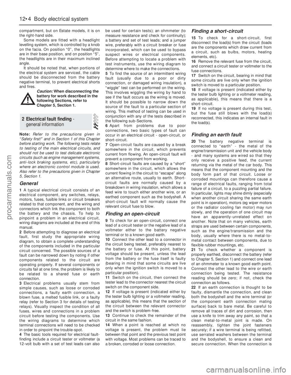
a battery and set of test leads; and a jumper
wire, preferably with a circuit breaker or fuse
incorporated, which can be used to bypass
suspect wires or electrical components.
Before attempting to locate a problem with
test instruments, use the wiring diagram to
determine where to make the connections.
5To find the source of an intermittent wiring
fault (usually due to a poor or dirty
connection, or damaged wiring insulation), a
“wiggle” test can be performed on the wiring.
This involves wiggling the wiring by hand to
see if the fault occurs as the wiring is moved.
It should be possible to narrow down the
source of the fault to a particular section of
wiring. This method of testing can be used in
conjunction with any of the tests described in
the following sub-Sections.
6Apart from problems due to poor
connections, two basic types of fault can
occur in an electrical circuit - open-circuit, or
short-circuit.
7Open-circuit faults are caused by a break
somewhere in the circuit, which prevents
current from flowing. An open-circuit fault will
prevent a component from working.
8Short-circuit faults are caused by a “short”
somewhere in the circuit, which allows the
current flowing in the circuit to “escape” along
an alternative route, usually to earth. Short-
circuit faults are normally caused by a
breakdown in wiring insulation, which allows a
feed wire to touch either another wire, or an
earthed component such as the bodyshell. A
short-circuit fault will normally cause the
relevant circuit fuse to blow.
Finding an open-circuit
9To check for an open-circuit, connect one
lead of a circuit tester or the negative lead of a
voltmeter either to the battery negative
terminal or to a known good earth.
10Connect the other lead to a connector in
the circuit being tested, preferably nearest to
the battery or fuse. At this point, battery
voltage should be present, unless the lead
from the battery or the fuse itself is faulty
(bearing in mind that some circuits are live
only when the ignition switch is moved to a
particular position).
11Switch on the circuit, then connect the
tester lead to the connector nearest the circuit
switch on the component side.
12If voltage is present (indicated either by
the tester bulb lighting or a voltmeter reading,
as applicable), this means that the section of
the circuit between the relevant connector
and the switch is problem-free.
13Continue to check the remainder of the
circuit in the same fashion.
14When a point is reached at which no
voltage is present, the problem must lie
between that point and the previous test point
with voltage. Most problems can be traced to
a broken, corroded or loose connection.
Finding a short-circuit
15To check for a short-circuit, first
disconnect the load(s) from the circuit (loads
are the components which draw current from
a circuit, such as bulbs, motors, heating
elements, etc).
16Remove the relevant fuse from the circuit,
and connect a circuit tester or voltmeter to the
fuse connections.
17Switch on the circuit, bearing in mind that
some circuits are live only when the ignition
switch is moved to a particular position.
18If voltage is present (indicated either by
the tester bulb lighting or a voltmeter reading,
as applicable), this means that there is a
short-circuit.
19If no voltage is present during this test,
but the fuse still blows with the load(s)
reconnected, this indicates an internal fault in
the load(s).
Finding an earth fault
20The battery negative terminal is
connected to “earth” - the metal of the
engine/transmission unit and the vehicle body
- and many systems are wired so that they
only receive a positive feed, the current
returning via the metal of the car body. This
means that the component mounting and the
body form part of that circuit. Loose or
corroded mountings can therefore cause a
range of electrical faults, ranging from total
failure of a circuit, to a puzzling partial failure.
In particular, lights may shine dimly (especially
when another circuit sharing the same earth
point is in operation), motors (eg wiper motors
or the radiator cooling fan motor) may run
slowly, and the operation of one circuit may
have an apparently-unrelated effect on
another. Note that on many vehicles, earth
straps are used between certain components,
such as the engine/transmission and the
body, usually where there is no metal-to-
metal contact between components, due to
flexible rubber mountings, etc.
21To check whether a component is
properly earthed, disconnect the battery (refer
to Chapter 5, Section 1) and connect one lead
of an ohmmeter to a known good earth point.
Connect the other lead to the wire or earth
connection being tested. The resistance
reading should be zero; if not, check the
connection as follows.
22If an earth connection is thought to be
faulty, dismantle the connection, and clean
both the bodyshell and the wire terminal (or
the component earth connection mating
surface) back to bare metal. Be careful to
remove all traces of dirt and corrosion, then
use a knife to trim away any paint, so that a
clean metal-to-metal joint is made. On
reassembly, tighten the joint fasteners
securely; if a wire terminal is being refitted,
use serrated washers between the terminal
and the bodyshell, to ensure a clean and
secure connection. When the connection is
2 Electrical fault finding -
general information
12•4 Body electrical system
procarmanuals.com
Page 268 of 279

REF•9
Excessive fuel consumption
m mUnsympathetic driving style, or adverse conditions.
m mAir filter element dirty or clogged (Chapter 1).
m mEngine management system fault (Chapters 1, 4, 5 and 6).
m mIgnition timing incorrect (Chapters 5 and 6).
m mTyres under-inflated (Chapter 1).
Fuel leakage and/or fuel odour
m
mDamaged or corroded fuel tank, pipes or connections (Chapter 1).
m mCharcoal canister and/or connecting pipes leaking (Chapter 6).
Excessive noise or fumes from exhaust system
m
mLeaking exhaust system or manifold joints (Chapters 1, 2 Part A,
and 4).
m mLeaking, corroded or damaged silencers or pipe (Chapter 1).
m mBroken mountings, causing body or suspension contact (Chap-
ters 1 and 4).
Fault Finding
3 Fuel and exhaust system
Noisy in neutral with engine running
m mInput shaft bearings worn (noise apparent with clutch pedal
released, but not when depressed) (Chapter 7, Part A).*
m mClutch release bearing worn (noise apparent with clutch pedal
depressed, possibly less when released) (Chapter 8).
Noisy in one particular gear
m mWorn, damaged or chipped gear teeth (Chapter 7, Part A).*
Difficulty engaging gears
m
mClutch fault (Chapter 8).
m mWorn or damaged gear linkage (Chapter 7, Part A).
m mIncorrectly-adjusted gear linkage (Chapter 7, Part A).
m mWorn synchroniser assemblies (Chapter 7, Part A).*
Vibration
m
mLack of oil (Chapter 1).
m mWorn bearings (Chapter 7, Part A).*
Jumps out of gear
m
mWorn or damaged gear linkage (Chapter 7, Part A).
m mIncorrectly-adjusted gear linkage (Chapter 7, Part A).
m mWorn synchroniser assemblies (Chapter 7, Part A).*
m mWorn selector forks (Chapter 7, Part A).*
Lubricant leaks
m
mLeaking differential side gear oil seal (Chapter 7, Part A).
m mLeaking housing joint (Chapter 7, Part A).*
m mLeaking input shaft oil seal (Chapter 7, Part A).*
m mLeaking selector shaft oil seal (Chapter 7, Part A).
m mLeaking speedometer drive pinion O-ring (Chapter 7, Part A).
* Although the corrective action necessary to remedy the symptoms
described is beyond the scope of the home mechanic, the above
information should be helpful in isolating the cause of the condition, so
that the owner can communicate clearly with a professional mechanic.
4 Clutch
5 Manual transmission
Pedal travels to floor - no pressure or very little
resistance
m mBroken clutch cable (Chapter 8).
m mIncorrect clutch adjustment (Chapter 8).
m mBroken clutch release bearing or fork (Chapter 8).
m mBroken diaphragm spring in clutch pressure plate (Chapter 8).
Clutch fails to disengage (unable to select gears)
m
mIncorrect clutch adjustment (Chapter 8).
m mClutch disc sticking on transmission input shaft splines (Chapter 8).
m mClutch disc sticking to flywheel or pressure plate (Chapter 8).
m mFaulty pressure plate assembly (Chapter 8).
m mClutch release mechanism worn or incorrectly assembled (Chapter 8).
Clutch slips (engine speed increases with no
increase in vehicle speed)
m mIncorrect clutch adjustment (Chapter 8).
m mClutch disc linings excessively worn (Chapter 8).m mClutch disc linings contaminated with oil or grease (Chapter 8).
m mFaulty pressure plate or weak diaphragm spring (Chapter 8).
Judder as clutch is engaged
m
mClutch disc linings contaminated with oil or grease (Chapter 8).
m mClutch disc linings excessively worn (Chapter 8).
m mClutch cable sticking or frayed (Chapter 8).
m mFaulty or distorted pressure plate or diaphragm spring (Chapter 8).
m mWorn or loose engine/transmission mountings (Chapter 2, Part A).
m mClutch disc hub or transmission input shaft splines worn (Chap-
ter 8).
Noise when depressing or releasing clutch pedal
m mWorn clutch release bearing (Chapter 8).
m mWorn or dry clutch pedal bushes (Chapter 8).
m mFaulty pressure plate assembly (Chapter 8).
m mPressure plate diaphragm spring broken (Chapter 8).
m mBroken clutch disc cushioning springs (Chapter 8).
Internal coolant leakage
m
mLeaking cylinder head gasket (Chapter 2, Part A).
m mCracked cylinder head or cylinder bore (Chapter 2, Part B).
Corrosion
m
mInfrequent draining and flushing (Chapter 1).
m mIncorrect antifreeze mixture, or inappropriate antifreeze type
(Chapter 1).
procarmanuals.com
Page 276 of 279

REF•17Index
A
A pillar trim - 11•20
ABS - 9•14
Accelerator cable - 4•4
Accelerator pedal - 4•5
Accumulator - 3•9
Acknowledgements - 0•4
Adaptive damping switch - 12•8
Aerial - 12•22
Air bag - 0•5, 1•22, 12•22
Air cleaner - 4•3, 6•19
Air conditioning - 1•15, 3•2, 3•8, 3•9, 6•11
Air distribution control - 3•8
Air induction system - 4•9
Air intake components - 4•3
Air mass meter - 4•3, 6•10, 6•11, 6•12
Air temperature warning sender unit -
12•18
Alarm - 11•17, 12•18
Alternator - 5•5, 5•6
Amplifier - 12•21
Anti-lock Braking System - 9•14
Anti-roll bar - 10•8, 10•12, 10•15
Anti-theft alarm system - 12•18
Antifreeze - 1•2, 1•22, 3•2
Asbestos - 0•5
ATF - 1•2
Automatic transmission- 1•11, 1•17,
2A•24, 2B•3, 2B•4, 6•11, 7B•1et seq,
12•11
Automatic transmission fault finding -
REF•10
Automatic transmission fluid - 1•2
Auxiliary drivebelt - 1•13
Auxiliary warning system - 12•17
B
B pillar trim - 11•20
Backfire - REF•8
Backrest - 11•18
Battery - 0•5, 1•8, 1•11, 5•2, 5•3
Battery fault - REF•12
Big-end bearings - 2B•18, 2B•21
Bleeding brakes - 9•12
Bleeding power steering - 10•21
Blower/air conditioning control - 3•8Body corrosion - 0•10
Body electrical system- 12•1et seq
Bodywork and fittings- 11•1et seq
Bonnet - 1•20, 11•5, 11•6
Booster battery (jump) starting - 0•12
Boot - 11•14, 11•15
Brake check - 1•19
Brake fluid - 1•2, 1•8, 1•26
Brake line check - 1•19
Braking system- 0•7, 0•8, 0•9, 1•20, 9•1et
seq
Braking system fault finding - REF•10
Brush renewal - 5•8
Bulb failure module - 12•18
Bulbs - 12•8, 12•11, 12•18
Bumpers - 11•4, 11•5
Burning - 0•5
C
C pillar trim - 11•20, 11•21
Cables - 4•4, 7B•2, 8•2, 9•16, 11•6, 12•15
Calipers - 9•4, 9•9
Camshaft - 2A•13, 2A•14, 6•11, 6•12
Cassette player - 12•21
Catalytic converter - 6•19
CD player - 12•22
Central locking system - 11•17
Central locking system fault - REF•12
Centre console - 11•21
Charcoal canister - 6•14
Charging - 1•12, 5•5
Check strap - 11•13
Clock - 12•11, 12•15
Clutch and driveshafts- 1•17, 1•20, 8•1et
seq
Clutch fault finding - REF•9
CO emissions (mixture) - 0•10
Coil spring - 10•15
Compact disc player - 12•22
Compression test - 2A•5
Compressor - 3•9
Condenser - 3•9
Connecting rods - 2B•12, 2B•17, 2B•21,
2B•22
Console - 11•21, 11•22
Contents - 0•2
Conversion factors - 0•14Coolant - 1•2, 1•6, 1•7, 1•21
Coolant leakage - REF•9
Coolant low level switch - 3•5
Coolant temperature gauge sender - 3•4
Coolant temperature sensor - 3•5, 6•11,
6•13
Coolant warning switch - 12•18
Cooling, heating, and air conditioning
systems- 1•22, 3•1et seq
Cooling, heating, and air conditioning
systems fault finding - REF•8
Corrosion - REF•9
Courtesy light - 12•8
Crankcase - 2B•13
Crankshaft - 2A•9, 2A•13, 2A•22, 2B•13,
2B•18, 2B•20, 5•4, 6•10, 6•11, 6•12
Crossmember - 10•13, 10•17
Cruise control system - 12•19
Crushing - 0•5
Cushion - 11•18
CV joints - 1•18, 8•7, 8•9
Cylinder block - 2B•13
Cylinder head - 2A•6, 2A•17, 2B•9, 2B•10,
2B•11, 6•19
D
D pillar trim - 11•21
Damping switch - 12•8
Dehydrator - 3•9
Dents in bodywork - 11•3
Depressurisation - 4•2
Diagnosis system - 6•4
Differential - 7A•2, 7B•3
Dimensions - 0•6
Dipped beam switch - 12•7
Direction indicators - 12•7, 12•9, 12•12
Discs - 1•19, 9•5, 9•10
Display warning bulb - 12•18
Doors - 0•8, 1•20, 11•6, 11•7, 11•8, 11•9,
11•10, 11•11, 11•13, 12•7, 12•8, 12•11,
12•18
Drivebelts - 1•13
Driveplate - 2A•24
Driveshafts - 0•9, 1•18, 8•5, 8•6, 8•7, 8•9,
8•10
Driveshafts fault finding - REF•10
Drivetrain - 1•20
Drums - 1•19, 9•6 Note: References throughout this index relate to Chapter•page number
procarmanuals.com