1993 FORD MONDEO sport mode
[x] Cancel search: sport modePage 112 of 279
General information
The engine electrical systems include all
ignition, charging and starting components.
Because of their engine-related functions,
these components are discussed separately
from body electrical devices such as the
lights, the instruments, etc (which are
included in Chapter 12).
Precautions
Always observe the following precautions
when working on the electrical system:
(a) Be extremely careful when servicing
engine electrical components. They are
easily damaged if checked, connected or
handled improperly.
(b) Never leave the ignition switched on for
long periods of time when the engine is
not running.
(c) Don’t disconnect the battery leads while
the engine is running.
(d) Maintain correct polarity when connecting
a battery lead from another vehicle during
jump starting - see the “Booster battery
(jump) starting” section at the front of this
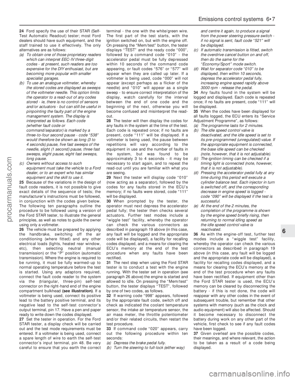
manual.
(e) Always disconnect the negative lead first,
and reconnect it last, or the battery may
be shorted by the tool being used to
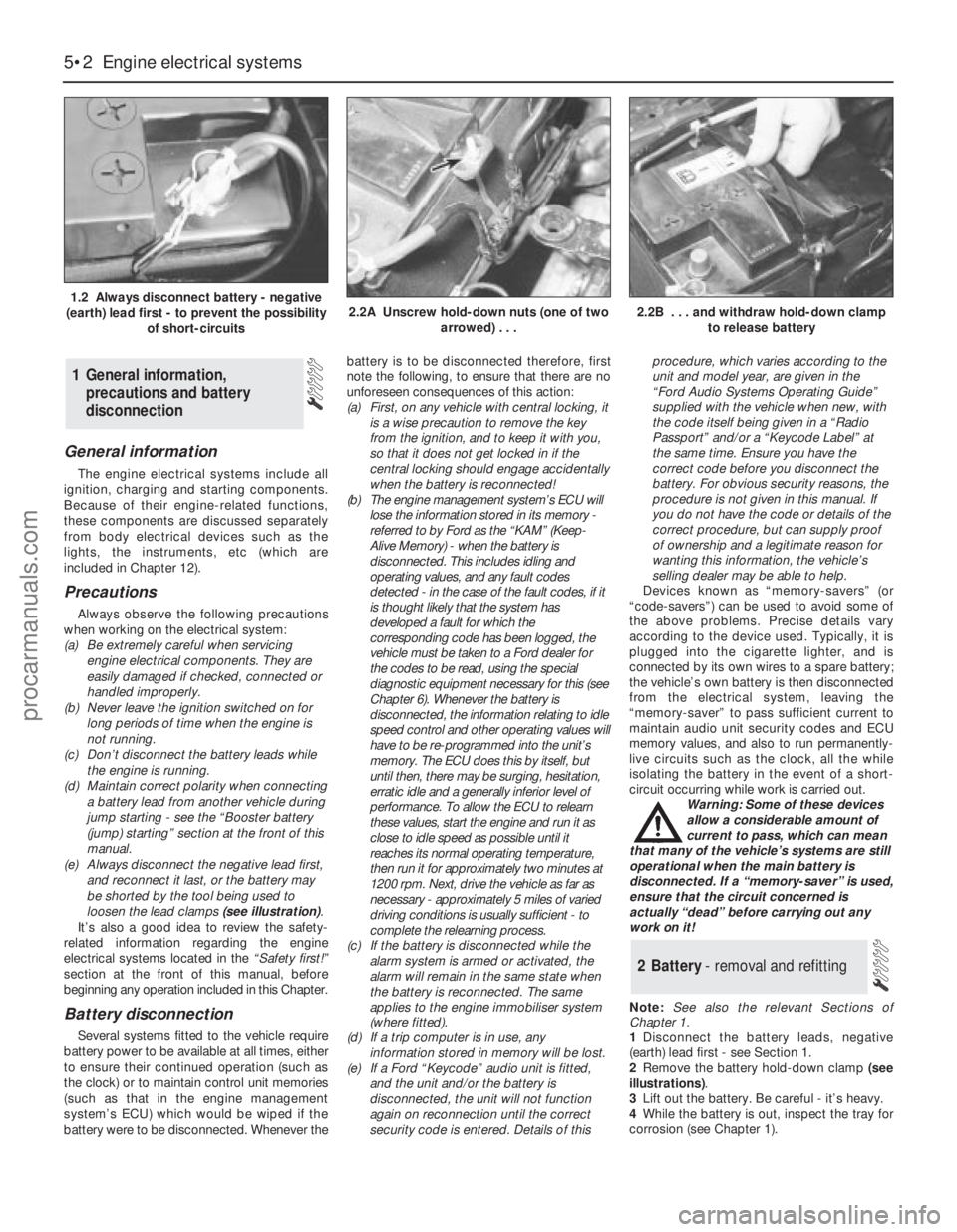
loosen the lead clamps (see illustration).
It’s also a good idea to review the safety-
related information regarding the engine
electrical systems located in the “Safety first!”
section at the front of this manual, before
beginning any operation included in this Chapter.
Battery disconnection
Several systems fitted to the vehicle require
battery power to be available at all times, either
to ensure their continued operation (such as
the clock) or to maintain control unit memories
(such as that in the engine management
system’s ECU) which would be wiped if the
battery were to be disconnected. Whenever thebattery is to be disconnected therefore, first
note the following, to ensure that there are no
unforeseen consequences of this action:
(a) First, on any vehicle with central locking, it
is a wise precaution to remove the key
from the ignition, and to keep it with you,
so that it does not get locked in if the
central locking should engage accidentally
when the battery is reconnected!
(b) The engine management system’s ECU will
lose the information stored in its memory -
referred to by Ford as the “KAM” (Keep-
Alive Memory) - when the battery is
disconnected. This includes idling and
operating values, and any fault codes
detected - in the case of the fault codes, if it
is thought likely that the system has
developed a fault for which the
corresponding code has been logged, the
vehicle must be taken to a Ford dealer for
the codes to be read, using the special
diagnostic equipment necessary for this (see
Chapter 6). Whenever the battery is
disconnected, the information relating to idle
speed control and other operating values will
have to be re-programmed into the unit’s
memory. The ECU does this by itself, but
until then, there may be surging, hesitation,
erratic idle and a generally inferior level of
performance. To allow the ECU to relearn
these values, start the engine and run it as
close to idle speed as possible until it
reaches its normal operating temperature,
then run it for approximately two minutes at
1200 rpm. Next, drive the vehicle as far as
necessary - approximately 5 miles of varied
driving conditions is usually sufficient - to
complete the relearning process.
(c) If the battery is disconnected while the
alarm system is armed or activated, the
alarm will remain in the same state when
the battery is reconnected. The same
applies to the engine immobiliser system
(where fitted).
(d) If a trip computer is in use, any
information stored in memory will be lost.
(e) If a Ford “Keycode” audio unit is fitted,
and the unit and/or the battery is
disconnected, the unit will not function
again on reconnection until the correct
security code is entered. Details of thisprocedure, which varies according to the
unit and model year, are given in the
“Ford Audio Systems Operating Guide”
supplied with the vehicle when new, with
the code itself being given in a “Radio
Passport” and/or a “Keycode Label” at
the same time. Ensure you have the
correct code before you disconnect the
battery. For obvious security reasons, the
procedure is not given in this manual. If
you do not have the code or details of the
correct procedure, but can supply proof
of ownership and a legitimate reason for
wanting this information, the vehicle’s
selling dealer may be able to help.
Devices known as “memory-savers” (or
“code-savers”) can be used to avoid some of
the above problems. Precise details vary
according to the device used. Typically, it is
plugged into the cigarette lighter, and is
connected by its own wires to a spare battery;
the vehicle’s own battery is then disconnected
from the electrical system, leaving the
“memory-saver” to pass sufficient current to
maintain audio unit security codes and ECU
memory values, and also to run permanently-
live circuits such as the clock, all the while
isolating the battery in the event of a short-
circuit occurring while work is carried out.
Warning: Some of these devices
allow a considerable amount of
current to pass, which can mean
that many of the vehicle’s systems are still
operational when the main battery is
disconnected. If a “memory-saver” is used,
ensure that the circuit concerned is
actually “dead” before carrying out any
work on it!
Note:See also the relevant Sections of
Chapter 1.
1Disconnect the battery leads, negative
(earth) lead first - see Section 1.
2Remove the battery hold-down clamp (see
illustrations).
3Lift out the battery. Be careful - it’s heavy.
4While the battery is out, inspect the tray for
corrosion (see Chapter 1).
2 Battery- removal and refitting
1 General information,
precautions and battery
disconnection
5•2 Engine electrical systems
1.2 Always disconnect battery - negative
(earth) lead first - to prevent the possibility
of short-circuits2.2A Unscrew hold-down nuts (one of two
arrowed) . . .2.2B . . . and withdraw hold-down clamp
to release battery
procarmanuals.com
Page 141 of 279
24Ford specify the use of their STAR (Self-
Test Automatic Readout) tester; most Ford
dealers should have such equipment, and the
staff trained to use it effectively. The only
alternatives are as follows:
(a) To obtain one of those proprietary readers
which can interpret EEC-IV three-digit
codes - at present, such readers are too
expensive for the DIY enthusiast, but are
becoming more popular with smaller
specialist garages.
(b) To use an analogue voltmeter, whereby
the stored codes are displayed as sweeps
of the voltmeter needle. This option limits
the operator to a read-out of any codes
stored - ie, there is no control of sensors
and/or actuators - but can still be useful in
pinpointing the faulty part of the engine
management system. The display is
interpreted as follows. Each code
(whether fault code or
command/separator) is marked by a
three-to-four second pause - code “538”
would therefore be shown as long (3 to
4 seconds) pause, five fast sweeps of the
needle, slight (1 second) pause, three fast
sweeps, slight pause, eight fast sweeps,
long pause.
(c) Owners without access to such
equipment must take the vehicle to a Ford
dealer, or to an expert who has similar
equipment and the skill to use it.
25Because of the variations in the design of
fault code readers, it is not possible to give
exact details of the sequence of tests; the
manufacturer’s instructions must be followed,
in conjunction with the codes given below.
The following ten paragraphs outline the
procedure to be followed using a version of
the Ford STAR tester, to illustrate the general
principles, as well as notes to guide the owner
using only a voltmeter.
26The vehicle must be prepared by applying
the handbrake, switching off the air
conditioning (where fitted) and any other
electrical loads (lights, heated rear window,
etc), then selecting neutral (manual
transmission) or the “P” position (automatic
transmission). Where the engine is required to
be running, it must be fully warmed-up to
normal operating temperature before the test
is started. Using any adaptors required,
connect the fault code reader to the system
via the (triangular, three-pin) self-test
connector on the right-hand end of the engine
compartment bulkhead (see illustration). If a
voltmeter is being used, connect its positive
lead to the battery positive terminal, and its
negative lead to the self-test connector’s
output terminal, pin 17. Have a pen and paper
ready to write down the codes displayed.
27Set the tester in operation. For the Ford
STAR tester, a display check will be carried
out and the test mode requirements must be
entered. If a voltmeter is being used, connect
a spare length of wire to earth the self-test
connector’s input terminal, pin 48. Be very
careful to ensure that you earth the correctterminal - the one with the white/green wire.
The first part of the test starts, with the
ignition switched on, but with the engine off.
On pressing the “Mem/test” button, the tester
displays “TEST” and the ready code “000”,
followed by a command code “010” - the
accelerator pedal must be fully depressed
within 10 seconds of the command code
appearing, or fault codes “576” or “577” will
appear when they are called up later. If a
voltmeter is being used, code “000” will not
appear (except perhaps as a flicker of the
needle) and “010” will appear as a single
sweep - to ensure correct interpretation of the
display, watch carefully for the interval
between the end of one code and the
beginning of the next, otherwise you will
become confused and misinterpret the read-
out.
28The tester will then display the codes for
any faults in the system at the time of the test.
Each code is repeated once; if no faults are
present, code “111” will be displayed. If a
voltmeter is being used, the pause between
repetitions will vary according to the
equipment in use and the number of faults in
the system, but was found to be
approximately 3 to 4 seconds - it may be
necessary to start again, and to repeat the
read-out until you are familiar with what you
are seeing.
29Next the tester will display code “010”
(now acting as a separator), followed by the
codes for any faults stored in the ECU’s
memory; if no faults were stored, code “111”
will be displayed.
30When prompted by the tester, the
operator must next depress the accelerator
pedal fully; the tester then checks several
actuators. Further test modes include a
“wiggle test” facility, whereby the operator
can check the various connectors as
described in paragraph 19 above (in this case,
any fault will be logged and the appropriate
code will be displayed), a facility for recalling
codes displayed, and a means for clearing the
ECU’s memory at the end of the test
procedure when any faults have been
rectified.
31The next step when using the Ford STAR
tester is to conduct a test with the engine
running. With the tester set in operation (see
paragraph 26 above) the engine is started and
allowed to idle. On pressing the “Mem/test”
button, the tester displays “TEST”, followed
by one of two codes, as follows.
32If warning code “998” appears, followed
by the appropriate fault code, switch off and
check as indicated the coolant temperature
sensor, the intake air temperature sensor, the
air mass meter, the throttle potentiometer
and/or their related circuits, then restart the
test procedure.
33If command code “020” appears, carry
out the following procedure within ten
seconds:
(a) Depress the brake pedal fully.
(b) Turn the steering to full-lock (either way)and centre it again, to produce a signal
from the power steering pressure switch -
if no signal is sent, fault code “521” will
be displayed.
(c) If automatic transmission is fitted, switch
the overdrive cancel button on and off,
then do the same for the
“Economy/Sport” mode switch.
(d) Wait for separator code “010” to be
displayed, then within 10 seconds,
depress the accelerator pedal fully,
increasing engine speed rapidly above
3000 rpm - release the pedal.
34Any faults found in the system will be
logged and displayed. Each code is repeated
once; if no faults are present, code “111” will
be displayed.
35When the codes have been displayed for
all faults logged, the ECU enters its “Service
Adjustment Programme”, as follows:
(a) The programme lasts for 2 minutes.
(b) The idle speed control valve is
deactivated, and the idle speed is set to
its pre-programmed (unregulated) value. If
the appropriate equipment is connected,
the base idle speed can be checked
(note, however, that it is not adjustable).
(c) The ignition timing can be checked if a
timing light is connected (note, however,
that it is not adjustable).
(d) Pressing the accelerator pedal fully at any
time during this period will execute a
cylinder balance test. Each injector in turn
is switched off, and the corresponding
decrease in engine speed is logged -
code “090” will be displayed if the test is
successful.
(e) At the end of the 2 minutes, the
completion of the programme is shown
by the engine speed briefly rising, then
returning to normal idling speed as
the idle speed control valve is
reactivated.
36As with the engine-off test, further test
modes include a “wiggle test” facility,
whereby the operator can check the various
connectors as described in paragraph 19
above (in this case, any fault will be logged
and the appropriate code will be displayed), a
facility for recalling codes displayed, and a
means for clearing the ECU’s memory at the
end of the test procedure when any faults
have been rectified. If equipment other than
the Ford STAR tester is used, the ECU’s
memory can be cleared by disconnecting the
battery - if this is not done, the code will
reappear with any other codes in the event of
subsequent trouble, but remember that other
systems with memory (such as the clock and
audio equipment) will also be affected. Should
it become necessary to disconnect the
battery during work on any other part of the
vehicle, first check to see if any fault codes
have been logged.
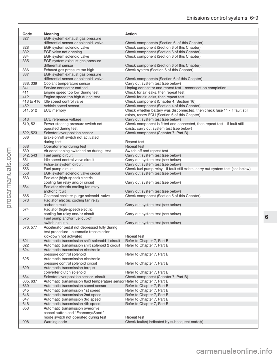
37Given overleaf are the possible codes,
their meanings, and where relevant, the action
to be taken as a result of a code being
displayed.
Emissions control systems 6•7
6
procarmanuals.com
Page 143 of 279
Code Meaning Action327 EGR system exhaust gas pressure
differential sensor or solenoid valve Check components (Section 6 of this Chapter)
328 EGR system solenoid valve Check component (Section 6 of this Chapter)
332 EGR valve not opening Check component (Section 6 of this Chapter)
334 EGR system solenoid valve Check component (Section 6 of this Chapter)335 EGR system exhaust gas pressure
differential sensor Check component (Section 6 of this Chapter)
336 Exhaust gas pressure too high Check system (Section 6 of this Chapter)337 EGR system exhaust gas pressure
differential sensor or solenoid valve Check components (Section 6 of this Chapter)
338, 339 Coolant temperature sensor Carry out system test (see below)
341 Service connector earthed Unplug connector and repeat test - reconnect on completion
411 Engine speed too low during test Check for air leaks, then repeat test
412 Engine speed too high during test Check for air leaks, then repeat test
413 to 416 Idle speed control valve Check component (Chapter 4, Section 16)
452 Vehicle speed sensor Check component (Section 4 of this Chapter)
511, 512 ECU memory Check whether battery was disconnected, then check fuse 11 - if fault still
exists, renew ECU (Section 6 of this Chapter)
513 ECU reference voltage Carry out system test (see below)
519, 521 Power steering pressure switch not Check component is fitted and connected, then repeat test - if fault still
operated during test exists, carry out system test (see below)
522, 523 Selector lever position sensor Check component (Chapter 7, Part B)
536 Brake on/off switch not activated
during test Repeat test
538 Operator error during test Repeat test
539 Air conditioning switched on during test Switch off and repeat test
542, 543 Fuel pump circuit Carry out system test (see below)
551 Idle speed control valve circuit Carry out system test (see below)
552 Pulse-air system circuit Carry out system test (see below)
556 Fuel pump circuit Check fuel pump relay - if fault still exists, carry out system test (see below)
558 EGR system solenoid valve circuit Carry out system test (see below)
563 Radiator (high-speed) electric
cooling fan relay and/or circuit Carry out system test (see below)564 Radiator electric cooling fan relay
and/or circuit Carry out system test (see below)
565 Charcoal canister-purge solenoid valve Check component (Section 5 of this Chapter)573 Radiator electric cooling fan relay
and/or circuit Carry out system test (see below)
574 Radiator (high-speed) electric
cooling fan relay and/or circuit Carry out system test (see below)575 Fuel pump and/or fuel cut-off
switch circuits Carry out system test (see below)
576, 577 Accelerator pedal not depressed fully during
test procedure - automatic transmission
kickdown not activated Repeat test
621 Automatic transmission shift solenoid 1 circuit Refer to Chapter 7, Part B
622 Automatic transmission shift solenoid 2 circuit Refer to Chapter 7, Part B
624 Automatic transmission electronic
pressure control solenoid Refer to Chapter 7, Part B
625 Automatic transmission electronic
pressure control solenoid circuit Refer to Chapter 7, Part B
629 Automatic transmission torque
converter clutch solenoid Refer to Chapter 7, Part B
634 Selector lever position sensor circuit Check component (Chapter 7, Part B)
635, 637 Automatic transmission fluid temperature sensor Refer to Chapter 7, Part B
639 Automatic transmission speed sensor Refer to Chapter 7, Part B
645 Automatic transmission 1st speed Refer to Chapter 7, Part B
646 Automatic transmission 2nd speed Refer to Chapter 7, Part B
647 Automatic transmission 3rd speed Refer to Chapter 7, Part B
648 Automatic transmission 4th speed Refer to Chapter 7, Part B
653 Automatic transmission overdrive
cancel button and “Economy/Sport”
mode switch not operated during test Repeat test
998 Warning code Check fault(s) indicated by subsequent code(s)
Emissions control systems 6•9
6
procarmanuals.com
Page 158 of 279
10•4 Suspension and steering systems
pressed-steel lower side arms. A tie-bar on
each side supports the rear suspension
knuckles. The coil springs are separate from
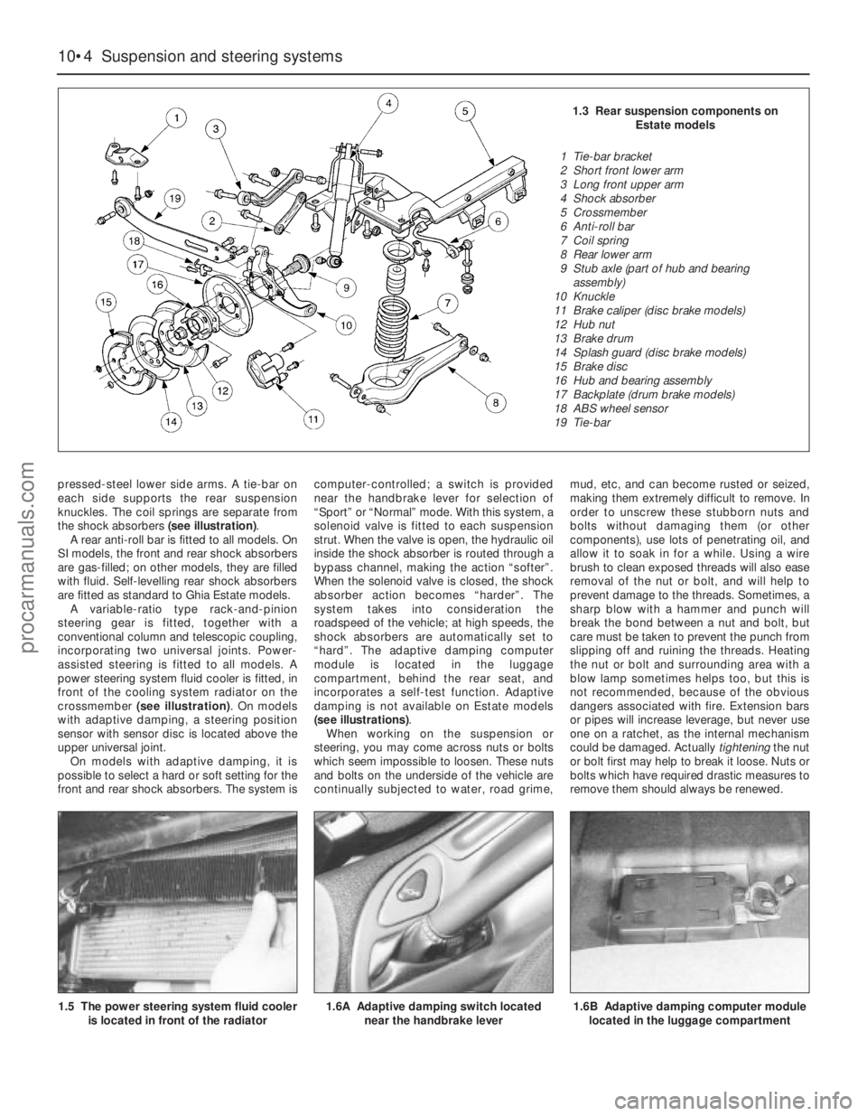
the shock absorbers (see illustration).
A rear anti-roll bar is fitted to all models. On
SI models, the front and rear shock absorbers
are gas-filled; on other models, they are filled
with fluid. Self-levelling rear shock absorbers
are fitted as standard to Ghia Estate models.
A variable-ratio type rack-and-pinion
steering gear is fitted, together with a
conventional column and telescopic coupling,
incorporating two universal joints. Power-
assisted steering is fitted to all models. A
power steering system fluid cooler is fitted, in
front of the cooling system radiator on the
crossmember (see illustration). On models
with adaptive damping, a steering position
sensor with sensor disc is located above the
upper universal joint.
On models with adaptive damping, it is
possible to select a hard or soft setting for the
front and rear shock absorbers. The system iscomputer-controlled; a switch is provided
near the handbrake lever for selection of
“Sport” or “Normal” mode. With this system, a
solenoid valve is fitted to each suspension
strut. When the valve is open, the hydraulic oil
inside the shock absorber is routed through a
bypass channel, making the action “softer”.
When the solenoid valve is closed, the shock
absorber action becomes “harder”. The
system takes into consideration the
roadspeed of the vehicle; at high speeds, the
shock absorbers are automatically set to
“hard”. The adaptive damping computer
module is located in the luggage
compartment, behind the rear seat, and
incorporates a self-test function. Adaptive
damping is not available on Estate models
(see illustrations).
When working on the suspension or
steering, you may come across nuts or bolts
which seem impossible to loosen. These nuts
and bolts on the underside of the vehicle are
continually subjected to water, road grime,mud, etc, and can become rusted or seized,
making them extremely difficult to remove. In
order to unscrew these stubborn nuts and
bolts without damaging them (or other
components), use lots of penetrating oil, and
allow it to soak in for a while. Using a wire
brush to clean exposed threads will also ease
removal of the nut or bolt, and will help to
prevent damage to the threads. Sometimes, a
sharp blow with a hammer and punch will
break the bond between a nut and bolt, but
care must be taken to prevent the punch from
slipping off and ruining the threads. Heating
the nut or bolt and surrounding area with a
blow lamp sometimes helps too, but this is
not recommended, because of the obvious
dangers associated with fire. Extension bars
or pipes will increase leverage, but never use
one on a ratchet, as the internal mechanism
could be damaged. Actually tighteningthe nut
or bolt first may help to break it loose. Nuts or
bolts which have required drastic measures to
remove them should always be renewed.
1.5 The power steering system fluid cooler
is located in front of the radiator
1.6A Adaptive damping switch located
near the handbrake lever1.6B Adaptive damping computer module
located in the luggage compartment
1.3 Rear suspension components on
Estate models
1 Tie-bar bracket
2 Short front lower arm
3 Long front upper arm
4 Shock absorber
5 Crossmember
6 Anti-roll bar
7 Coil spring
8 Rear lower arm
9 Stub axle (part of hub and bearing
assembly)
10 Knuckle
11 Brake caliper (disc brake models)
12 Hub nut
13 Brake drum
14 Splash guard (disc brake models)
15 Brake disc
16 Hub and bearing assembly
17 Backplate (drum brake models)
18 ABS wheel sensor
19 Tie-bar
procarmanuals.com
Page 208 of 279
Main light, auxiliary foglight and rear
foglight combination switch
Note:From July 1994 a rvised main light
switch was introduced; this was fitted as
standard in production. If the revised switch is
to be fitted to a pre-July 1994 model, an
adapter lead will also be required to prevent
electrical damage ocurring. Refer to your Ford
dealer for further information
9Disconnect the battery negative (earth) lead
(refer to Chapter 5, Section 1).
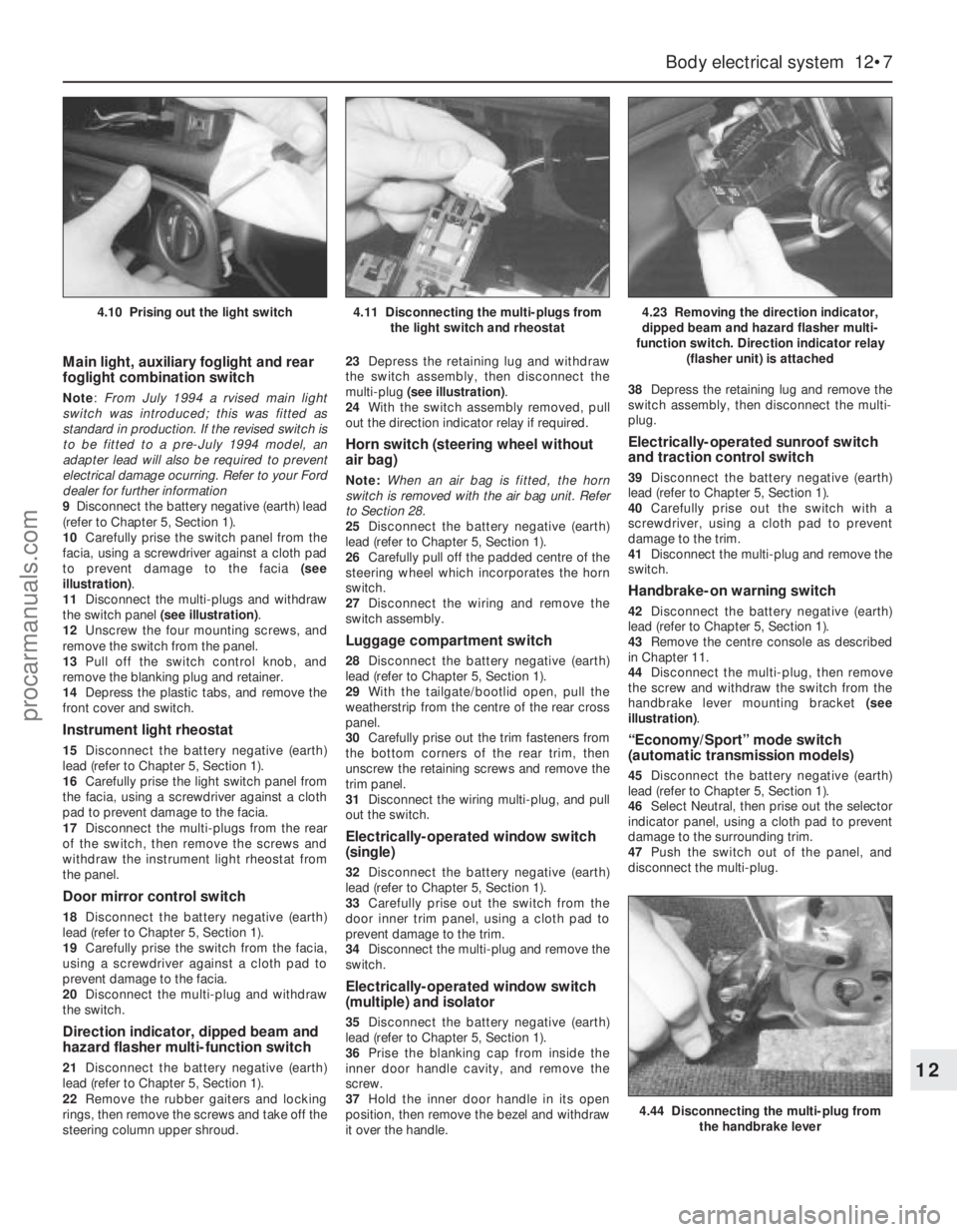
10Carefully prise the switch panel from the
facia, using a screwdriver against a cloth pad
to prevent damage to the facia (see
illustration).
11Disconnect the multi-plugs and withdraw
the switch panel (see illustration).
12Unscrew the four mounting screws, and
remove the switch from the panel.
13Pull off the switch control knob, and
remove the blanking plug and retainer.
14Depress the plastic tabs, and remove the
front cover and switch.
Instrument light rheostat
15Disconnect the battery negative (earth)
lead (refer to Chapter 5, Section 1).
16Carefully prise the light switch panel from
the facia, using a screwdriver against a cloth
pad to prevent damage to the facia.
17Disconnect the multi-plugs from the rear
of the switch, then remove the screws and
withdraw the instrument light rheostat from
the panel.
Door mirror control switch
18Disconnect the battery negative (earth)
lead (refer to Chapter 5, Section 1).
19Carefully prise the switch from the facia,
using a screwdriver against a cloth pad to
prevent damage to the facia.
20Disconnect the multi-plug and withdraw
the switch.
Direction indicator, dipped beam and
hazard flasher multi-function switch
21Disconnect the battery negative (earth)
lead (refer to Chapter 5, Section 1).
22Remove the rubber gaiters and locking
rings, then remove the screws and take off the
steering column upper shroud.23Depress the retaining lug and withdraw
the switch assembly, then disconnect the
multi-plug (see illustration).
24With the switch assembly removed, pull
out the direction indicator relay if required.
Horn switch (steering wheel without
air bag)
Note:When an air bag is fitted, the horn
switch is removed with the air bag unit. Refer
to Section 28.
25Disconnect the battery negative (earth)
lead (refer to Chapter 5, Section 1).
26Carefully pull off the padded centre of the
steering wheel which incorporates the horn
switch.
27Disconnect the wiring and remove the
switch assembly.
Luggage compartment switch
28Disconnect the battery negative (earth)
lead (refer to Chapter 5, Section 1).
29With the tailgate/bootlid open, pull the
weatherstrip from the centre of the rear cross
panel.
30Carefully prise out the trim fasteners from
the bottom corners of the rear trim, then
unscrew the retaining screws and remove the
trim panel.
31Disconnect the wiring multi-plug, and pull
out the switch.
Electrically-operated window switch
(single)
32Disconnect the battery negative (earth)
lead (refer to Chapter 5, Section 1).
33Carefully prise out the switch from the
door inner trim panel, using a cloth pad to
prevent damage to the trim.
34Disconnect the multi-plug and remove the
switch.
Electrically-operated window switch
(multiple) and isolator
35Disconnect the battery negative (earth)
lead (refer to Chapter 5, Section 1).
36Prise the blanking cap from inside the
inner door handle cavity, and remove the
screw.
37Hold the inner door handle in its open
position, then remove the bezel and withdraw
it over the handle.38Depress the retaining lug and remove the
switch assembly, then disconnect the multi-
plug.
Electrically-operated sunroof switch
and traction control switch
39Disconnect the battery negative (earth)
lead (refer to Chapter 5, Section 1).
40Carefully prise out the switch with a
screwdriver, using a cloth pad to prevent
damage to the trim.
41Disconnect the multi-plug and remove the
switch.
Handbrake-on warning switch
42Disconnect the battery negative (earth)
lead (refer to Chapter 5, Section 1).
43Remove the centre console as described
in Chapter 11.
44Disconnect the multi-plug, then remove
the screw and withdraw the switch from the
handbrake lever mounting bracket (see
illustration).
“Economy/Sport” mode switch
(automatic transmission models)
45Disconnect the battery negative (earth)
lead (refer to Chapter 5, Section 1).
46Select Neutral, then prise out the selector
indicator panel, using a cloth pad to prevent
damage to the surrounding trim.
47Push the switch out of the panel, and
disconnect the multi-plug.
Body electrical system 12•7
12
4.44 Disconnecting the multi-plug from
the handbrake lever
4.10 Prising out the light switch4.11 Disconnecting the multi-plugs from
the light switch and rheostat4.23 Removing the direction indicator,
dipped beam and hazard flasher multi-
function switch. Direction indicator relay
(flasher unit) is attached
procarmanuals.com
Page 222 of 279
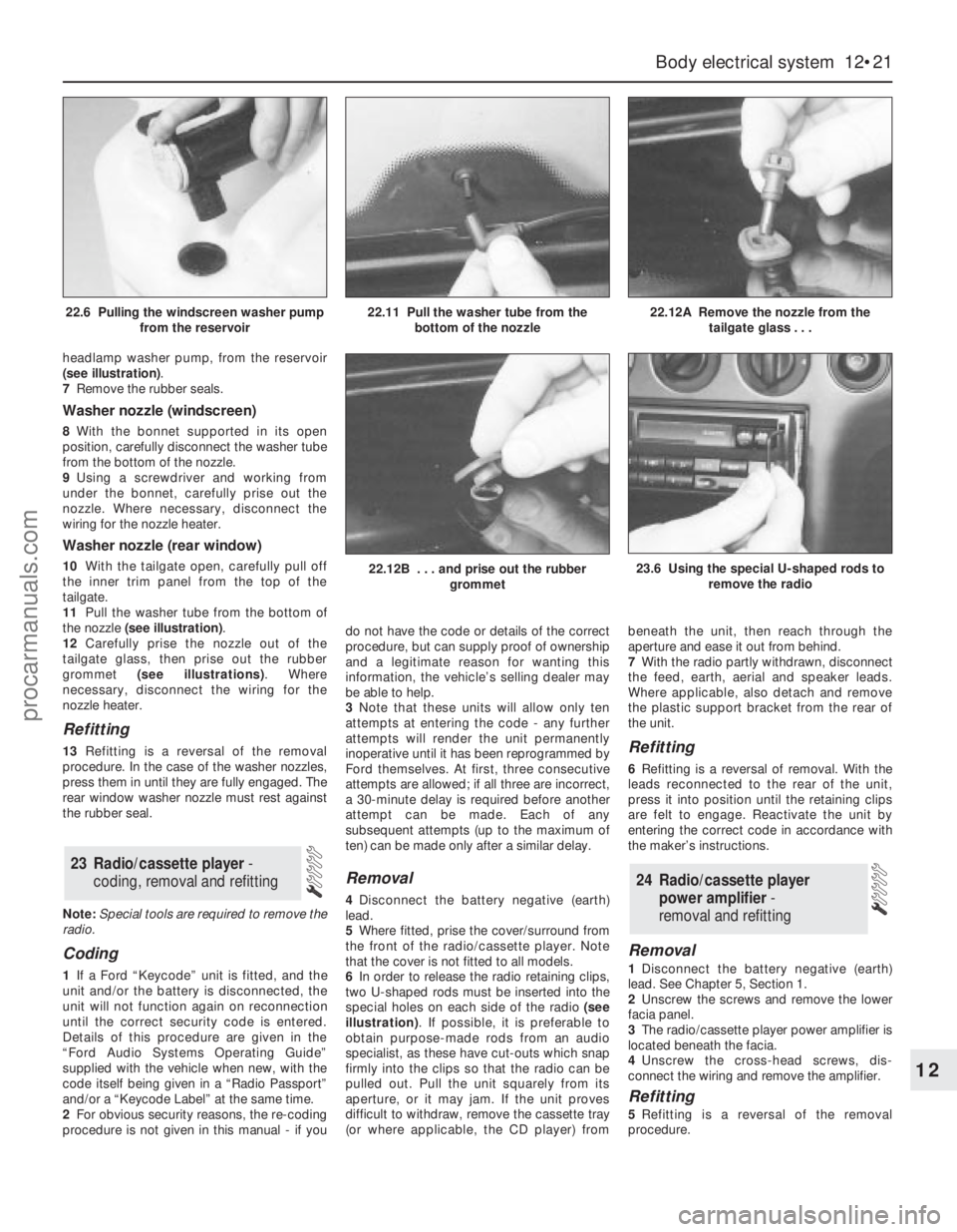
headlamp washer pump, from the reservoir
(see illustration).
7Remove the rubber seals.
Washer nozzle (windscreen)
8With the bonnet supported in its open
position, carefully disconnect the washer tube
from the bottom of the nozzle.
9Using a screwdriver and working from
under the bonnet, carefully prise out the
nozzle. Where necessary, disconnect the
wiring for the nozzle heater.
Washer nozzle (rear window)
10With the tailgate open, carefully pull off
the inner trim panel from the top of the
tailgate.
11Pull the washer tube from the bottom of
the nozzle (see illustration).
12Carefully prise the nozzle out of the
tailgate glass, then prise out the rubber
grommet (see illustrations). Where
necessary, disconnect the wiring for the
nozzle heater.
Refitting
13Refitting is a reversal of the removal
procedure. In the case of the washer nozzles,
press them in until they are fully engaged. The
rear window washer nozzle must rest against
the rubber seal.
Note:Special tools are required to remove the
radio.
Coding
1If a Ford “Keycode” unit is fitted, and the
unit and/or the battery is disconnected, the
unit will not function again on reconnection
until the correct security code is entered.
Details of this procedure are given in the
“Ford Audio Systems Operating Guide”
supplied with the vehicle when new, with the
code itself being given in a “Radio Passport”
and/or a “Keycode Label” at the same time.
2For obvious security reasons, the re-coding
procedure is not given in this manual - if youdo not have the code or details of the correct
procedure, but can supply proof of ownership
and a legitimate reason for wanting this
information, the vehicle’s selling dealer may
be able to help.
3Note that these units will allow only ten
attempts at entering the code - any further
attempts will render the unit permanently
inoperative until it has been reprogrammed by
Ford themselves. At first, three consecutive
attempts are allowed; if all three are incorrect,
a 30-minute delay is required before another
attempt can be made. Each of any
subsequent attempts (up to the maximum of
ten) can be made only after a similar delay.
Removal
4Disconnect the battery negative (earth)
lead.
5Where fitted, prise the cover/surround from
the front of the radio/cassette player. Note
that the cover is not fitted to all models.
6In order to release the radio retaining clips,
two U-shaped rods must be inserted into the
special holes on each side of the radio (see
illustration). If possible, it is preferable to
obtain purpose-made rods from an audio
specialist, as these have cut-outs which snap
firmly into the clips so that the radio can be
pulled out. Pull the unit squarely from its
aperture, or it may jam. If the unit proves
difficult to withdraw, remove the cassette tray
(or where applicable, the CD player) frombeneath the unit, then reach through the
aperture and ease it out from behind.
7With the radio partly withdrawn, disconnect
the feed, earth, aerial and speaker leads.
Where applicable, also detach and remove
the plastic support bracket from the rear of
the unit.
Refitting
6Refitting is a reversal of removal. With the
leads reconnected to the rear of the unit,
press it into position until the retaining clips
are felt to engage. Reactivate the unit by
entering the correct code in accordance with
the maker’s instructions.
Removal
1Disconnect the battery negative (earth)
lead. See Chapter 5, Section 1.
2Unscrew the screws and remove the lower
facia panel.
3The radio/cassette player power amplifier is
located beneath the facia.
4Unscrew the cross-head screws, dis-
connect the wiring and remove the amplifier.
Refitting
5Refitting is a reversal of the removal
procedure.
24 Radio/cassette player
power amplifier -
removal and refitting
23 Radio/cassette player -
coding, removal and refitting
Body electrical system 12•21
12
22.12B . . . and prise out the rubber
grommet23.6 Using the special U-shaped rods to
remove the radio
22.6 Pulling the windscreen washer pump
from the reservoir22.11 Pull the washer tube from the
bottom of the nozzle22.12A Remove the nozzle from the
tailgate glass . . .
procarmanuals.com
Page 277 of 279
REF•18Index
E
Earth fault - 12•4
Economy/Sport mode switch - 12•7
ECU (Electronic Control Unit) - 6•10, 6•11,
6•12
EGR exhaust gas pressure differential
sensor - 6•16
EGR system - 6•15, 6•16
Electric shock - 0•5
Electric windows fault - REF•12
Electrical system - 0•8, 1•11, 1•20
Electrical system fault - REF•12
Electrically-operated windows - 12•7
Electrolyte - 1•8
Electronic control system - 4•9, 6•2
Emblems - 11•17
Emission checks - 0•10
Emissions control systems - 6•1
Engine compartment light - 12•11
Engine electrical systems- 5•1et seq
Engine fault finding - REF•7, REF•8, REF•10
Engine management system - 4•8, 4•9
Engine oil - 1•2, 1•6, 1•16
Engine oil level sensor - 12•18
Engine removal and general engine
overhaul procedures- 2B•1et seq
Environmental considerations - REF•4
Evaporative emissions control (EVAP)
system - 6•14
Evaporator - 3•9
Exhaust gas pressure differential sensor -
6•11, 6•12, 6•13
Exhaust Gas Recirculation (EGR) system -
6•15, 6•16
Exhaust manifold - 2A•8
Exhaust system - 0•9, 0•10, 1•18, 4•12,
REF•9
Expansion tank - 3•5, 3•6
FFacia - 11•21, 11•23
Fan(s) - 3•4, 12•11
Fault code read-out - 6•6
Fault finding- REF•6et seq
Fault finding - automatic transmission -
7B•1
Fault finding - electrical system - 12•4
Filling - 11•3
Fire - 0•5
Fluid level checks - 1•6
Flywheel - 2A•24
Foglight - 12•7, 12•9, 12•13
Foglight warning indicator - 12•11
Fuel and exhaust systems- 0•10, 4•1et
seq
Fuel and exhaust system fault finding -
REF•9
Fuel consumption high - REF•9
Fuel cut-off switch - 4•8
Fuel filter - 1•26
Fuel gauge - 4•6
Fuel gauge fault - REF•12
Fuel hoses - 1•15
Fuel injection system - 4•8, 4•9
Fuel injectors - 4•10
Fuel lines - 1•19, 4•2
Fuel odour - REF•9Fuel pressure check - 4•5
Fuel pressure regulator - 4•11
Fuel pump - 4•5, 4•6
Fuel rail - 4•10
Fuel system - 4•2
Fuel tank - 4•7, 4•8
Fume or gas intoxication - 0•5
Fumes from exhaust system - REF•9
Fuses - 12•5
G
Gaiters - 1•18, 8•7, 8•9, 10•21
Gashes in bodywork - 11•3
Gaskets - REF•4
Gear lever - 7A•2
Gear selection problems - REF•9, REF•10
Gearbox oil - 1•2
Gearchange linkage - 7A•2
Gearchange selector shaft - 7A•3
Glossary of technical terms - REF•13
Glovebox - 11•22
Glovebox light - 12•11
Grab handle - 11•20
H
Handbrake - 0•7, 9•16, 12•7
Handles - 11•10, 11•11, 11•12, 11•13,
12•11
Hazard flashers - 12•7, 12•11
HC emissions - 0•10
Headlight - 1•8, 12•7, 12•8, 12•12, 12•13
Heated rear window - 12•8
Heated seat - 12•8
Heated windscreen - 12•8
Heater - 3•2, 3•7, 3•8, 12•11, 12•12
Horn - 12•7, 12•15
Horn fault - REF•12
Hoses - 1•14, 3•2, 9•11
HT leads - 1•24
Hub and bearings - 10•5, 10•9, 10•14
Hydraulic fluid - 1•2
Hydraulic pipes and hoses - 9•11
Hydraulic system - 9•12
Hydraulic tappets - 2A•14
Hydrofluoric acid - 0•5
I
Idle speed - 4•9, 4•11, 6•10
Idle-increase solenoid valve - 4•12
Ignition coil - 5•3
Ignition module - 5•4
Ignition switch - 12•6
Ignition system - 5•3
Ignition timing - 5•4, 6•10
In-car engine repair procedures- 2A•1et
seq
Indicators - 12•7, 12•9, 12•12
Information sensors - 6•10
Inlet manifold - 2A•7
Instrument panel - 12•7, 12•11, 12•14
Instruments - 1•20
Instruments fault - REF•12
Intake air temperature sensor - 6•11, 6•13
Introduction to the Ford Mondeo - 0•4
J
Jacking - 0•11
Joint mating faces - REF•4
Jump starting - 0•12
K
Knuckle - 10•5, 10•10, 10•14
L
Leaks - 0•13, 1•14, REF•9
Light units - 12•12
Lights - 12•7, 12•11
Lights inoperative - REF•12
Locknuts, locktabs and washers - REF•4
Locks - 11•6, 11•10, 11•12, 11•13, 11•15,
11•16, 11•17, 12•6, REF•12
Low air temperature warning sender unit -
12•18
Low coolant warning switch - 12•18
Low washer fluid switch - 12•18
Lower suspension arm - 10•8, 10•9, 10•13,
10•16
Lubrication system - 2A•4
Luggage compartment switch - 12•7
M
Main bearings - 2B•18, 2B•20
Maintenance- Also see Routine
maintenance
Maintenance - bodywork and underframe -
11•2
Maintenance - upholstery and carpets -
11•3
Manifolds - 2A•7, 2A•8
Manual transmission- 1•17, 2A•24, 2B•3,
2B•4, 7A•1et seq
Manual transmission fault finding - REF•9
Manual transmission oil - 1•2
Master cylinder - 9•10
Mirrors - 0•7, 11•14, 12•7
Misfire - REF•7, REF•8
Mixture - 0•10, 4•9
MOT test checks- 0•7et seq
Mountings - 2A•24, 7A•7, 7B•5
N
Number plate light - 12•10, 12•13
O
Oil (transmission) - 1•2
Oil (engine) - 1•2, 1•6, 1•16
Oil cooler - 2A•22
Oil level sensor - 2A•22, 12•18
Oil pressure warning light illuminated -
REF•8
procarmanuals.com
Page 279 of 279
REF•20
Almost ever y car you’ve ever loved, loathed or desired is gathered under one roof at the Haynes Motor
Museum. Over 300 immaculately presented cars and motorbikes represent ever y aspect of our motoring
heritage, from elegant reminders of bygone days, such as the superb Model J Duesenberg to curiosities like
the bug-eyed BMW Isetta. There are also many old friends and flames. Perhaps you remember the 1959 Ford
Popular that you did your courting in? The magnificent ‘Red Collection’ is a spectacle of classic sports cars
including AC, Alfa Romeo, Austin Healey, Ferrari, Lamborghini, Maserati, MG, Riley, Porsche and Triumph.
A Perfect Day Out
Each and ever y vehicle at the Haynes Motor Museum has played its part in the histor y and culture of
Motoring. Today, they make a wonderful spectacle and a great day out for all the family. Bring the kids, bring
Mum and Dad, but above all bring your camera to capture those golden memories for ever. You will also find
an impressive array of motoring memorabilia, a comfortable 70 seat video cinema and one of the most
extensive transport book shops in Britain. The Pit Stop Cafe serves ever ything from a cup of tea to
wholesome, home-made meals or, if you prefer, you can enjoy the large picnic area nestled in the beautiful
rural surroundings of Somerset.
The Museum is situated on the A359 Yeovil to Frome road at Sparkford, just off the A303 in Somerset. It is about 40 miles south of Bristol, and
25 minutes drive from the M5 intersection at Taunton.
Open 9.30am - 5.30pm (10.00am - 4.00pm Winter) 7 days a week, except Christmas Day, Boxing Day and New Years Day
Special rates available for schools, coach parties and outings Charitable Trust No. 292048
>John Haynes O.B.E.,
Founder and
Chairman of the
museum at the wheel
of a Haynes Light 12.
car next to a 1934
Riley Sports.
Only eight of these
magnificent cars were
ever built – this is the
only example to be found
outside the United
States of America
Preserving Our Motoring Heritage
procarmanuals.com