1993 FORD MONDEO fuel consumption
[x] Cancel search: fuel consumptionPage 14 of 279
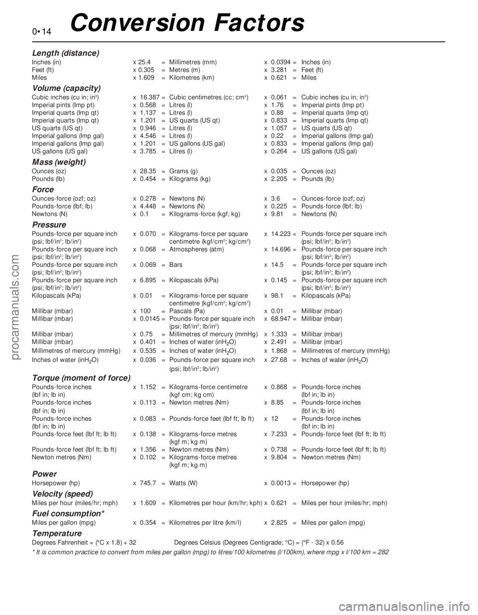
0•14Conversion Factors
Length (distance)
Inches (in) x 25.4 = Millimetres (mm) x 0.0394 = Inches (in)
Feet (ft) x 0.305 = Metres (m) x 3.281 = Feet (ft)
Miles x 1.609 = Kilometres (km) x 0.621 = Miles
Volume (capacity)
Cubic inches (cu in; in3) x 16.387 = Cubic centimetres (cc; cm3) x 0.061 = Cubic inches (cu in; in3)
Imperial pints (Imp pt) x 0.568 = Litres (l) x 1.76 = Imperial pints (Imp pt)
Imperial quarts (Imp qt) x 1.137 = Litres (l) x 0.88 = Imperial quarts (Imp qt)
Imperial quarts (Imp qt) x 1.201 = US quarts (US qt) x 0.833 = Imperial quarts (Imp qt)
US quarts (US qt) x 0.946 = Litres (l) x 1.057 = US quarts (US qt)
Imperial gallons (Imp gal) x 4.546 = Litres (l) x 0.22 = Imperial gallons (Imp gal)
Imperial gallons (Imp gal) x 1.201 = US gallons (US gal) x 0.833 = Imperial gallons (Imp gal)
US gallons (US gal) x 3.785 = Litres (l) x 0.264 = US gallons (US gal)
Mass (weight)
Ounces (oz) x 28.35 = Grams (g) x 0.035 = Ounces (oz)
Pounds (lb) x 0.454 = Kilograms (kg) x 2.205 = Pounds (lb)
Force
Ounces-force (ozf; oz) x 0.278 = Newtons (N) x 3.6 = Ounces-force (ozf; oz)
Pounds-force (lbf; lb) x 4.448 = Newtons (N) x 0.225 = Pounds-force (lbf; lb)
Newtons (N) x 0.1 = Kilograms-force (kgf; kg) x 9.81 = Newtons (N)
Pressure
Pounds-force per square inch x 0.070 = Kilograms-force per square x 14.223 = Pounds-force per square inch
(psi; lbf/in2; lb/in2) centimetre (kgf/cm2; kg/cm2) (psi; lbf/in2; lb/in2)
Pounds-force per square inch x 0.068 = Atmospheres (atm) x 14.696 = Pounds-force per square inch
(psi; lbf/in
2; lb/in2)(psi; lbf/in2; lb/in2)
Pounds-force per square inch x 0.069 = Bars x 14.5 = Pounds-force per square inch
(psi; lbf/in
2; lb/in2)(psi; lbf/in2; lb/in2)
Pounds-force per square inch x 6.895 = Kilopascals (kPa) x 0.145 = Pounds-force per square inch
(psi; lbf/in
2; lb/in2)(psi; lbf/in2; lb/in2)
Kilopascals (kPa) x 0.01 = Kilograms-force per square x 98.1 = Kilopascals (kPa)
centimetre (kgf/cm
2; kg/cm2)
Millibar (mbar) x 100 = Pascals (Pa) x 0.01 = Millibar (mbar)
Millibar (mbar) x 0.0145 = Pounds-force per square inch x 68.947 = Millibar (mbar)
(psi; lbf/in
2; lb/in2)
Millibar (mbar) x 0.75 = Millimetres of mercury (mmHg) x 1.333 = Millibar (mbar)
Millibar (mbar) x 0.401 = Inches of water (inH
2O) x 2.491 = Millibar (mbar)
Millimetres of mercury (mmHg) x 0.535 = Inches of water (inH
2O) x 1.868 = Millimetres of mercury (mmHg)
Inches of water (inH
2O) x 0.036 = Pounds-force per square inch x 27.68 = Inches of water (inH2O)
(psi; lbf/in2; lb/in2)
Torque (moment of force)
Pounds-force inches x 1.152 = Kilograms-force centimetre x 0.868 = Pounds-force inches
(lbf in; lb in) (kgf cm; kg cm) (lbf in; lb in)
Pounds-force inches x 0.113 = Newton metres (Nm) x 8.85 = Pounds-force inches
(lbf in; lb in)(lbf in; lb in)
Pounds-force inches x 0.083 = Pounds-force feet (lbf ft; lb ft) x 12 = Pounds-force inches
(lbf in; lb in)(lbf in; lb in)
Pounds-force feet (lbf ft; lb ft) x 0.138 = Kilograms-force metres x 7.233 = Pounds-force feet (lbf ft; lb ft)
(kgf m; kg m)
Pounds-force feet (lbf ft; lb ft) x 1.356 = Newton metres (Nm) x 0.738 = Pounds-force feet (lbf ft; lb ft)
Newton metres (Nm) x 0.102 = Kilograms-force metres x 9.804 = Newton metres (Nm)
(kgf m; kg m)
Power
Horsepower (hp) x 745.7 = Watts (W) x 0.0013 = Horsepower (hp)
Velocity (speed)
Miles per hour (miles/hr; mph) x 1.609 = Kilometres per hour (km/hr; kph) x 0.621 = Miles per hour (miles/hr; mph)
Fuel consumption*
Miles per gallon (mpg) x 0.354 = Kilometres per litre (km/l) x 2.825 = Miles per gallon (mpg)
Temperature
Degrees Fahrenheit = (°C x 1.8) + 32 Degrees Celsius (Degrees Centigrade; °C) = (°F - 32) x 0.56
* It is common practice to convert from miles per gallon (mpg) to litres/100 kilometres (l/100km), where mpg x l/100 km = 282
procarmanuals.com
Page 45 of 279
The cylinder head is provided with two oil
galleries, one on the inlet side and one on the
exhaust, to ensure constant oil supply to the
camshaft bearings and hydraulic tappets. A
retaining valve (inserted into the cylinder
head’s top surface, in the middle, on the inlet
side) prevents these galleries from being
drained when the engine is switched off. The
valve incorporates a ventilation hole in its
upper end, to allow air bubbles to escape
from the system when the engine is restarted.
While the crankshaft and camshaft
bearings and the hydraulic tappets receive a
pressurised supply, the camshaft lobes and
valves are lubricated by splash, as are all
other engine components.
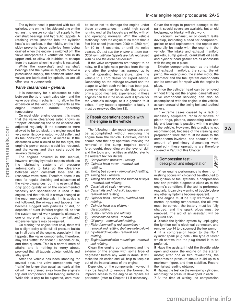
Valve clearances - general
It is necessary for a clearance to exist
between the tip of each valve stem and the
valve operating mechanism, to allow for the
expansion of the various components as the
engine reaches normal operating
temperature.
On most older engine designs, this meant
that the valve clearances (also known as
“tappet” clearances) had to be checked and
adjusted regularly. If the clearances were
allowed to be too slack, the engine would be
very noisy, its power output would suffer, and
its fuel consumption would increase. If the
clearances were allowed to be too tight, the
engine’s power output would be reduced,
and the valves and their seats could be
severely damaged.
The engines covered in this manual,
however, employ hydraulic tappets which use
the lubricating system’s oil pressure
automatically to take up the clearance
between each camshaft lobe and its
respective valve stem. Therefore, there is no
need for regular checking and adjustment of
the valve clearances, but it is essential that
onlygood-quality oil of the recommended
viscosity and specification is used in the
engine, and that this oil is always changed at
the recommended intervals. If this advice is
not followed, the oilways and tappets may
become clogged with particles of dirt, or
deposits of burnt (inferior) engine oil, so that
the system cannot work properly; ultimately,
one or more of the tappets may fail, and
expensive repairs may be required.
On starting the engine from cold, there will
be a slight delay while full oil pressure builds
up in all parts of the engine, especially in the
tappets; the valve components, therefore,
may well “rattle” for about 10 seconds or so,
and then quieten. This is a normal state of
affairs, and is nothing to worry about,
provided that all tappets quieten quickly and
stay quiet.
After the vehicle has been standing for
several days, the valve components may
“rattle” for longer than usual, as nearly all the
oil will have drained away from the engine’s
top end components and bearing surfaces.
While this is only to be expected, care mustbe taken not to damage the engine under
these circumstances - avoid high speed
running until all the tappets are refilled with oil
and operating normally. With the vehicle
stationary, hold the engine at no more than a
fast idle speed (maximum 2000 to 2500 rpm)
for 10 to 15 seconds, or until the noise
ceases. Do not run the engine at more than
3000 rpm until the tappets are fully recharged
with oil and the noise has ceased.
If the valve components are thought to be
noisy, or if a light rattle persists from the top
end after the engine has warmed up to
normal operating temperature, take the
vehicle to a Ford dealer for expert advice.
Depending on the mileage covered and the
usage to which each vehicle has been put,
some vehicles may be noisier than others;
only a good mechanic experienced in these
engines can tell if the noise level is typical for
the vehicle’s mileage, or if a genuine fault
exists. If any tappet’s operation is faulty, it
must be renewed (Section 13).
The following major repair operations can
be accomplished without removing the
engine from the vehicle. However, owners
should note that any operation involving the
removal of the sump requires careful
forethought, depending on the level of skill
and the tools and facilities available; refer to
the relevant text for details.
(a) Compression pressure - testing.
(b) Cylinder head cover - removal and
refitting.
(c) Timing belt covers - removal and refitting.
(d) Timing belt - renewal.
(e) Timing belt tensioner and toothed pulleys
- removal and refitting.
(f) Camshaft oil seals - renewal.
(g) Camshafts and hydraulic tappets -
removal and refitting.
(h) Cylinder head - removal, overhaul and
refitting.
(i) Cylinder head and pistons -
decarbonising.
(j) Sump - removal and refitting.
(k) Crankshaft oil seals - renewal.
(l) Oil pump - removal and refitting.
(m) Piston/connecting rod assemblies -
removal and refitting (but see note below).
(n) Flywheel/driveplate - removal and
refitting.
(o) Engine/transmission mountings - removal
and refitting.
Clean the engine compartment and the
exterior of the engine with some type of
degreaser before any work is done. It will
make the job easier, and will help to keep dirt
out of the internal areas of the engine.
Depending on the components involved, it
may be helpful to remove the bonnet, to
improve access to the engine as repairs are
performed (refer to Chapter 11 if necessary).Cover the wings to prevent damage to the
paint; special covers are available, but an old
bedspread or blanket will also work.
If vacuum, exhaust, oil or coolant leaks
develop, indicating a need for component/
gasket or seal replacement, the repairs can
generally be made with the engine in the
vehicle. The intake and exhaust manifold
gaskets, sump gasket, crankshaft oil seals
and cylinder head gasket are all accessible
with the engine in place.
Exterior components such as the intake
and exhaust manifolds, the sump, the oil
pump, the water pump, the starter motor, the
alternator and the fuel system components
can be removed for repair with the engine in
place.
Since the cylinder head can be removed
without lifting out the engine, camshaft and
valve component servicing can also be
accomplished with the engine in the vehicle,
as can renewal of the timing belt and toothed
pulleys.
In extreme cases caused by a lack of
necessary equipment, repair or renewal of
piston rings, pistons, connecting rods and
big-end bearings is possible with the engine
in the vehicle. However, this practice is not
recommended, because of the cleaning and
preparation work that must be done to the
components involved, and because of the
amount of preliminary dismantling work
required - these operations are therefore
covered in Part B of this Chapter.
1When engine performance is down, or if
misfiring occurs which cannot be attributed to
the ignition or fuel systems, a compression
test can provide diagnostic clues as to the
engine’s condition. If the test is performed
regularly, it can give warning of trouble before
any other symptoms become apparent.
2The engine must be fully warmed-up to
normal operating temperature, the oil level
must be correct, the battery must be fully
charged, and the spark plugs must be
removed. The aid of an assistant will be
required also.
3Disable the ignition system by unplugging
the ignition coil’s electrical connector, and
remove fuse 14 to disconnect the fuel pump.
4Fit a compression tester to the No 1
cylinder spark plug hole - the type of tester
which screws into the plug thread is to be
preferred.
5Have the assistant hold the throttle wide
open and crank the engine on the starter
motor; after one or two revolutions, the
compression pressure should build up to a
maximum figure, and then stabilise. Record
the highest reading obtained.
6Repeat the test on the remaining cylinders,
recording the pressure developed in each.
7At the time of writing, no compression
3 Compression test -
description and interpretation
2 Repair operations possible with
the engine in the vehicle
In-car engine repair procedures 2A•5
2A
procarmanuals.com
Page 69 of 279
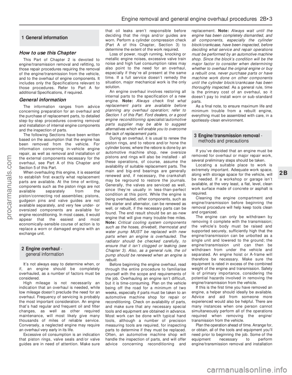
How to use this Chapter
This Part of Chapter 2 is devoted to
engine/transmission removal and refitting, to
those repair procedures requiring the removal
of the engine/transmission from the vehicle,
and to the overhaul of engine components. It
includes only the Specifications relevant to
those procedures. Refer to Part A for
additional Specifications, if required.
General information
The information ranges from advice
concerning preparation for an overhaul and
the purchase of replacement parts, to detailed
step-by-step procedures covering removal
and installation of internal engine components
and the inspection of parts.
The following Sections have been written
based on the assumption that the engine has
been removed from the vehicle. For
information concerning in-vehicle engine
repair, as well as removal and installation of
the external components necessary for the
overhaul, see Part A of this Chapter and
Section 5 of this Part.
When overhauling this engine, it is essential
to establish first exactly what replacement
parts are available. At the time of writing,
components such as the piston rings are not
available separately from the
piston/connecting rod assemblies; pistons,
gudgeon pins and valve guides are not
available separately, and very few under- or
oversized components are available for
engine reconditioning. In most cases, it would
appear that the easiest and most
economically-sensible course of action is to
replace a worn or damaged engine with an
exchange unit.
It’s not always easy to determine when, or
if, an engine should be completely
overhauled, as a number of factors must be
considered.
High mileage is not necessarily an
indication that an overhaul is needed, while
low mileage doesn’t preclude the need for an
overhaul. Frequency of servicing is probably
the most important consideration. An engine
that’s had regular and frequent oil and filter
changes, as well as other required
maintenance, will most likely give many
thousands of miles of reliable service.
Conversely, a neglected engine may require
an overhaul very early in its life.
Excessive oil consumption is an indication
that piston rings, valve seals and/or valve
guides are in need of attention. Make surethat oil leaks aren’t responsible before
deciding that the rings and/or guides are
worn. Perform a cylinder compression check
(Part A of this Chapter, Section 3) to
determine the extent of the work required.
Loss of power, rough running, knocking or
metallic engine noises, excessive valve train
noise and high fuel consumption rates may
also point to the need for an overhaul,
especially if they’re all present at the same
time. If a full service doesn’t remedy the
situation, major mechanical work is the only
solution.
An engine overhaul involves restoring all
internal parts to the specification of a new
engine. Note:Always check first what
replacement parts are available before
planning any overhaul operation; refer to
Section 1 of this Part. Ford dealers, or a good
engine reconditioning specialist/automotive
parts supplier may be able to suggest
alternatives which will enable you to overcome
the lack of replacement parts.
During an overhaul, it is usual to renew the
piston rings, and to rebore and/or hone the
cylinder bores; where the rebore is done by an
automotive machine shop, new oversize
pistons and rings will also be installed - all
these operations, of course, assume the
availability of suitable replacement parts. The
main and big-end bearings are generally
renewed and, if necessary, the crankshaft
may be reground to restore the journals.
Generally, the valves are serviced as well,
since they’re usually in less-than-perfect
condition at this point. While the engine is
being overhauled, other components, such as
the starter and alternator, can be renewed as
well, or rebuilt, if the necessary parts can be
found. The end result should be an as-new
engine that will give many trouble-free miles.
Note:Critical cooling system components
such as the hoses, drivebelt, thermostat and
water pump MUST be replaced with new
parts when an engine is overhauled. The
radiator should be checked carefully, to
ensure that it isn’t clogged or leaking (see
Chapter 3). Also, as a general rule, the oil
pump should be renewed when an engine is
rebuilt.
Before beginning the engine overhaul, read
through the entire procedure to familiarise
yourself with the scope and requirements of
the job. Overhauling an engine isn’t difficult,
but it is time-consuming. Plan on the vehicle
being off the road for a minimum of two
weeks, especially if parts must be taken to an
automotive machine shop for repair or
reconditioning. Check on availability of parts,
and make sure that any necessary special
tools and equipment are obtained in advance.
Most work can be done with typical hand
tools, although a number of precision
measuring tools are required, for inspecting
parts to determine if they must be replaced.
Often, an automotive machine shop will
handle the inspection of parts, and will offer
advice concerning reconditioning andreplacement. Note:Always wait until the
engine has been completely dismantled, and
all components, especially the cylinder
block/crankcase, have been inspected, before
deciding what service and repair operations
must be performed by an automotive machine
shop. Since the block’s condition will be the
major factor to consider when determining
whether to overhaul the original engine or buy
a rebuilt one, never purchase parts or have
machine work done on other components
until the cylinder block/crankcase has been
thoroughly inspected.As a general rule, time
is the primary cost of an overhaul, so it
doesn’t pay to install worn or sub-standard
parts.
As a final note, to ensure maximum life and
minimum trouble from a rebuilt engine,
everything must be assembled with care, in a
spotlessly-clean environment.
If you’ve decided that an engine must be
removed for overhaul or major repair work,
several preliminary steps should be taken.
Locating a suitable place to work is
extremely important. Adequate work space,
along with storage space for the vehicle, will
be needed. If a workshop or garage isn’t
available, at the very least, a flat, level, clean
work surface made of concrete or asphalt is
required.
Cleaning the engine compartment and
engine/transmission before beginning the
removal procedure will help keep tools clean
and organized.
The engine can only be withdrawn by
removing it complete with the transmission;
the vehicle’s body must be raised and
supported securely, sufficiently high that the
engine/transmission can be unbolted as a
single unit and lowered to the ground; the
engine/transmission unit can then be
withdrawn from under the vehicle and
separated. An engine hoist or A-frame will
therefore be necessary. Make sure the
equipment is rated in excess of the combined
weight of the engine and transmission. Safety
is of primary importance, considering the
potential hazards involved in removing the
engine/transmission from the vehicle.
If this is the first time you have removed an
engine, a helper should ideally be available.
Advice and aid from someone more
experienced would also be helpful. There are
many instances when one person cannot
simultaneously perform all of the operations
required when removing the engine/
transmission from the vehicle.
Plan the operation ahead of time. Arrange for,
or obtain, all of the tools and equipment you’ll
need prior to beginning the job. Some of the
equipment necessary to perform
engine/transmission removal and installation
3 Engine/transmission removal -
methods and precautions
2 Engine overhaul -
general information
1 General information
Engine removal and general engine overhaul procedures 2B•3
2B
procarmanuals.com
Page 107 of 279
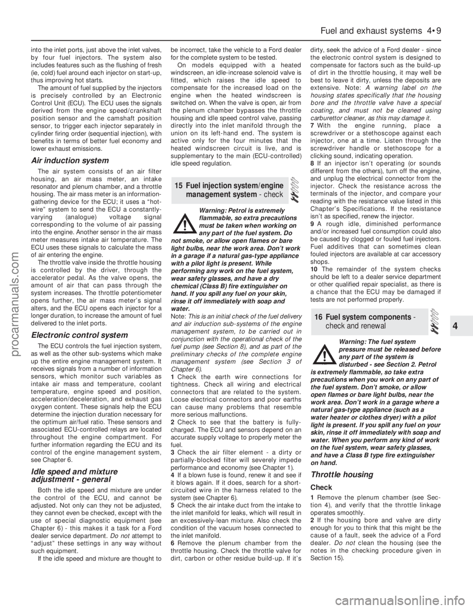
into the inlet ports, just above the inlet valves,
by four fuel injectors. The system also
includes features such as the flushing of fresh
(ie, cold) fuel around each injector on start-up,
thus improving hot starts.
The amount of fuel supplied by the injectors
is precisely controlled by an Electronic
Control Unit (ECU). The ECU uses the signals
derived from the engine speed/crankshaft
position sensor and the camshaft position
sensor, to trigger each injector separately in
cylinder firing order (sequential injection), with
benefits in terms of better fuel economy and
lower exhaust emissions.
Air induction system
The air system consists of an air filter
housing, an air mass meter, an intake
resonator and plenum chamber, and a throttle
housing. The air mass meter is an information-
gathering device for the ECU; it uses a “hot-
wire” system to send the ECU a constantly-
varying (analogue) voltage signal
corresponding to the volume of air passing
into the engine. Another sensor in the air mass
meter measures intake air temperature. The
ECU uses these signals to calculate the mass
of air entering the engine.
The throttle valve inside the throttle housing
is controlled by the driver, through the
accelerator pedal. As the valve opens, the
amount of air that can pass through the
system increases. The throttle potentiometer
opens further, the air mass meter’s signal
alters, and the ECU opens each injector for a
longer duration, to increase the amount of fuel
delivered to the inlet ports.
Electronic control system
The ECU controls the fuel injection system,
as well as the other sub-systems which make
up the entire engine management system. It
receives signals from a number of information
sensors, which monitor such variables as
intake air mass and temperature, coolant
temperature, engine speed and position,
acceleration/deceleration, and exhaust gas
oxygen content. These signals help the ECU
determine the injection duration necessary for
the optimum air/fuel ratio. These sensors and
associated ECU-controlled relays are located
throughout the engine compartment. For
further information regarding the ECU and its
control of the engine management system,
see Chapter 6.
Idle speed and mixture
adjustment - general
Both the idle speed and mixture are under
the control of the ECU, and cannot be
adjusted. Not only can they not be adjusted,
they cannot even be checked, except with the
use of special diagnostic equipment (see
Chapter 6) - this makes it a task for a Ford
dealer service department. Do notattempt to
“adjust” these settings in any way without
such equipment.
If the idle speed and mixture are thought tobe incorrect, take the vehicle to a Ford dealer
for the complete system to be tested.
On models equipped with a heated
windscreen, an idle-increase solenoid valve is
fitted, which raises the idle speed to
compensate for the increased load on the
engine when the heated windscreen is
switched on. When the valve is open, air from
the plenum chamber bypasses the throttle
housing and idle speed control valve, passing
directly into the inlet manifold through the
union on its left-hand end. The system is
active only for the four minutes that the
heated windscreen circuit is live, and is
supplementary to the main (ECU-controlled)
idle speed regulation.
Warning: Petrol is extremely
flammable, so extra precautions
must be taken when working on
any part of the fuel system. Do
not smoke, or allow open flames or bare
light bulbs, near the work area. Don’t work
in a garage if a natural gas-type appliance
with a pilot light is present. While
performing any work on the fuel system,
wear safety glasses, and have a dry
chemical (Class B) fire extinguisher on
hand. If you spill any fuel on your skin,
rinse it off immediately with soap and
water.
Note: This is an initial check of the fuel delivery
and air induction sub-systems of the engine
management system, to be carried out in
conjunction with the operational check of the
fuel pump (see Section 8), and as part of the
preliminary checks of the complete engine
management system (see Section 3 of
Chapter 6).
1Check the earth wire connections for
tightness. Check all wiring and electrical
connectors that are related to the system.
Loose electrical connectors and poor earths
can cause many problems that resemble
more serious malfunctions.
2Check to see that the battery is fully-
charged. The ECU and sensors depend on an
accurate supply voltage to properly meter the
fuel.
3Check the air filter element - a dirty or
partially-blocked filter will severely impede
performance and economy (see Chapter 1).
4If a blown fuse is found, renew it and see if
it blows again. If it does, search for a short-
circuited wire in the harness related to the
system (see Chapter 6).
5Check the air intake duct from the intake to
the inlet manifold for leaks, which will result in
an excessively-lean mixture. Also check the
condition of the vacuum hoses connected to
the inlet manifold.
6Remove the plenum chamber from the
throttle housing. Check the throttle valve for
dirt, carbon or other residue build-up. If it’sdirty, seek the advice of a Ford dealer - since
the electronic control system is designed to
compensate for factors such as the build-up
of dirt in the throttle housing, it may well be
best to leave it dirty, unless the deposits are
extensive. Note: A warning label on the
housing states specifically that the housing
bore and the throttle valve have a special
coating, and must not be cleaned using
carburettor cleaner, as this may damage it.
7With the engine running, place a
screwdriver or a stethoscope against each
injector, one at a time. Listen through the
screwdriver handle or stethoscope for a
clicking sound, indicating operation.
8If an injector isn’t operating (or sounds
different from the others), turn off the engine,
and unplug the electrical connector from the
injector. Check the resistance across the
terminals of the injector, and compare your
reading with the resistance value listed in this
Chapter’s Specifications. If the resistance
isn’t as specified, renew the injector.
9A rough idle, diminished performance
and/or increased fuel consumption could also
be caused by clogged or fouled fuel injectors.
Fuel additives that can sometimes clean
fouled injectors are available at car accessory
shops.
10The remainder of the system checks
should be left to a dealer service department
or other qualified repair specialist, as there is
a chance that the ECU may be damaged if
tests are not performed properly.
Warning: The fuel system
pressure must be released before
any part of the system is
disturbed - see Section 2. Petrol
is extremely flammable, so take extra
precautions when you work on any part of
the fuel system. Don’t smoke, or allow
open flames or bare light bulbs, near the
work area. Don’t work in a garage where a
natural gas-type appliance (such as a
water heater or clothes dryer) with a pilot
light is present. If you spill any fuel on your
skin, rinse it off immediately with soap and
water. When you perform any kind of work
on the fuel system, wear safety glasses,
and have a Class B type fire extinguisher
on hand.
Throttle housing
Check
1Remove the plenum chamber (see Sec-
tion 4), and verify that the throttle linkage
operates smoothly.
2If the housing bore and valve are dirty
enough for you to think that this might be the
cause of a fault, seek the advice of a Ford
dealer. Do notclean the housing (see the
notes in the checking procedure given in
Section 15).
16 Fuel system components-
check and renewal
15 Fuel injection system/engine
management system - check
Fuel and exhaust systems 4•9
4
procarmanuals.com
Page 265 of 279
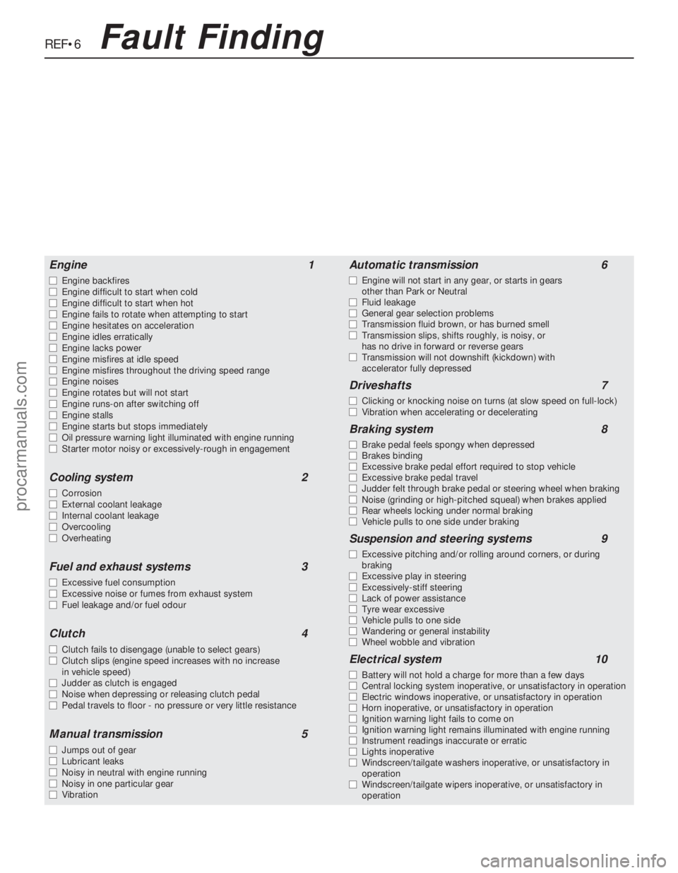
REF•6Fault Finding
Engine 1
m mEngine backfires
m mEngine difficult to start when cold
m mEngine difficult to start when hot
m mEngine fails to rotate when attempting to start
m mEngine hesitates on acceleration
m mEngine idles erratically
m mEngine lacks power
m mEngine misfires at idle speed
m mEngine misfires throughout the driving speed range
m mEngine noises
m mEngine rotates but will not start
m mEngine runs-on after switching off
m mEngine stalls
m mEngine starts but stops immediately
m mOil pressure warning light illuminated with engine running
m mStarter motor noisy or excessively-rough in engagement
Cooling system 2
m
mCorrosion
m mExternal coolant leakage
m mInternal coolant leakage
m mOvercooling
m mOverheating
Fuel and exhaust systems 3
m
mExcessive fuel consumption
m mExcessive noise or fumes from exhaust system
m mFuel leakage and/or fuel odour
Clutch 4
m
mClutch fails to disengage (unable to select gears)
m mClutch slips (engine speed increases with no increase
in vehicle speed)
m mJudder as clutch is engaged
m mNoise when depressing or releasing clutch pedal
m mPedal travels to floor - no pressure or very little resistance
Manual transmission 5
m
mJumps out of gear
m mLubricant leaks
m mNoisy in neutral with engine running
m mNoisy in one particular gear
m mVibration
Automatic transmission 6
m
mEngine will not start in any gear, or starts in gears
other than Park or Neutral
m mFluid leakage
m mGeneral gear selection problems
m mTransmission fluid brown, or has burned smell
m mTransmission slips, shifts roughly, is noisy, or
has no drive in forward or reverse gears
m mTransmission will not downshift (kickdown) with
accelerator fully depressed
Driveshafts 7
m mClicking or knocking noise on turns (at slow speed on full-lock)
m mVibration when accelerating or decelerating
Braking system 8
m
mBrake pedal feels spongy when depressed
m mBrakes binding
m mExcessive brake pedal effort required to stop vehicle
m mExcessive brake pedal travel
m mJudder felt through brake pedal or steering wheel when braking
m mNoise (grinding or high-pitched squeal) when brakes applied
m mRear wheels locking under normal braking
m mVehicle pulls to one side under braking
Suspension and steering systems 9
m
mExcessive pitching and/or rolling around corners, or during
braking
m mExcessive play in steering
m mExcessively-stiff steering
m mLack of power assistance
m mTyre wear excessive
m mVehicle pulls to one side
m mWandering or general instability
m mWheel wobble and vibration
Electrical system 10
m
mBattery will not hold a charge for more than a few days
m mCentral locking system inoperative, or unsatisfactory in operation
m mElectric windows inoperative, or unsatisfactory in operation
m mHorn inoperative, or unsatisfactory in operation
m mIgnition warning light fails to come on
m mIgnition warning light remains illuminated with engine running
m mInstrument readings inaccurate or erratic
m mLights inoperative
m mWindscreen/tailgate washers inoperative, or unsatisfactory in
operation
m mWindscreen/tailgate wipers inoperative, or unsatisfactory in
operation
procarmanuals.com
Page 268 of 279
REF•9
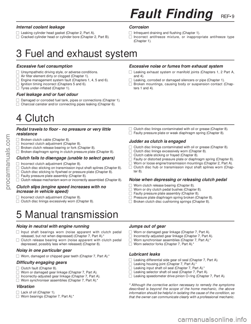
Excessive fuel consumption
m mUnsympathetic driving style, or adverse conditions.
m mAir filter element dirty or clogged (Chapter 1).
m mEngine management system fault (Chapters 1, 4, 5 and 6).
m mIgnition timing incorrect (Chapters 5 and 6).
m mTyres under-inflated (Chapter 1).
Fuel leakage and/or fuel odour
m
mDamaged or corroded fuel tank, pipes or connections (Chapter 1).
m mCharcoal canister and/or connecting pipes leaking (Chapter 6).
Excessive noise or fumes from exhaust system
m
mLeaking exhaust system or manifold joints (Chapters 1, 2 Part A,
and 4).
m mLeaking, corroded or damaged silencers or pipe (Chapter 1).
m mBroken mountings, causing body or suspension contact (Chap-
ters 1 and 4).
Fault Finding
3 Fuel and exhaust system
Noisy in neutral with engine running
m mInput shaft bearings worn (noise apparent with clutch pedal
released, but not when depressed) (Chapter 7, Part A).*
m mClutch release bearing worn (noise apparent with clutch pedal
depressed, possibly less when released) (Chapter 8).
Noisy in one particular gear
m mWorn, damaged or chipped gear teeth (Chapter 7, Part A).*
Difficulty engaging gears
m
mClutch fault (Chapter 8).
m mWorn or damaged gear linkage (Chapter 7, Part A).
m mIncorrectly-adjusted gear linkage (Chapter 7, Part A).
m mWorn synchroniser assemblies (Chapter 7, Part A).*
Vibration
m
mLack of oil (Chapter 1).
m mWorn bearings (Chapter 7, Part A).*
Jumps out of gear
m
mWorn or damaged gear linkage (Chapter 7, Part A).
m mIncorrectly-adjusted gear linkage (Chapter 7, Part A).
m mWorn synchroniser assemblies (Chapter 7, Part A).*
m mWorn selector forks (Chapter 7, Part A).*
Lubricant leaks
m
mLeaking differential side gear oil seal (Chapter 7, Part A).
m mLeaking housing joint (Chapter 7, Part A).*
m mLeaking input shaft oil seal (Chapter 7, Part A).*
m mLeaking selector shaft oil seal (Chapter 7, Part A).
m mLeaking speedometer drive pinion O-ring (Chapter 7, Part A).
* Although the corrective action necessary to remedy the symptoms
described is beyond the scope of the home mechanic, the above
information should be helpful in isolating the cause of the condition, so
that the owner can communicate clearly with a professional mechanic.
4 Clutch
5 Manual transmission
Pedal travels to floor - no pressure or very little
resistance
m mBroken clutch cable (Chapter 8).
m mIncorrect clutch adjustment (Chapter 8).
m mBroken clutch release bearing or fork (Chapter 8).
m mBroken diaphragm spring in clutch pressure plate (Chapter 8).
Clutch fails to disengage (unable to select gears)
m
mIncorrect clutch adjustment (Chapter 8).
m mClutch disc sticking on transmission input shaft splines (Chapter 8).
m mClutch disc sticking to flywheel or pressure plate (Chapter 8).
m mFaulty pressure plate assembly (Chapter 8).
m mClutch release mechanism worn or incorrectly assembled (Chapter 8).
Clutch slips (engine speed increases with no
increase in vehicle speed)
m mIncorrect clutch adjustment (Chapter 8).
m mClutch disc linings excessively worn (Chapter 8).m mClutch disc linings contaminated with oil or grease (Chapter 8).
m mFaulty pressure plate or weak diaphragm spring (Chapter 8).
Judder as clutch is engaged
m
mClutch disc linings contaminated with oil or grease (Chapter 8).
m mClutch disc linings excessively worn (Chapter 8).
m mClutch cable sticking or frayed (Chapter 8).
m mFaulty or distorted pressure plate or diaphragm spring (Chapter 8).
m mWorn or loose engine/transmission mountings (Chapter 2, Part A).
m mClutch disc hub or transmission input shaft splines worn (Chap-
ter 8).
Noise when depressing or releasing clutch pedal
m mWorn clutch release bearing (Chapter 8).
m mWorn or dry clutch pedal bushes (Chapter 8).
m mFaulty pressure plate assembly (Chapter 8).
m mPressure plate diaphragm spring broken (Chapter 8).
m mBroken clutch disc cushioning springs (Chapter 8).
Internal coolant leakage
m
mLeaking cylinder head gasket (Chapter 2, Part A).
m mCracked cylinder head or cylinder bore (Chapter 2, Part B).
Corrosion
m
mInfrequent draining and flushing (Chapter 1).
m mIncorrect antifreeze mixture, or inappropriate antifreeze type
(Chapter 1).
procarmanuals.com
Page 277 of 279
REF•18Index
E
Earth fault - 12•4
Economy/Sport mode switch - 12•7
ECU (Electronic Control Unit) - 6•10, 6•11,
6•12
EGR exhaust gas pressure differential
sensor - 6•16
EGR system - 6•15, 6•16
Electric shock - 0•5
Electric windows fault - REF•12
Electrical system - 0•8, 1•11, 1•20
Electrical system fault - REF•12
Electrically-operated windows - 12•7
Electrolyte - 1•8
Electronic control system - 4•9, 6•2
Emblems - 11•17
Emission checks - 0•10
Emissions control systems - 6•1
Engine compartment light - 12•11
Engine electrical systems- 5•1et seq
Engine fault finding - REF•7, REF•8, REF•10
Engine management system - 4•8, 4•9
Engine oil - 1•2, 1•6, 1•16
Engine oil level sensor - 12•18
Engine removal and general engine
overhaul procedures- 2B•1et seq
Environmental considerations - REF•4
Evaporative emissions control (EVAP)
system - 6•14
Evaporator - 3•9
Exhaust gas pressure differential sensor -
6•11, 6•12, 6•13
Exhaust Gas Recirculation (EGR) system -
6•15, 6•16
Exhaust manifold - 2A•8
Exhaust system - 0•9, 0•10, 1•18, 4•12,
REF•9
Expansion tank - 3•5, 3•6
FFacia - 11•21, 11•23
Fan(s) - 3•4, 12•11
Fault code read-out - 6•6
Fault finding- REF•6et seq
Fault finding - automatic transmission -
7B•1
Fault finding - electrical system - 12•4
Filling - 11•3
Fire - 0•5
Fluid level checks - 1•6
Flywheel - 2A•24
Foglight - 12•7, 12•9, 12•13
Foglight warning indicator - 12•11
Fuel and exhaust systems- 0•10, 4•1et
seq
Fuel and exhaust system fault finding -
REF•9
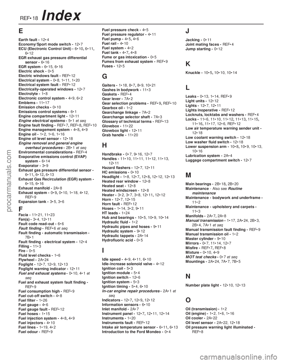
Fuel consumption high - REF•9
Fuel cut-off switch - 4•8
Fuel filter - 1•26
Fuel gauge - 4•6
Fuel gauge fault - REF•12
Fuel hoses - 1•15
Fuel injection system - 4•8, 4•9
Fuel injectors - 4•10
Fuel lines - 1•19, 4•2
Fuel odour - REF•9Fuel pressure check - 4•5
Fuel pressure regulator - 4•11
Fuel pump - 4•5, 4•6
Fuel rail - 4•10
Fuel system - 4•2
Fuel tank - 4•7, 4•8
Fume or gas intoxication - 0•5
Fumes from exhaust system - REF•9
Fuses - 12•5
G
Gaiters - 1•18, 8•7, 8•9, 10•21
Gashes in bodywork - 11•3
Gaskets - REF•4
Gear lever - 7A•2
Gear selection problems - REF•9, REF•10
Gearbox oil - 1•2
Gearchange linkage - 7A•2
Gearchange selector shaft - 7A•3
Glossary of technical terms - REF•13
Glovebox - 11•22
Glovebox light - 12•11
Grab handle - 11•20
H
Handbrake - 0•7, 9•16, 12•7
Handles - 11•10, 11•11, 11•12, 11•13,
12•11
Hazard flashers - 12•7, 12•11
HC emissions - 0•10
Headlight - 1•8, 12•7, 12•8, 12•12, 12•13
Heated rear window - 12•8
Heated seat - 12•8
Heated windscreen - 12•8
Heater - 3•2, 3•7, 3•8, 12•11, 12•12
Horn - 12•7, 12•15
Horn fault - REF•12
Hoses - 1•14, 3•2, 9•11
HT leads - 1•24
Hub and bearings - 10•5, 10•9, 10•14
Hydraulic fluid - 1•2
Hydraulic pipes and hoses - 9•11
Hydraulic system - 9•12
Hydraulic tappets - 2A•14
Hydrofluoric acid - 0•5
I
Idle speed - 4•9, 4•11, 6•10
Idle-increase solenoid valve - 4•12
Ignition coil - 5•3
Ignition module - 5•4
Ignition switch - 12•6
Ignition system - 5•3
Ignition timing - 5•4, 6•10
In-car engine repair procedures- 2A•1et
seq
Indicators - 12•7, 12•9, 12•12
Information sensors - 6•10
Inlet manifold - 2A•7
Instrument panel - 12•7, 12•11, 12•14
Instruments - 1•20
Instruments fault - REF•12
Intake air temperature sensor - 6•11, 6•13
Introduction to the Ford Mondeo - 0•4
J
Jacking - 0•11
Joint mating faces - REF•4
Jump starting - 0•12
K
Knuckle - 10•5, 10•10, 10•14
L
Leaks - 0•13, 1•14, REF•9
Light units - 12•12
Lights - 12•7, 12•11
Lights inoperative - REF•12
Locknuts, locktabs and washers - REF•4
Locks - 11•6, 11•10, 11•12, 11•13, 11•15,
11•16, 11•17, 12•6, REF•12
Low air temperature warning sender unit -
12•18
Low coolant warning switch - 12•18
Low washer fluid switch - 12•18
Lower suspension arm - 10•8, 10•9, 10•13,
10•16
Lubrication system - 2A•4
Luggage compartment switch - 12•7
M
Main bearings - 2B•18, 2B•20
Maintenance- Also see Routine
maintenance
Maintenance - bodywork and underframe -
11•2
Maintenance - upholstery and carpets -
11•3
Manifolds - 2A•7, 2A•8
Manual transmission- 1•17, 2A•24, 2B•3,
2B•4, 7A•1et seq
Manual transmission fault finding - REF•9
Manual transmission oil - 1•2
Master cylinder - 9•10
Mirrors - 0•7, 11•14, 12•7
Misfire - REF•7, REF•8
Mixture - 0•10, 4•9
MOT test checks- 0•7et seq
Mountings - 2A•24, 7A•7, 7B•5
N
Number plate light - 12•10, 12•13
O
Oil (transmission) - 1•2
Oil (engine) - 1•2, 1•6, 1•16
Oil cooler - 2A•22
Oil level sensor - 2A•22, 12•18
Oil pressure warning light illuminated -
REF•8
procarmanuals.com