1993 FORD MONDEO sensor
[x] Cancel search: sensorPage 18 of 279
1•4
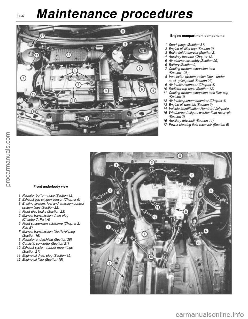
Engine compartment components
1 Spark plugs (Section 31)
2 Engine oil filler cap (Section 3)
3 Brake fluid reservoir (Section 3)
4 Auxiliary fusebox (Chapter 12)
5 Air cleaner assembly (Section 29)
6 Battery (Section 9)
7 Cooling system expansion tank
(Section 28)
8 Ventilation system pollen filter - under
cowl grille panel (Section 27)
9 Air intake resonator (Chapter 4)
10 Radiator top hose (Section 12)
11 Cooling system expansion tank filler cap
(Section 3)
12 Air intake plenum chamber (Chapter 4)
13 Engine oil dipstick (Section 3)
14 Vehicle Identification Number (VIN) plate
15 Windscreen/tailgate washer fluid reservoir
(Section 3)
16 Auxiliary drivebelt (Section 11)
17 Power steering fluid reservoir (Section 5)
Front underbody view
1 Radiator bottom hose (Section 12)
2 Exhaust gas oxygen sensor (Chapter 6)
3 Braking system, fuel and emission control
system lines (Section 22)
4 Front disc brake (Section 23)
5 Manual transmission drain plug
(Chapter 7, Part A)
6 Front suspension subframe (Chapter 2,
Part B)
7 Manual transmission filler/level plug
(Section 16)
8 Radiator undershield (Section 28)
9 Catalytic converter (Section 21)
10 Exhaust system rubber mountings
(Section 21)
11 Engine oil drain plug (Section 15)
12 Engine oil filter (Section 15)
Maintenance procedures
procarmanuals.com
Page 41 of 279
Chapter 2 Part A:
In-car engine repair procedures
Auxiliary drivebelt check and renewal . . . . . . . . . . . . . See Chapter 1
Camshaft oil seals - renewal . . . . . . . . . . . . . . . . . . . . . . . . . . . . . . . 12
Camshafts and hydraulic tappets - removal, inspection
and refitting . . . . . . . . . . . . . . . . . . . . . . . . . . . . . . . . . . . . . . . . . . 13
Compression test - description and interpretation . . . . . . . . . . . . . . 3
Crankshaft oil seals - renewal . . . . . . . . . . . . . . . . . . . . . . . . . . . . . . 20
Crankshaft pulley - removal and refitting . . . . . . . . . . . . . . . . . . . . . 8
Cylinder head - removal and refitting . . . . . . . . . . . . . . . . . . . . . . . . 14
Cylinder head and valve components - cleaning and
inspection . . . . . . . . . . . . . . . . . . . . . . . . . . . . . . . . . . . See Chapter 2B
Cylinder head cover - removal and refitting . . . . . . . . . . . . . . . . . . . 5
Engine oil and filter change . . . . . . . . . . . . . . . . . . . . . See Chapter 1
Engine oil level check . . . . . . . . . . . . . . . . . . . . . . . . . . See Chapter 1
Engine overhaul - general information . . . . . . . . . . . . . See Chapter 2B
Engine/transmission - removal and refitting . . . . . . . . See Chapter 2B
Engine/transmission mountings - inspection and renewal . . . . . . . . 22
Exhaust manifold - removal, inspection and refitting . . . . . . . . . . . . 7Flywheel/driveplate - removal, inspection and refitting . . . . . . . . . . 21
General information . . . . . . . . . . . . . . . . . . . . . . . . . . . . . . . . . . . . . . 1
Inlet manifold - removal and refitting . . . . . . . . . . . . . . . . . . . . . . . . 6
Oil cooler - removal and refitting . . . . . . . . . . . . . . . . . . . . . . . . . . . . 17
Oil level sensor - removal and refitting . . . . . . . . . . . . . . . . . . . . . . . 18
Oil pressure warning light switch - removal and refitting . . . . . . . . . 19
Oil pump - removal, inspection and refitting . . . . . . . . . . . . . . . . . . . 16
Repair operations possible with the engine in the vehicle . . . . . . . . 2
Spark plug renewal . . . . . . . . . . . . . . . . . . . . . . . . . . . See Chapter 1
Sump - removal and refitting . . . . . . . . . . . . . . . . . . . . . . . . . . . . . . . 15
Timing belt - removal, refitting and adjustment . . . . . . . . . . . . . . . . 10
Timing belt covers - removal and refitting . . . . . . . . . . . . . . . . . . . . . 9
Timing belt tensioner and toothed pulleys - removal,
inspection and refitting . . . . . . . . . . . . . . . . . . . . . . . . . . . . . . . . . 11
Top Dead Centre (TDC) for No 1 piston - locating . . . . . . . . . . . . . . 4
Water pump - removal and refitting . . . . . . . . . . . . . . . See Chapter 3
General
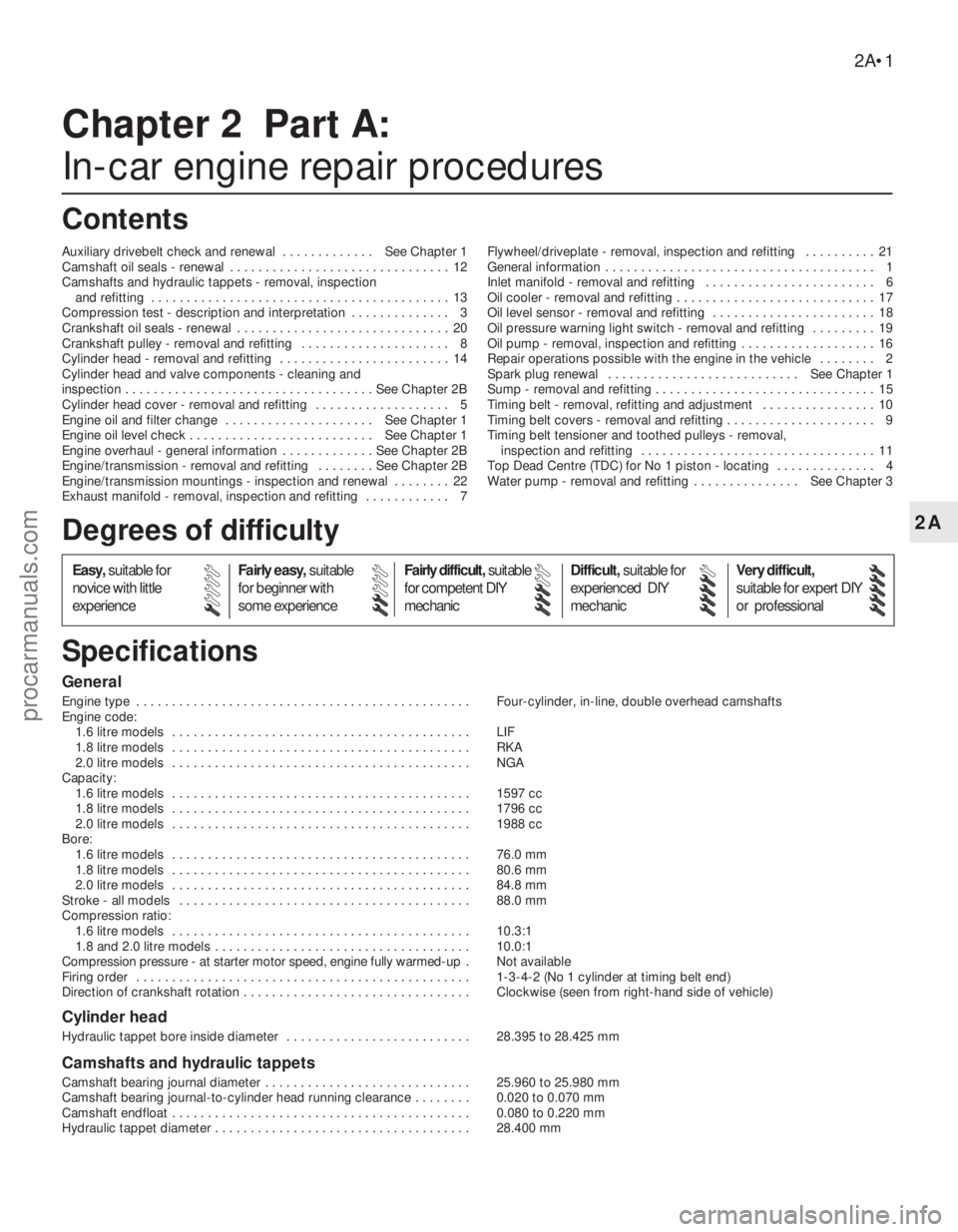
Engine type . . . . . . . . . . . . . . . . . . . . . . . . . . . . . . . . . . . . . . . . . . . . . . . Four-cylinder, in-line, double overhead camshafts
Engine code:
1.6 litre models . . . . . . . . . . . . . . . . . . . . . . . . . . . . . . . . . . . . . . . . . . LIF
1.8 litre models . . . . . . . . . . . . . . . . . . . . . . . . . . . . . . . . . . . . . . . . . . RKA
2.0 litre models . . . . . . . . . . . . . . . . . . . . . . . . . . . . . . . . . . . . . . . . . . NGA
Capacity:
1.6 litre models . . . . . . . . . . . . . . . . . . . . . . . . . . . . . . . . . . . . . . . . . . 1597 cc
1.8 litre models . . . . . . . . . . . . . . . . . . . . . . . . . . . . . . . . . . . . . . . . . . 1796 cc
2.0 litre models . . . . . . . . . . . . . . . . . . . . . . . . . . . . . . . . . . . . . . . . . . 1988 cc
Bore:
1.6 litre models . . . . . . . . . . . . . . . . . . . . . . . . . . . . . . . . . . . . . . . . . . 76.0 mm
1.8 litre models . . . . . . . . . . . . . . . . . . . . . . . . . . . . . . . . . . . . . . . . . . 80.6 mm
2.0 litre models . . . . . . . . . . . . . . . . . . . . . . . . . . . . . . . . . . . . . . . . . . 84.8 mm
Stroke - all models . . . . . . . . . . . . . . . . . . . . . . . . . . . . . . . . . . . . . . . . . 88.0 mm
Compression ratio:
1.6 litre models . . . . . . . . . . . . . . . . . . . . . . . . . . . . . . . . . . . . . . . . . . 10.3:1
1.8 and 2.0 litre models . . . . . . . . . . . . . . . . . . . . . . . . . . . . . . . . . . . . 10.0:1
Compression pressure - at starter motor speed, engine fully warmed-up .Not available
Firing order . . . . . . . . . . . . . . . . . . . . . . . . . . . . . . . . . . . . . . . . . . . . . . . 1-3-4-2 (No 1 cylinder at timing belt end)
Direction of crankshaft rotation . . . . . . . . . . . . . . . . . . . . . . . . . . . . . . . . Clockwise (seen from right-hand side of vehicle)
Cylinder head
Hydraulic tappet bore inside diameter . . . . . . . . . . . . . . . . . . . . . . . . . . 28.395 to 28.425 mm
Camshafts and hydraulic tappets
Camshaft bearing journal diameter . . . . . . . . . . . . . . . . . . . . . . . . . . . . . 25.960 to 25.980 mm
Camshaft bearing journal-to-cylinder head running clearance . . . . . . . . 0.020 to 0.070 mm
Camshaft endfloat . . . . . . . . . . . . . . . . . . . . . . . . . . . . . . . . . . . . . . . . . . 0.080 to 0.220 mm
Hydraulic tappet diameter . . . . . . . . . . . . . . . . . . . . . . . . . . . . . . . . . . . . 28.400 mm
2A•1
Easy,suitable for
novice with little
experienceFairly easy,suitable
for beginner with
some experienceFairly difficult,suitable
for competent DIY
mechanicDifficult,suitable for
experienced DIY
mechanicVery difficult,
suitable for expert DIY
or professional
Degrees of difficulty
Specifications Contents2A
procarmanuals.com
Page 42 of 279
Lubrication
Engine oil type/specification . . . . . . . . . . . . . . . . . . . . . . . . . . . . . . . . . . See Chapter 1
Engine oil capacity . . . . . . . . . . . . . . . . . . . . . . . . . . . . . . . . . . . . . . . . . See Chapter 1
Oil pressure . . . . . . . . . . . . . . . . . . . . . . . . . . . . . . . . . . . . . . . . . . . . . . . No information available at time of writing
Oil pump clearances . . . . . . . . . . . . . . . . . . . . . . . . . . . . . . . . . . . . . . . . No information available at time of writing
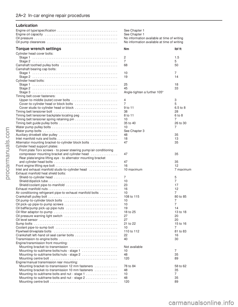
Torque wrench settingsNm lbf ft
Cylinder head cover bolts:
Stage 1 . . . . . . . . . . . . . . . . . . . . . . . . . . . . . . . . . . . . . . . . . . . . . . . . 2 1.5
Stage 2 . . . . . . . . . . . . . . . . . . . . . . . . . . . . . . . . . . . . . . . . . . . . . . . . 7 5
Camshaft toothed pulley bolts . . . . . . . . . . . . . . . . . . . . . . . . . . . . . . . . 68 50
Camshaft bearing cap bolts:
Stage 1 . . . . . . . . . . . . . . . . . . . . . . . . . . . . . . . . . . . . . . . . . . . . . . . . 10 7
Stage 2 . . . . . . . . . . . . . . . . . . . . . . . . . . . . . . . . . . . . . . . . . . . . . . . . 19 14
Cylinder head bolts:
Stage 1 . . . . . . . . . . . . . . . . . . . . . . . . . . . . . . . . . . . . . . . . . . . . . . . . 25 18
Stage 2 . . . . . . . . . . . . . . . . . . . . . . . . . . . . . . . . . . . . . . . . . . . . . . . . 45 33
Stage 3 . . . . . . . . . . . . . . . . . . . . . . . . . . . . . . . . . . . . . . . . . . . . . . . . Angle-tighten a further 105°
Timing belt cover fasteners:
Upper-to-middle (outer) cover bolts . . . . . . . . . . . . . . . . . . . . . . . . . . 4 3
Cover-to-cylinder head or block bolts . . . . . . . . . . . . . . . . . . . . . . . . 7 5
Cover studs-to-cylinder head or block . . . . . . . . . . . . . . . . . . . . . . . . 9 to 11 6.5 to 8
Timing belt tensioner bolt . . . . . . . . . . . . . . . . . . . . . . . . . . . . . . . . . . . . 38 28
Timing belt tensioner backplate locating peg . . . . . . . . . . . . . . . . . . . . . 8 to 11 6 to 8
Timing belt tensioner spring retaining pin . . . . . . . . . . . . . . . . . . . . . . . . 10 7
Timing belt guide pulley bolts . . . . . . . . . . . . . . . . . . . . . . . . . . . . . . . . . 35 to 40 26 to 30
Water pump pulley bolts . . . . . . . . . . . . . . . . . . . . . . . . . . . . . . . . . . . . . 10 7
Water pump bolts . . . . . . . . . . . . . . . . . . . . . . . . . . . . . . . . . . . . . . . . . . See Chapter 3
Auxiliary drivebelt idler pulley . . . . . . . . . . . . . . . . . . . . . . . . . . . . . . . . . 48 35
Inlet manifold nuts and bolts . . . . . . . . . . . . . . . . . . . . . . . . . . . . . . . . . . 18 13
Alternator mounting bracket-to-cylinder block bolts . . . . . . . . . . . . . . . 47 35
Cylinder head support plates:
Front plate Torx screws - to power steering pump/air conditioning
compressor mounting bracket and cylinder head . . . . . . . . . . . . . . . 47 35
Rear plate/engine lifting eye - to alternator mounting bracket
and cylinder head bolts . . . . . . . . . . . . . . . . . . . . . . . . . . . . . . . . . . . . 47 35
Front engine lifting eye bolt . . . . . . . . . . . . . . . . . . . . . . . . . . . . . . . . . . . 16 12
Inlet and exhaust manifold studs-to-cylinder head . . . . . . . . . . . . . . . . 10 maximum 7 maximum
Exhaust manifold heat shield bolts:
Shield-to-cylinder head . . . . . . . . . . . . . . . . . . . . . . . . . . . . . . . . . . . . 7 5
Shield/dipstick tube . . . . . . . . . . . . . . . . . . . . . . . . . . . . . . . . . . . . . . . 10 7
Shield/coolant pipe-to-manifold . . . . . . . . . . . . . . . . . . . . . . . . . . . . . 23 17
Exhaust manifold nuts . . . . . . . . . . . . . . . . . . . . . . . . . . . . . . . . . . . . . . . 16 12
Air conditioning refrigerant pipe-to-exhaust manifold bolts . . . . . . . . . . 10 7
Crankshaft pulley bolt . . . . . . . . . . . . . . . . . . . . . . . . . . . . . . . . . . . . . . . 108 to 115 80 to 85
Oil pump-to-cylinder block bolts . . . . . . . . . . . . . . . . . . . . . . . . . . . . . . 10 7
Oil pick-up pipe-to-pump screws . . . . . . . . . . . . . . . . . . . . . . . . . . . . . . 10 7
Oil baffle/pump pick-up pipe nuts . . . . . . . . . . . . . . . . . . . . . . . . . . . . . 19 14
Oil filter adaptor-to-pump . . . . . . . . . . . . . . . . . . . . . . . . . . . . . . . . . . . . 18 to 25 13 to 18
Oil pressure warning light switch . . . . . . . . . . . . . . . . . . . . . . . . . . . . . . 27 20
Oil level sensor . . . . . . . . . . . . . . . . . . . . . . . . . . . . . . . . . . . . . . . . . . . . 27 20
Sump bolts . . . . . . . . . . . . . . . . . . . . . . . . . . . . . . . . . . . . . . . . . . . . . . . 21 to 22 15 to 16
Coolant pipe-to-sump bolt . . . . . . . . . . . . . . . . . . . . . . . . . . . . . . . . . . . 10 7
Flywheel/driveplate bolts . . . . . . . . . . . . . . . . . . . . . . . . . . . . . . . . . . . . 110 to 112 81 to 83
Crankshaft left-hand oil seal carrier bolts . . . . . . . . . . . . . . . . . . . . . . . . 22 16
Transmission-to-engine bolts . . . . . . . . . . . . . . . . . . . . . . . . . . . . . . . . . 40 30
Engine/transmission front mounting:
Mounting bracket-to-transmission . . . . . . . . . . . . . . . . . . . . . . . . . . . Not available
Mounting-to-subframe bolts/nuts - stage 1 . . . . . . . . . . . . . . . . . . . . 10 7
Mounting-to-subframe bolts/nuts - stage 2 . . . . . . . . . . . . . . . . . . . . 48 35
Mounting centre bolt . . . . . . . . . . . . . . . . . . . . . . . . . . . . . . . . . . . . . . 120 89
Engine/manual transmission rear mounting:
Mounting bracket-to-transmission 12 mm fasteners . . . . . . . . . . . . . 78 to 84 58 to 62
Mounting bracket-to-transmission 10 mm fasteners . . . . . . . . . . . . . 48 35
Mounting-to-subframe bolts and nut - stage 1 . . . . . . . . . . . . . . . . . . 10 7
Mounting-to-subframe bolts and nut - stage 2 . . . . . . . . . . . . . . . . . . 48 35
Mounting centre bolt . . . . . . . . . . . . . . . . . . . . . . . . . . . . . . . . . . . . . . 120 89
2A•2 In-car engine repair procedures
procarmanuals.com
Page 47 of 279
throttle linkage as described in Chapter 4.
Where fitted, disconnect also the cruise
control actuator cable (see Chapter 12).
3Remove the timing belt upper cover (see
Section 9).
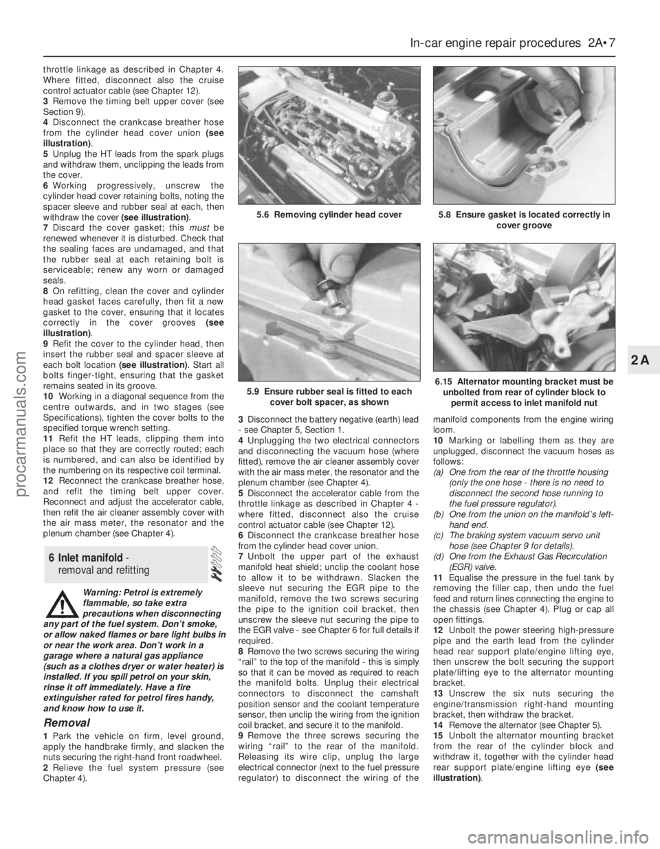
4Disconnect the crankcase breather hose
from the cylinder head cover union (see
illustration).
5Unplug the HT leads from the spark plugs
and withdraw them, unclipping the leads from
the cover.
6Working progressively, unscrew the
cylinder head cover retaining bolts, noting the
spacer sleeve and rubber seal at each, then
withdraw the cover (see illustration).
7Discard the cover gasket; this mustbe
renewed whenever it is disturbed. Check that
the sealing faces are undamaged, and that
the rubber seal at each retaining bolt is
serviceable; renew any worn or damaged
seals.
8On refitting, clean the cover and cylinder
head gasket faces carefully, then fit a new
gasket to the cover, ensuring that it locates
correctly in the cover grooves (see
illustration).
9Refit the cover to the cylinder head, then
insert the rubber seal and spacer sleeve at
each bolt location (see illustration). Start all
bolts finger-tight, ensuring that the gasket
remains seated in its groove.
10Working in a diagonal sequence from the
centre outwards, and in two stages (see
Specifications), tighten the cover bolts to the
specified torque wrench setting.
11Refit the HT leads, clipping them into
place so that they are correctly routed; each
is numbered, and can also be identified by
the numbering on its respective coil terminal.
12Reconnect the crankcase breather hose,
and refit the timing belt upper cover.
Reconnect and adjust the accelerator cable,
then refit the air cleaner assembly cover with
the air mass meter, the resonator and the
plenum chamber (see Chapter 4).
Warning: Petrol is extremely
flammable, so take extra
precautions when disconnecting
any part of the fuel system. Don’t smoke,
or allow naked flames or bare light bulbs in
or near the work area. Don’t work in a
garage where a natural gas appliance
(such as a clothes dryer or water heater) is
installed. If you spill petrol on your skin,
rinse it off immediately. Have a fire
extinguisher rated for petrol fires handy,
and know how to use it.
Removal
1Park the vehicle on firm, level ground,
apply the handbrake firmly, and slacken the
nuts securing the right-hand front roadwheel.
2Relieve the fuel system pressure (see
Chapter 4).3Disconnect the battery negative (earth) lead
- see Chapter 5, Section 1.
4Unplugging the two electrical connectors
and disconnecting the vacuum hose (where
fitted), remove the air cleaner assembly cover
with the air mass meter, the resonator and the
plenum chamber (see Chapter 4).
5Disconnect the accelerator cable from the
throttle linkage as described in Chapter 4 -
where fitted, disconnect also the cruise
control actuator cable (see Chapter 12).
6Disconnect the crankcase breather hose
from the cylinder head cover union.
7Unbolt the upper part of the exhaust
manifold heat shield; unclip the coolant hose
to allow it to be withdrawn. Slacken the
sleeve nut securing the EGR pipe to the
manifold, remove the two screws securing
the pipe to the ignition coil bracket, then
unscrew the sleeve nut securing the pipe to
the EGR valve - see Chapter 6 for full details if
required.
8Remove the two screws securing the wiring
“rail” to the top of the manifold - this is simply
so that it can be moved as required to reach
the manifold bolts. Unplug their electrical
connectors to disconnect the camshaft
position sensor and the coolant temperature
sensor, then unclip the wiring from the ignition
coil bracket, and secure it to the manifold.
9Remove the three screws securing the
wiring “rail” to the rear of the manifold.
Releasing its wire clip, unplug the large
electrical connector (next to the fuel pressure
regulator) to disconnect the wiring of themanifold components from the engine wiring
loom.
10Marking or labelling them as they are
unplugged, disconnect the vacuum hoses as
follows:
(a) One from the rear of the throttle housing
(only the one hose - there is no need to
disconnect the second hose running to
the fuel pressure regulator).
(b) One from the union on the manifold’s left-
hand end.
(c) The braking system vacuum servo unit
hose (see Chapter 9 for details).
(d) One from the Exhaust Gas Recirculation
(EGR) valve.
11Equalise the pressure in the fuel tank by
removing the filler cap, then undo the fuel
feed and return lines connecting the engine to
the chassis (see Chapter 4). Plug or cap all
open fittings.
12Unbolt the power steering high-pressure
pipe and the earth lead from the cylinder
head rear support plate/engine lifting eye,
then unscrew the bolt securing the support
plate/lifting eye to the alternator mounting
bracket.
13Unscrew the six nuts securing the
engine/transmission right-hand mounting
bracket, then withdraw the bracket.
14Remove the alternator (see Chapter 5).
15Unbolt the alternator mounting bracket
from the rear of the cylinder block and
withdraw it, together with the cylinder head
rear support plate/engine lifting eye (see
illustration).
6 Inlet manifold -
removal and refitting
In-car engine repair procedures 2A•7
2A
5.8 Ensure gasket is located correctly in
cover groove5.6 Removing cylinder head cover
5.9 Ensure rubber seal is fitted to each
cover bolt spacer, as shown6.15 Alternator mounting bracket must be
unbolted from rear of cylinder block to
permit access to inlet manifold nut
procarmanuals.com
Page 48 of 279
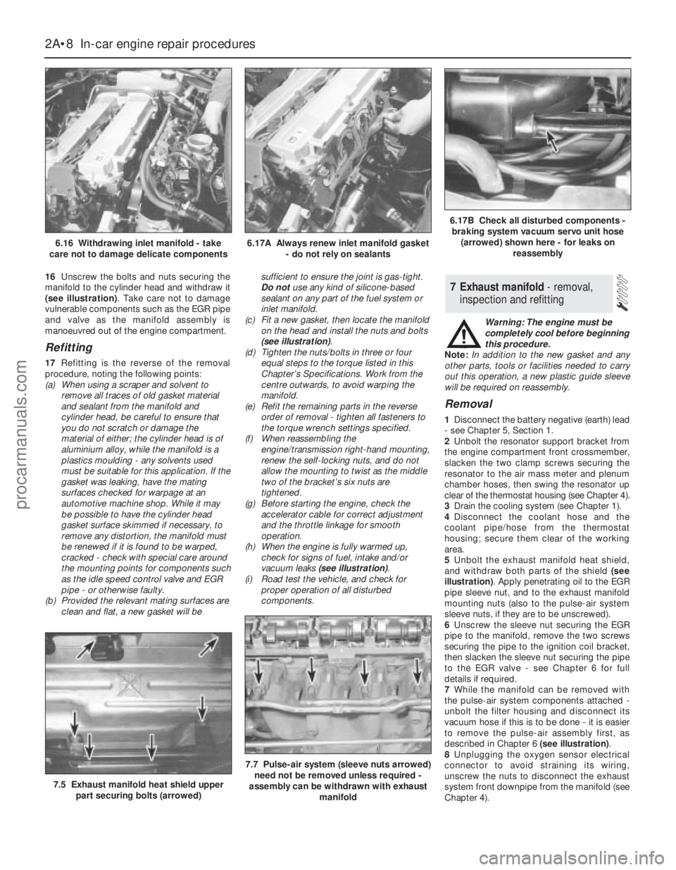
16Unscrew the bolts and nuts securing the
manifold to the cylinder head and withdraw it
(see illustration). Take care not to damage
vulnerable components such as the EGR pipe
and valve as the manifold assembly is
manoeuvred out of the engine compartment.
Refitting
17Refitting is the reverse of the removal
procedure, noting the following points:
(a) When using a scraper and solvent to
remove all traces of old gasket material
and sealant from the manifold and
cylinder head, be careful to ensure that
you do not scratch or damage the
material of either; the cylinder head is of
aluminium alloy, while the manifold is a
plastics moulding - any solvents used
must be suitable for this application. If the
gasket was leaking, have the mating
surfaces checked for warpage at an
automotive machine shop. While it may
be possible to have the cylinder head
gasket surface skimmed if necessary, to
remove any distortion, the manifold must
be renewed if it is found to be warped,
cracked - check with special care around
the mounting points for components such
as the idle speed control valve and EGR
pipe - or otherwise faulty.
(b) Provided the relevant mating surfaces are
clean and flat, a new gasket will besufficient to ensure the joint is gas-tight.
Do notuse any kind of silicone-based
sealant on any part of the fuel system or
inlet manifold.
(c) Fit a new gasket, then locate the manifold
on the head and install the nuts and bolts
(see illustration).
(d) Tighten the nuts/bolts in three or four
equal steps to the torque listed in this
Chapter’s Specifications. Work from the
centre outwards, to avoid warping the
manifold.
(e) Refit the remaining parts in the reverse
order of removal - tighten all fasteners to
the torque wrench settings specified.
(f) When reassembling the
engine/transmission right-hand mounting,
renew the self-locking nuts, and do not
allow the mounting to twist as the middle
two of the bracket’s six nuts are
tightened.
(g) Before starting the engine, check the
accelerator cable for correct adjustment
and the throttle linkage for smooth
operation.
(h) When the engine is fully warmed up,
check for signs of fuel, intake and/or
vacuum leaks (see illustration).
(i) Road test the vehicle, and check for
proper operation of all disturbed
components.Warning: The engine must be
completely cool before beginning
this procedure.
Note:In addition to the new gasket and any
other parts, tools or facilities needed to carry
out this operation, a new plastic guide sleeve
will be required on reassembly.
Removal
1Disconnect the battery negative (earth) lead
- see Chapter 5, Section 1.
2Unbolt the resonator support bracket from
the engine compartment front crossmember,
slacken the two clamp screws securing the
resonator to the air mass meter and plenum
chamber hoses, then swing the resonator up
clear of the thermostat housing (see Chapter 4).
3Drain the cooling system (see Chapter 1).
4Disconnect the coolant hose and the
coolant pipe/hose from the thermostat
housing; secure them clear of the working
area.
5Unbolt the exhaust manifold heat shield,
and withdraw both parts of the shield (see
illustration). Apply penetrating oil to the EGR
pipe sleeve nut, and to the exhaust manifold
mounting nuts (also to the pulse-air system
sleeve nuts, if they are to be unscrewed).
6Unscrew the sleeve nut securing the EGR
pipe to the manifold, remove the two screws
securing the pipe to the ignition coil bracket,
then slacken the sleeve nut securing the pipe
to the EGR valve - see Chapter 6 for full
details if required.
7While the manifold can be removed with
the pulse-air system components attached -
unbolt the filter housing and disconnect its
vacuum hose if this is to be done - it is easier
to remove the pulse-air assembly first, as
described in Chapter 6 (see illustration).
8Unplugging the oxygen sensor electrical
connector to avoid straining its wiring,
unscrew the nuts to disconnect the exhaust
system front downpipe from the manifold (see
Chapter 4).
7 Exhaust manifold - removal,
inspection and refitting
2A•8 In-car engine repair procedures
6.16 Withdrawing inlet manifold - take
care not to damage delicate components6.17A Always renew inlet manifold gasket
- do not rely on sealants
6.17B Check all disturbed components -
braking system vacuum servo unit hose
(arrowed) shown here - for leaks on
reassembly
7.5 Exhaust manifold heat shield upper
part securing bolts (arrowed)
7.7 Pulse-air system (sleeve nuts arrowed)
need not be removed unless required -
assembly can be withdrawn with exhaust
manifold
procarmanuals.com
Page 54 of 279
related components, to remove all traces of
oil. Fit a new belt on reassembly.
2If the timing belt is still clean, slip it off the
toothed pulley, taking care not to twist it too
sharply; use the fingers only to handle the
belt. Do notrotate the crankshaft until the
timing belt is refitted. Cover the belt, and
secure it so that it is clear of the working area
and cannot slip off the remaining toothed
pulley.
3Unfasten the pulley bolt and withdraw the
pulley (see Section 11).
4Unbolt the camshaft right-hand bearing
cap, and withdraw the defective oil seal.
Clean the seal housing, and polish off any
burrs or raised edges, which may have
caused the seal to fail in the first place.
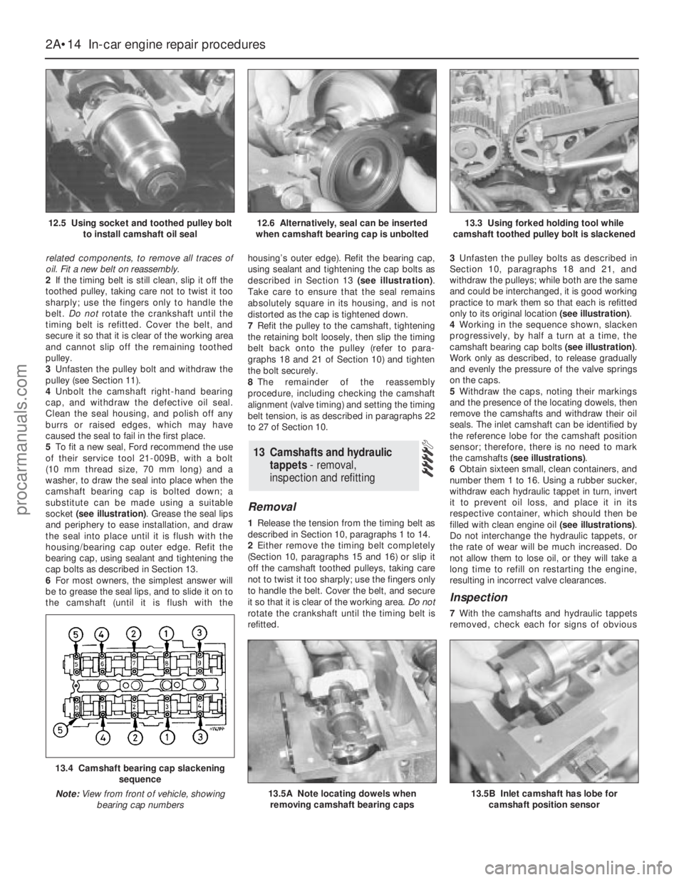
5To fit a new seal, Ford recommend the use
of their service tool 21-009B, with a bolt
(10 mm thread size, 70 mm long) and a
washer, to draw the seal into place when the
camshaft bearing cap is bolted down; a
substitute can be made using a suitable
socket (see illustration). Grease the seal lips
and periphery to ease installation, and draw
the seal into place until it is flush with the
housing/bearing cap outer edge. Refit the
bearing cap, using sealant and tightening the
cap bolts as described in Section 13.
6For most owners, the simplest answer will
be to grease the seal lips, and to slide it on to
the camshaft (until it is flush with thehousing’s outer edge). Refit the bearing cap,
using sealant and tightening the cap bolts as
described in Section 13 (see illustration).
Take care to ensure that the seal remains
absolutely square in its housing, and is not
distorted as the cap is tightened down.
7Refit the pulley to the camshaft, tightening
the retaining bolt loosely, then slip the timing
belt back onto the pulley (refer to para-
graphs 18 and 21 of Section 10) and tighten
the bolt securely.
8The remainder of the reassembly
procedure, including checking the camshaft
alignment (valve timing) and setting the timing
belt tension, is as described in paragraphs 22
to 27 of Section 10.
Removal
1Release the tension from the timing belt as
described in Section 10, paragraphs 1 to 14.
2Either remove the timing belt completely
(Section 10, paragraphs 15 and 16) or slip it
off the camshaft toothed pulleys, taking care
not to twist it too sharply; use the fingers only
to handle the belt. Cover the belt, and secure
it so that it is clear of the working area. Do not
rotate the crankshaft until the timing belt is
refitted.3Unfasten the pulley bolts as described in
Section 10, paragraphs 18 and 21, and
withdraw the pulleys; while both are the same
and could be interchanged, it is good working
practice to mark them so that each is refitted
only to its original location (see illustration).
4Working in the sequence shown, slacken
progressively, by half a turn at a time, the
camshaft bearing cap bolts (see illustration).
Work only as described, to release gradually
and evenly the pressure of the valve springs
on the caps.
5Withdraw the caps, noting their markings
and the presence of the locating dowels, then
remove the camshafts and withdraw their oil
seals. The inlet camshaft can be identified by
the reference lobe for the camshaft position
sensor; therefore, there is no need to mark
the camshafts (see illustrations).
6Obtain sixteen small, clean containers, and
number them 1 to 16. Using a rubber sucker,
withdraw each hydraulic tappet in turn, invert
it to prevent oil loss, and place it in its
respective container, which should then be
filled with clean engine oil (see illustrations).
Do not interchange the hydraulic tappets, or
the rate of wear will be much increased. Do
not allow them to lose oil, or they will take a
long time to refill on restarting the engine,
resulting in incorrect valve clearances.
Inspection
7With the camshafts and hydraulic tappets
removed, check each for signs of obvious
13 Camshafts and hydraulic
tappets - removal,
inspection and refitting
2A•14 In-car engine repair procedures
12.5 Using socket and toothed pulley bolt
to install camshaft oil seal12.6 Alternatively, seal can be inserted
when camshaft bearing cap is unbolted13.3 Using forked holding tool while
camshaft toothed pulley bolt is slackened
13.4 Camshaft bearing cap slackening
sequence
Note:View from front of vehicle, showing
bearing cap numbers
13.5A Note locating dowels when
removing camshaft bearing caps13.5B Inlet camshaft has lobe for
camshaft position sensor
procarmanuals.com
Page 56 of 279
away from the gauge, and note the gauge
reading. If the endfloat measured is found to
be at or beyond the specified service limit, fit
a new camshaft and repeat the check; if the
clearance is still excessive, the cylinder head
must be renewed.
Refitting
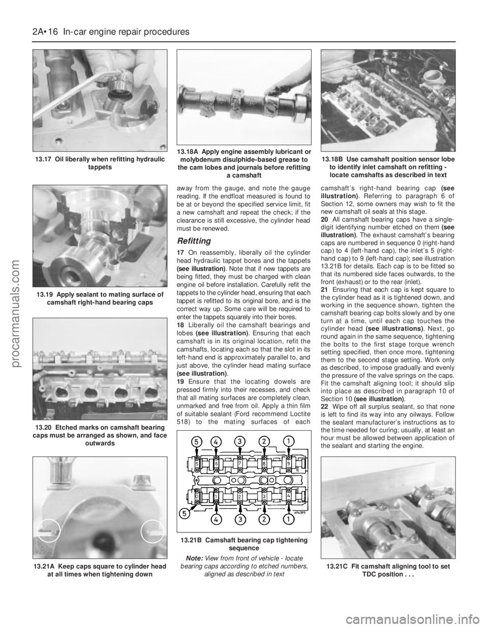
17On reassembly, liberally oil the cylinder
head hydraulic tappet bores and the tappets
(see illustration). Note that if new tappets are
being fitted, they must be charged with clean
engine oil before installation. Carefully refit the
tappets to the cylinder head, ensuring that each
tappet is refitted to its original bore, and is the
correct way up. Some care will be required to
enter the tappets squarely into their bores.
18Liberally oil the camshaft bearings and
lobes (see illustration). Ensuring that each
camshaft is in its original location, refit the
camshafts, locating each so that the slot in its
left-hand end is approximately parallel to, and
just above, the cylinder head mating surface
(see illustration).
19Ensure that the locating dowels are
pressed firmly into their recesses, and check
that all mating surfaces are completely clean,
unmarked and free from oil. Apply a thin film
of suitable sealant (Ford recommend Loctite
518) to the mating surfaces of eachcamshaft’s right-hand bearing cap (see
illustration). Referring to paragraph 6 of
Section 12, some owners may wish to fit the
new camshaft oil seals at this stage.
20All camshaft bearing caps have a single-
digit identifying number etched on them (see
illustration). The exhaust camshaft’s bearing
caps are numbered in sequence 0 (right-hand
cap) to 4 (left-hand cap), the inlet’s 5 (right-
hand cap) to 9 (left-hand cap); see illustration
13.21B for details. Each cap is to be fitted so
that its numbered side faces outwards, to the
front (exhaust) or to the rear (inlet).
21Ensuring that each cap is kept square to
the cylinder head as it is tightened down, and
working in the sequence shown, tighten the
camshaft bearing cap bolts slowly and by one
turn at a time, until each cap touches the
cylinder head (see illustrations). Next, go
round again in the same sequence, tightening
the bolts to the first stage torque wrench
setting specified, then once more, tightening
them to the second stage setting. Work only
as described, to impose gradually and evenly
the pressure of the valve springs on the caps.
Fit the camshaft aligning tool; it should slip
into place as described in paragraph 10 of
Section 10 (see illustration).
22Wipe off all surplus sealant, so that none
is left to find its way into any oilways. Follow
the sealant manufacturer’s instructions as to
the time needed for curing; usually, at least an
hour must be allowed between application of
the sealant and starting the engine.
2A•16 In-car engine repair procedures
13.17 Oil liberally when refitting hydraulic
tappets13.18A Apply engine assembly lubricant or
molybdenum disulphide-based grease to
the cam lobes and journals before refitting
a camshaft
13.19 Apply sealant to mating surface of
camshaft right-hand bearing caps
13.20 Etched marks on camshaft bearing
caps must be arranged as shown, and face
outwards
13.18B Use camshaft position sensor lobe
to identify inlet camshaft on refitting -
locate camshafts as described in text
13.21A Keep caps square to cylinder head
at all times when tightening down
13.21B Camshaft bearing cap tightening
sequence
Note:View from front of vehicle - locate
bearing caps according to etched numbers,
aligned as described in text
13.21C Fit camshaft aligning tool to set
TDC position . . .
procarmanuals.com
Page 58 of 279
14Unscrew the two nuts to disconnect the
exhaust system front downpipe from the
manifold (Chapter 4); disconnect the oxygen
sensor wiring, so that it is not strained by the
weight of the exhaust system.
15Remove the auxiliary drivebelt (see
Chapter 1).
16Support the weight of the
engine/transmission using a trolley jack, with
a wooden spacer to prevent damage to the
sump.
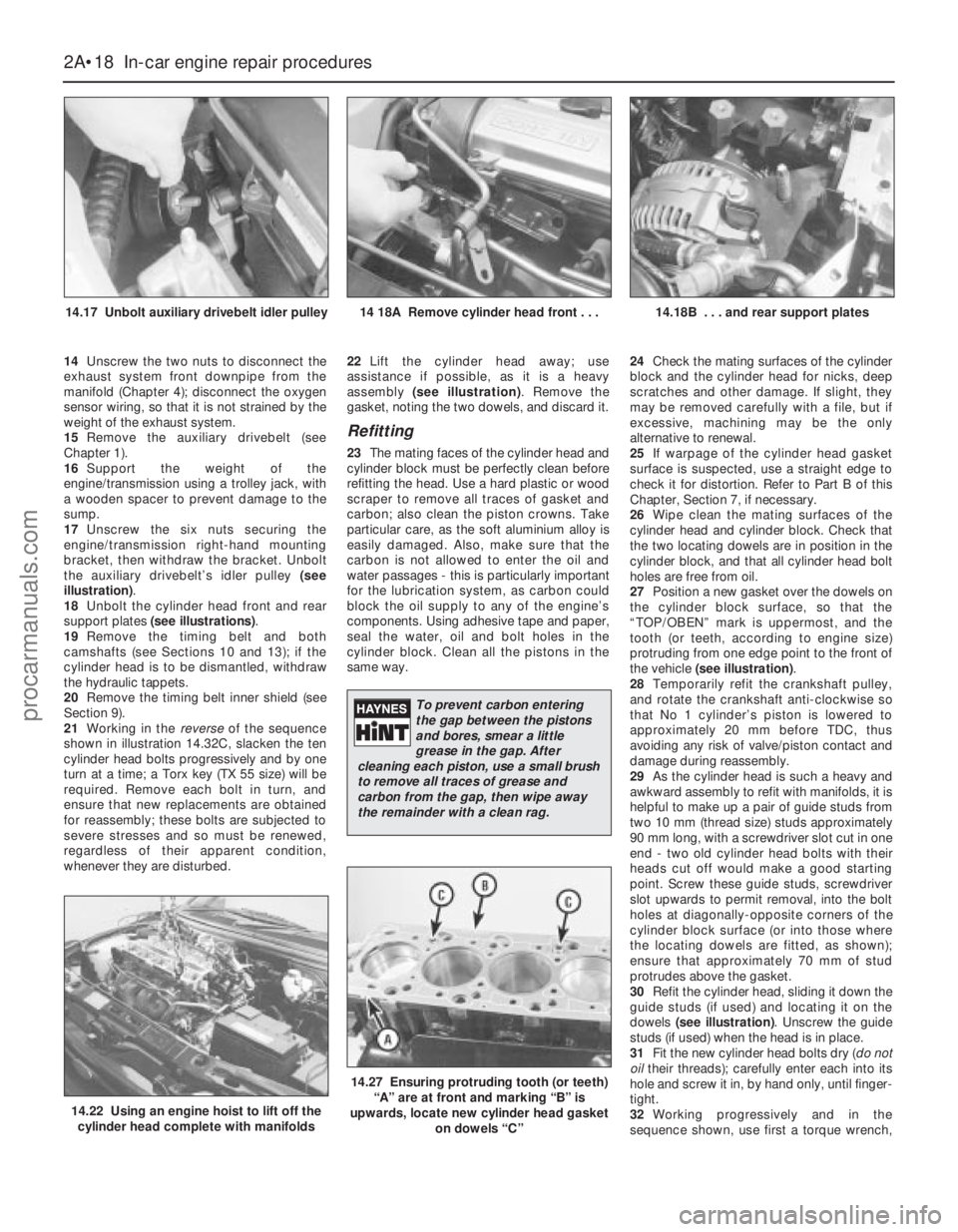
17Unscrew the six nuts securing the
engine/transmission right-hand mounting
bracket, then withdraw the bracket. Unbolt
the auxiliary drivebelt’s idler pulley (see
illustration).
18Unbolt the cylinder head front and rear
support plates (see illustrations).
19Remove the timing belt and both
camshafts (see Sections 10 and 13); if the
cylinder head is to be dismantled, withdraw
the hydraulic tappets.
20Remove the timing belt inner shield (see
Section 9).
21Working in the reverseof the sequence
shown in illustration 14.32C, slacken the ten
cylinder head bolts progressively and by one
turn at a time; a Torx key (TX 55 size) will be
required. Remove each bolt in turn, and
ensure that new replacements are obtained
for reassembly; these bolts are subjected to
severe stresses and so must be renewed,
regardless of their apparent condition,
whenever they are disturbed.22Lift the cylinder head away; use
assistance if possible, as it is a heavy
assembly (see illustration). Remove the
gasket, noting the two dowels, and discard it.
Refitting
23The mating faces of the cylinder head and
cylinder block must be perfectly clean before
refitting the head. Use a hard plastic or wood
scraper to remove all traces of gasket and
carbon; also clean the piston crowns. Take
particular care, as the soft aluminium alloy is
easily damaged. Also, make sure that the
carbon is not allowed to enter the oil and
water passages - this is particularly important
for the lubrication system, as carbon could
block the oil supply to any of the engine’s
components. Using adhesive tape and paper,
seal the water, oil and bolt holes in the
cylinder block. Clean all the pistons in the
same way.24Check the mating surfaces of the cylinder
block and the cylinder head for nicks, deep
scratches and other damage. If slight, they
may be removed carefully with a file, but if
excessive, machining may be the only
alternative to renewal.
25If warpage of the cylinder head gasket
surface is suspected, use a straight edge to
check it for distortion. Refer to Part B of this
Chapter, Section 7, if necessary.
26Wipe clean the mating surfaces of the
cylinder head and cylinder block. Check that
the two locating dowels are in position in the
cylinder block, and that all cylinder head bolt
holes are free from oil.
27Position a new gasket over the dowels on
the cylinder block surface, so that the
“TOP/OBEN” mark is uppermost, and the
tooth (or teeth, according to engine size)
protruding from one edge point to the front of
the vehicle (see illustration).
28Temporarily refit the crankshaft pulley,
and rotate the crankshaft anti-clockwise so
that No 1 cylinder’s piston is lowered to
approximately 20 mm before TDC, thus
avoiding any risk of valve/piston contact and
damage during reassembly.
29As the cylinder head is such a heavy and
awkward assembly to refit with manifolds, it is
helpful to make up a pair of guide studs from
two 10 mm (thread size) studs approximately
90 mm long, with a screwdriver slot cut in one
end - two old cylinder head bolts with their
heads cut off would make a good starting
point. Screw these guide studs, screwdriver
slot upwards to permit removal, into the bolt
holes at diagonally-opposite corners of the
cylinder block surface (or into those where
the locating dowels are fitted, as shown);
ensure that approximately 70 mm of stud
protrudes above the gasket.
30Refit the cylinder head, sliding it down the
guide studs (if used) and locating it on the
dowels (see illustration). Unscrew the guide
studs (if used) when the head is in place.
31Fit the new cylinder head bolts dry (do not
oiltheir threads); carefully enter each into its
hole and screw it in, by hand only, until finger-
tight.
32Working progressively and in the
sequence shown, use first a torque wrench,
2A•18 In-car engine repair procedures
14.17 Unbolt auxiliary drivebelt idler pulley14 18A Remove cylinder head front . . .14.18B . . . and rear support plates
14.22 Using an engine hoist to lift off the
cylinder head complete with manifolds
14.27 Ensuring protruding tooth (or teeth)
“A” are at front and marking “B” is
upwards, locate new cylinder head gasket
on dowels “C”
To prevent carbon entering
the gap between the pistons
and bores, smear a little
grease in the gap. After
cleaning each piston, use a small brush
to remove all traces of grease and
carbon from the gap, then wipe away
the remainder with a clean rag.
procarmanuals.com