1993 FORD MONDEO display
[x] Cancel search: displayPage 93 of 279
sender’s electrical connector, and use a
jumper wire to connect the white/red wire to a
clean earth point (bare metal) on the engine.
Switch on the ignition without starting the
engine. If the gauge now indicates Hot, renew
the sender.
5If the gauge still does not work, the circuit
may be open, or the gauge may be faulty. See
Chapter 12 for additional information.
Removal
6Unbolt the resonator support bracket from
the engine compartment front crossmember.
Slacken the two clamp screws securing the
resonator to the air mass meter and plenum
chamber hoses, then swing the resonator up
clear of the thermostat housing (see Chap-
ter 4).
7Drain the cooling system (see Chapter 1).
8Disconnect the expansion tank coolant
hose and the radiator top hose from the
thermostat housing’s water outlet, then
disconnect the metal coolant pipe/hose from
the thermostat.
9Unplug the electrical connector from the
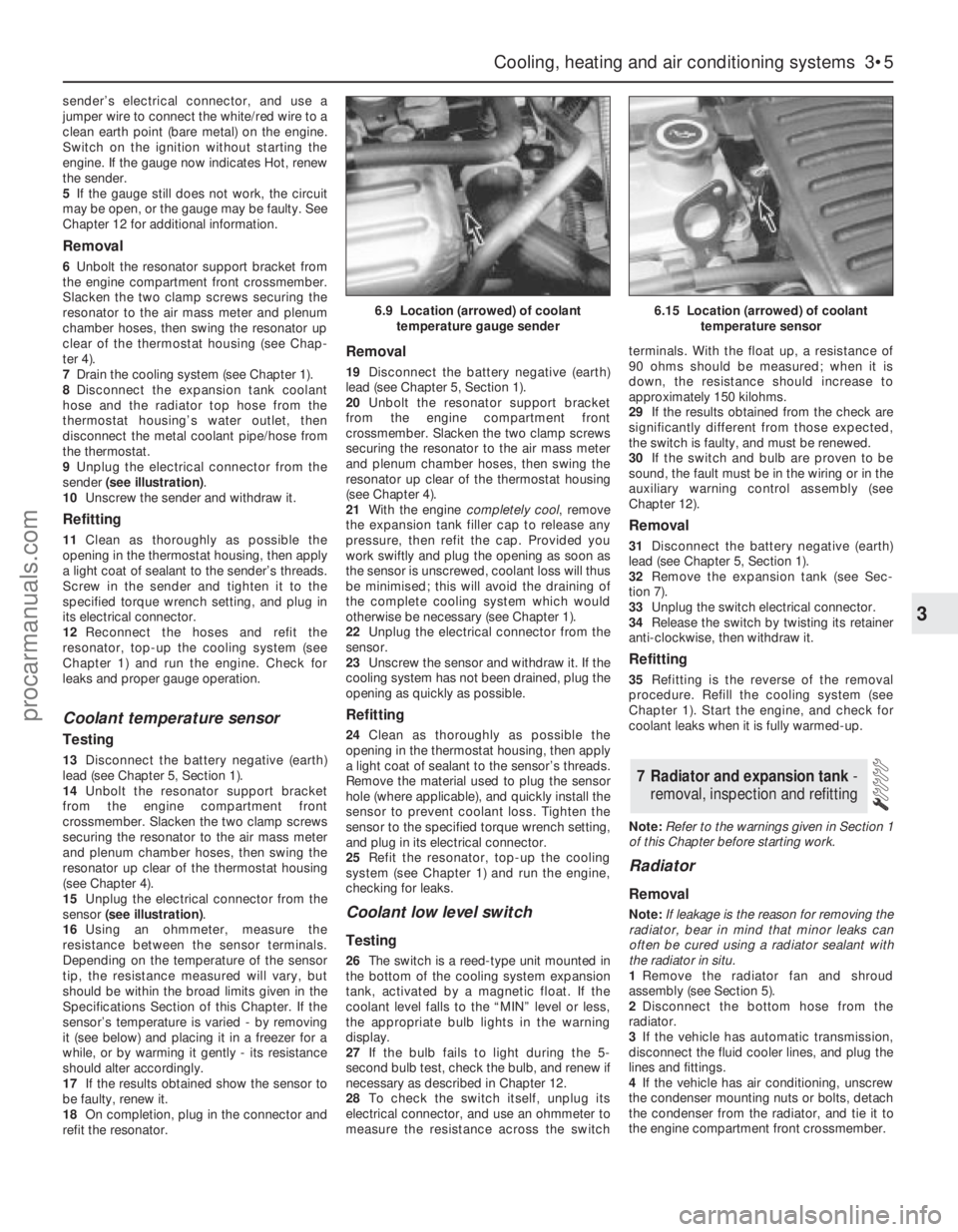
sender (see illustration).
10Unscrew the sender and withdraw it.
Refitting
11Clean as thoroughly as possible the
opening in the thermostat housing, then apply
a light coat of sealant to the sender’s threads.
Screw in the sender and tighten it to the
specified torque wrench setting, and plug in
its electrical connector.
12Reconnect the hoses and refit the
resonator, top-up the cooling system (see
Chapter 1) and run the engine. Check for
leaks and proper gauge operation.
Coolant temperature sensor
Testing
13Disconnect the battery negative (earth)
lead (see Chapter 5, Section 1).
14Unbolt the resonator support bracket
from the engine compartment front
crossmember. Slacken the two clamp screws
securing the resonator to the air mass meter
and plenum chamber hoses, then swing the
resonator up clear of the thermostat housing
(see Chapter 4).
15Unplug the electrical connector from the
sensor (see illustration).
16Using an ohmmeter, measure the
resistance between the sensor terminals.
Depending on the temperature of the sensor
tip, the resistance measured will vary, but
should be within the broad limits given in the
Specifications Section of this Chapter. If the
sensor’s temperature is varied - by removing
it (see below) and placing it in a freezer for a
while, or by warming it gently - its resistance
should alter accordingly.
17If the results obtained show the sensor to
be faulty, renew it.
18On completion, plug in the connector and
refit the resonator.
Removal
19Disconnect the battery negative (earth)
lead (see Chapter 5, Section 1).
20Unbolt the resonator support bracket
from the engine compartment front
crossmember. Slacken the two clamp screws
securing the resonator to the air mass meter
and plenum chamber hoses, then swing the
resonator up clear of the thermostat housing
(see Chapter 4).
21With the engine completely cool, remove
the expansion tank filler cap to release any
pressure, then refit the cap. Provided you
work swiftly and plug the opening as soon as
the sensor is unscrewed, coolant loss will thus
be minimised; this will avoid the draining of
the complete cooling system which would
otherwise be necessary (see Chapter 1).
22Unplug the electrical connector from the
sensor.
23Unscrew the sensor and withdraw it. If the
cooling system has not been drained, plug the
opening as quickly as possible.
Refitting
24Clean as thoroughly as possible the
opening in the thermostat housing, then apply
a light coat of sealant to the sensor’s threads.
Remove the material used to plug the sensor
hole (where applicable), and quickly install the
sensor to prevent coolant loss. Tighten the
sensor to the specified torque wrench setting,
and plug in its electrical connector.
25Refit the resonator, top-up the cooling
system (see Chapter 1) and run the engine,
checking for leaks.
Coolant low level switch
Testing
26The switch is a reed-type unit mounted in
the bottom of the cooling system expansion
tank, activated by a magnetic float. If the
coolant level falls to the “MIN” level or less,
the appropriate bulb lights in the warning
display.
27If the bulb fails to light during the 5-
second bulb test, check the bulb, and renew if
necessary as described in Chapter 12.
28To check the switch itself, unplug its
electrical connector, and use an ohmmeter to
measure the resistance across the switchterminals. With the float up, a resistance of
90 ohms should be measured; when it is
down, the resistance should increase to
approximately 150 kilohms.
29If the results obtained from the check are
significantly different from those expected,
the switch is faulty, and must be renewed.
30If the switch and bulb are proven to be
sound, the fault must be in the wiring or in the
auxiliary warning control assembly (see
Chapter 12).
Removal
31Disconnect the battery negative (earth)
lead (see Chapter 5, Section 1).
32Remove the expansion tank (see Sec-
tion 7).
33Unplug the switch electrical connector.
34Release the switch by twisting its retainer
anti-clockwise, then withdraw it.
Refitting
35Refitting is the reverse of the removal
procedure. Refill the cooling system (see
Chapter 1). Start the engine, and check for
coolant leaks when it is fully warmed-up.
Note:Refer to the warnings given in Section 1
of this Chapter before starting work.
Radiator
Removal
Note:If leakage is the reason for removing the
radiator, bear in mind that minor leaks can
often be cured using a radiator sealant with
the radiator in situ.
1Remove the radiator fan and shroud
assembly (see Section 5).
2Disconnect the bottom hose from the
radiator.
3If the vehicle has automatic transmission,
disconnect the fluid cooler lines, and plug the
lines and fittings.
4If the vehicle has air conditioning, unscrew
the condenser mounting nuts or bolts, detach
the condenser from the radiator, and tie it to
the engine compartment front crossmember.
7 Radiator and expansion tank -
removal, inspection and refitting
Cooling, heating and air conditioning systems 3•5
3
6.9 Location (arrowed) of coolant
temperature gauge sender6.15 Location (arrowed) of coolant
temperature sensor
procarmanuals.com
Page 140 of 279
back again, as an assistant depresses the
accelerator pedal. If the valve shows any sign
of stiffness, sticking or otherwise-inhibited
movement (and the accelerator cable is
known from the previous check to be in good
condition), spray the throttle linkage with
penetrating lubricant, allow time for it to work,
and repeat the check; if no improvement is
obtained, the complete throttle housing must
be renewed (Chapter 4).
15Unclip the air cleaner cover, and check
that the air filter element and the crankcase
ventilation system filter are not clogged or
soaked. (A clogged air filter will obstruct the
intake air flow, causing a noticeable effect on
engine performance; a clogged crankcase
ventilation system filter will inhibit crankcase
“breathing”). Renew or clean the filter(s) as
appropriate; refer to the relevant Sections of
Chapter 1 for further information, if required.
Before refitting the air cleaner cover, check
that the air intake (located under the front left-
hand wing, opening behind the direction
indicator/headlight assembly) is clear. It
should be possible to blow through the intake,
or to probe it (carefully) as far as the rear of
the direction indicator light.
16Start the engine and allow it to idle.
Note:Working in the engine compartment
while the engine is running requires great care
if the risk of personal injury is to be avoided;
among the dangers are burns from contact
with hot components, or contact with moving
components such as the radiator cooling fan
or the auxiliary drivebelt. Refer to “Safety
first!” at the front of this manual before
starting, and ensure that your hands, and long
hair or loose clothing, are kept well clear of hot
or moving components at all times.
17Working from the air intake junction at the
inner wing panel, via the air cleaner assembly
and air mass meter, to the resonator, plenum
chamber, throttle housing and inlet manifold
(and including the various vacuum hoses and
pipes connected to these), check for air leaks.
Usually, these will be revealed by sucking or
hissing noises, but minor leaks may be traced
by spraying a solution of soapy water on to
the suspect joint; if a leak exists, it will be
shown by the change in engine note and the
accompanying air bubbles (or sucking-in of
the liquid, depending on the pressure
difference at that point). If a leak is found at
any point, tighten the fastening clamp and/or
renew the faulty components, as applicable.
18Similarly, work from the cylinder head, via
the manifold (and not forgetting the related
EGR and pulse-air system components) to the
tailpipe, to check that the exhaust system is
free from leaks. The simplest way of doing
this, if the vehicle can be raised and
supported safely and with complete security
while the check is made, is to temporarily
block the tailpipe while listening for the sound
of escaping exhaust gases; any leak should
be evident. If a leak is found at any point,
tighten the fastening clamp bolts and/or nuts,
renew the gasket, and/or renew the faultysection of the system, as necessary, to seal
the leak.
19It is possible to make a further check of
the electrical connections by wiggling each
electrical connector of the system in turn as
the engine is idling; a faulty connector will be
immediately evident from the engine’s
response as contact is broken and remade. A
faulty connector should be renewed to ensure
the future reliability of the system; note that
this may mean the renewal of that entire
section of the loom - see your local Ford
dealer for details.
20Switch off the engine. If the fault is not yet
identified, the next step is to check the
ignition voltages, using an engine analyser
with an oscilloscope - without such
equipment, the only tests possible are to
remove and check each spark plug in turn, to
check the spark plug (HT) lead connections
and resistances, and to check the
connections and resistances of the ignition
coil. Refer to the relevant Sections of
Chapters 1 and 5.
21The final step in these preliminary checks
would be to use an exhaust gas analyser to
measure the CO level at the exhaust tailpipe.This check cannot be made without special
test equipment - see your local Ford dealer for
details.
Fault code read-out
22As noted in the general comments at the
beginning of this Section, the preliminary
checks outlined above should eliminate the
majority of faults from the engine
management system. If the fault is not yet
identified, the next step is to connect a fault
code reader to the ECU, so that its self-
diagnosis facility can be used to identify the
faulty part of the system; further tests can
then be made to identify the exact cause of
the fault.
23In their basic form, fault code readers are
simply hand-held electronic devices, which
take data stored within an ECU’s memory and
display it when required as two- or three-digit
fault codes. The more sophisticated versions
now available can also control sensors and
actuators, to provide more effective testing;
some can store information, so that a road
test can be carried out, and any faults
encountered during the test can be displayed
afterwards.
6•6 Emissions control systems
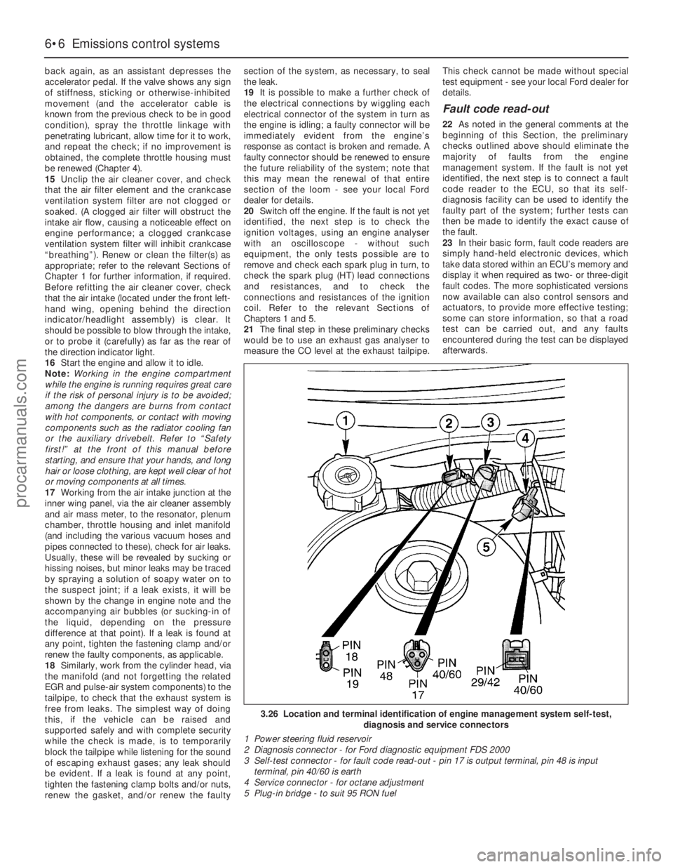
3.26 Location and terminal identification of engine management system self-test,
diagnosis and service connectors
1 Power steering fluid reservoir
2 Diagnosis connector - for Ford diagnostic equipment FDS 2000
3 Self-test connector - for fault code read-out - pin 17 is output terminal, pin 48 is input
terminal, pin 40/60 is earth
4 Service connector - for octane adjustment
5 Plug-in bridge - to suit 95 RON fuel
procarmanuals.com
Page 141 of 279
24Ford specify the use of their STAR (Self-
Test Automatic Readout) tester; most Ford
dealers should have such equipment, and the
staff trained to use it effectively. The only
alternatives are as follows:
(a) To obtain one of those proprietary readers
which can interpret EEC-IV three-digit
codes - at present, such readers are too
expensive for the DIY enthusiast, but are
becoming more popular with smaller
specialist garages.
(b) To use an analogue voltmeter, whereby
the stored codes are displayed as sweeps
of the voltmeter needle. This option limits
the operator to a read-out of any codes
stored - ie, there is no control of sensors
and/or actuators - but can still be useful in
pinpointing the faulty part of the engine
management system. The display is
interpreted as follows. Each code
(whether fault code or
command/separator) is marked by a
three-to-four second pause - code “538”
would therefore be shown as long (3 to
4 seconds) pause, five fast sweeps of the
needle, slight (1 second) pause, three fast
sweeps, slight pause, eight fast sweeps,
long pause.
(c) Owners without access to such
equipment must take the vehicle to a Ford
dealer, or to an expert who has similar
equipment and the skill to use it.
25Because of the variations in the design of
fault code readers, it is not possible to give
exact details of the sequence of tests; the
manufacturer’s instructions must be followed,
in conjunction with the codes given below.
The following ten paragraphs outline the
procedure to be followed using a version of
the Ford STAR tester, to illustrate the general
principles, as well as notes to guide the owner
using only a voltmeter.
26The vehicle must be prepared by applying
the handbrake, switching off the air
conditioning (where fitted) and any other
electrical loads (lights, heated rear window,
etc), then selecting neutral (manual
transmission) or the “P” position (automatic
transmission). Where the engine is required to
be running, it must be fully warmed-up to
normal operating temperature before the test
is started. Using any adaptors required,
connect the fault code reader to the system
via the (triangular, three-pin) self-test
connector on the right-hand end of the engine
compartment bulkhead (see illustration). If a
voltmeter is being used, connect its positive
lead to the battery positive terminal, and its
negative lead to the self-test connector’s
output terminal, pin 17. Have a pen and paper
ready to write down the codes displayed.
27Set the tester in operation. For the Ford
STAR tester, a display check will be carried
out and the test mode requirements must be
entered. If a voltmeter is being used, connect
a spare length of wire to earth the self-test
connector’s input terminal, pin 48. Be very
careful to ensure that you earth the correctterminal - the one with the white/green wire.
The first part of the test starts, with the
ignition switched on, but with the engine off.
On pressing the “Mem/test” button, the tester
displays “TEST” and the ready code “000”,
followed by a command code “010” - the
accelerator pedal must be fully depressed
within 10 seconds of the command code
appearing, or fault codes “576” or “577” will
appear when they are called up later. If a
voltmeter is being used, code “000” will not
appear (except perhaps as a flicker of the
needle) and “010” will appear as a single
sweep - to ensure correct interpretation of the
display, watch carefully for the interval
between the end of one code and the
beginning of the next, otherwise you will
become confused and misinterpret the read-
out.
28The tester will then display the codes for
any faults in the system at the time of the test.
Each code is repeated once; if no faults are
present, code “111” will be displayed. If a
voltmeter is being used, the pause between
repetitions will vary according to the
equipment in use and the number of faults in
the system, but was found to be
approximately 3 to 4 seconds - it may be
necessary to start again, and to repeat the
read-out until you are familiar with what you
are seeing.
29Next the tester will display code “010”
(now acting as a separator), followed by the
codes for any faults stored in the ECU’s
memory; if no faults were stored, code “111”
will be displayed.
30When prompted by the tester, the
operator must next depress the accelerator
pedal fully; the tester then checks several
actuators. Further test modes include a
“wiggle test” facility, whereby the operator
can check the various connectors as
described in paragraph 19 above (in this case,
any fault will be logged and the appropriate
code will be displayed), a facility for recalling
codes displayed, and a means for clearing the
ECU’s memory at the end of the test
procedure when any faults have been
rectified.
31The next step when using the Ford STAR
tester is to conduct a test with the engine
running. With the tester set in operation (see
paragraph 26 above) the engine is started and
allowed to idle. On pressing the “Mem/test”
button, the tester displays “TEST”, followed
by one of two codes, as follows.
32If warning code “998” appears, followed
by the appropriate fault code, switch off and
check as indicated the coolant temperature
sensor, the intake air temperature sensor, the
air mass meter, the throttle potentiometer
and/or their related circuits, then restart the
test procedure.
33If command code “020” appears, carry
out the following procedure within ten
seconds:
(a) Depress the brake pedal fully.
(b) Turn the steering to full-lock (either way)and centre it again, to produce a signal
from the power steering pressure switch -
if no signal is sent, fault code “521” will
be displayed.
(c) If automatic transmission is fitted, switch
the overdrive cancel button on and off,
then do the same for the
“Economy/Sport” mode switch.
(d) Wait for separator code “010” to be
displayed, then within 10 seconds,
depress the accelerator pedal fully,
increasing engine speed rapidly above
3000 rpm - release the pedal.
34Any faults found in the system will be
logged and displayed. Each code is repeated
once; if no faults are present, code “111” will
be displayed.
35When the codes have been displayed for
all faults logged, the ECU enters its “Service
Adjustment Programme”, as follows:
(a) The programme lasts for 2 minutes.
(b) The idle speed control valve is
deactivated, and the idle speed is set to
its pre-programmed (unregulated) value. If
the appropriate equipment is connected,
the base idle speed can be checked
(note, however, that it is not adjustable).
(c) The ignition timing can be checked if a
timing light is connected (note, however,
that it is not adjustable).
(d) Pressing the accelerator pedal fully at any
time during this period will execute a
cylinder balance test. Each injector in turn
is switched off, and the corresponding
decrease in engine speed is logged -
code “090” will be displayed if the test is
successful.
(e) At the end of the 2 minutes, the
completion of the programme is shown
by the engine speed briefly rising, then
returning to normal idling speed as
the idle speed control valve is
reactivated.
36As with the engine-off test, further test
modes include a “wiggle test” facility,
whereby the operator can check the various
connectors as described in paragraph 19
above (in this case, any fault will be logged
and the appropriate code will be displayed), a
facility for recalling codes displayed, and a
means for clearing the ECU’s memory at the
end of the test procedure when any faults
have been rectified. If equipment other than
the Ford STAR tester is used, the ECU’s
memory can be cleared by disconnecting the
battery - if this is not done, the code will
reappear with any other codes in the event of
subsequent trouble, but remember that other
systems with memory (such as the clock and
audio equipment) will also be affected. Should
it become necessary to disconnect the
battery during work on any other part of the
vehicle, first check to see if any fault codes
have been logged.
37Given overleaf are the possible codes,
their meanings, and where relevant, the action
to be taken as a result of a code being
displayed.
Emissions control systems 6•7
6
procarmanuals.com
Page 200 of 279
Removal
1Disconnect the battery negative (earth) lead
(Chapter 5, Section 1).
2Remove the windscreen wiper arms
(Chapter 12), then remove the cowl from just
in front of the windscreen. The cowl is in two
sections, with retaining screws located along
its front edge. With the cowl removed,
disconnect the speedometer cable by pulling
it from the intermediate inner cable extension.
3Remove the centre console (Section 30),
then unscrew the screws and remove the
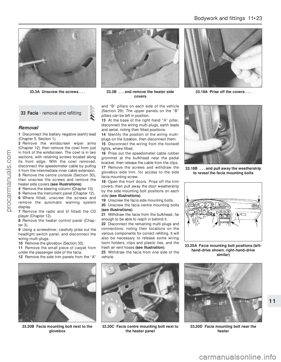
heater side covers (see illustrations).
4Remove the steering column (Chapter 10).
5Remove the instrument panel (Chapter 12).
6Where fitted, unscrew the screws and
remove the automatic warning system
display.
7Remove the radio and (if fitted) the CD
player (Chapter 12).
8Remove the heater control panel (Chap-
ter 3).
9Using a screwdriver, carefully prise out the
headlight switch panel, and disconnect the
wiring multi-plugs.
10Remove the glovebox (Section 32).
11Remove the small piece of carpet from
under the passenger side of the facia.
12Remove the side trim panels from the “A”and “B” pillars on each side of the vehicle
(Section 29). The upper panels on the “B”
pillars can be left in position.
13At the base of the right-hand “A” pillar,
disconnect the wiring multi-plugs, earth leads
and aerial, noting their fitted positions.
14Identify the position of the wiring multi-
plugs on the fusebox, then disconnect them.
15Disconnect the wiring from the footwell
lights, where fitted.
16Prise out the speedometer cable rubber
grommet at the bulkhead near the pedal
bracket, then release the cable from the clips.
17Remove the screws and withdraw the
glovebox side trim, for access to the side
facia mounting screw.
18Open the front doors. Prise off the trim
covers, then pull away the door weatherstrip
by the side mounting bolt positions on each
side (see illustrations).
19Unscrew the facia side mounting bolts.
20Unscrew the facia centre mounting bolts
(see illustrations).
21Withdraw the facia from the bulkhead, far
enough to be able to reach in behind it.
22Disconnect the remaining multi-plugs and
connections, noting their locations on the
various components for correct refitting. It will
also be necessary to release some wiring
loom holders, clips and plastic ties, and the
fresh air vent hoses (see illustration).
23Withdraw the facia from one side of the
vehicle.
33 Facia - removal and refitting
Bodywork and fittings 11•23
11
33.20B Facia mounting bolt next to the
glovebox33.20C Facia centre mounting bolt next to
the heater panel33.20D Facia mounting bolt near the
heater
33.3A Unscrew the screws . . .33.3B . . . and remove the heater side
covers33.18A Prise off the covers . . .
33.18B . . . and pull away the weatherstrip
to reveal the facia mounting bolts
33.20A Facia mounting bolt positions (left-
hand-drive shown, right-hand-drive
similar)
procarmanuals.com
Page 215 of 279
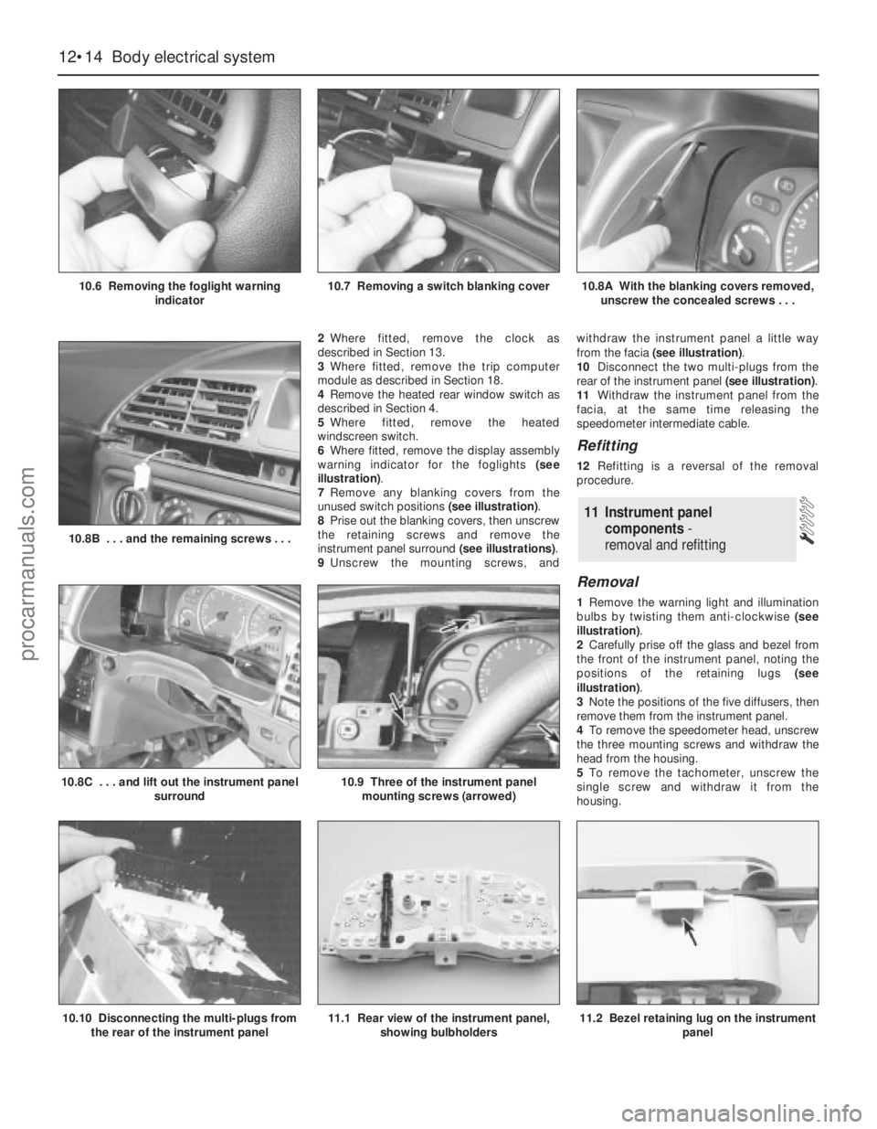
2Where fitted, remove the clock as
described in Section 13.
3Where fitted, remove the trip computer
module as described in Section 18.
4Remove the heated rear window switch as
described in Section 4.
5Where fitted, remove the heated
windscreen switch.
6Where fitted, remove the display assembly
warning indicator for the foglights (see
illustration).
7Remove any blanking covers from the
unused switch positions (see illustration).
8Prise out the blanking covers, then unscrew
the retaining screws and remove the
instrument panel surround (see illustrations).
9Unscrew the mounting screws, andwithdraw the instrument panel a little way
from the facia (see illustration).
10Disconnect the two multi-plugs from the
rear of the instrument panel (see illustration).
11Withdraw the instrument panel from the
facia, at the same time releasing the
speedometer intermediate cable.
Refitting
12Refitting is a reversal of the removal
procedure.
Removal
1Remove the warning light and illumination
bulbs by twisting them anti-clockwise (see
illustration).
2Carefully prise off the glass and bezel from
the front of the instrument panel, noting the
positions of the retaining lugs (see
illustration).
3Note the positions of the five diffusers, then
remove them from the instrument panel.
4To remove the speedometer head, unscrew
the three mounting screws and withdraw the
head from the housing.
5To remove the tachometer, unscrew the
single screw and withdraw it from the
housing.
11 Instrument panel
components-
removal and refitting
12•14 Body electrical system
10.6 Removing the foglight warning
indicator10.7 Removing a switch blanking cover10.8A With the blanking covers removed,
unscrew the concealed screws . . .
10.10 Disconnecting the multi-plugs from
the rear of the instrument panel11.1 Rear view of the instrument panel,
showing bulbholders11.2 Bezel retaining lug on the instrument
panel
10.8C . . . and lift out the instrument panel
surround10.9 Three of the instrument panel
mounting screws (arrowed)
10.8B . . . and the remaining screws . . .
procarmanuals.com
Page 218 of 279
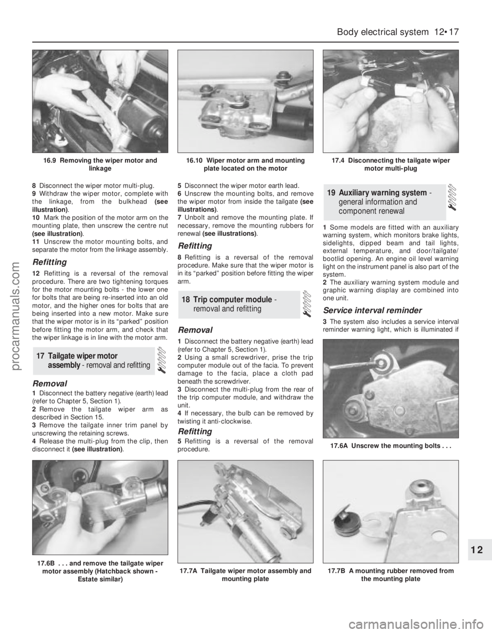
8Disconnect the wiper motor multi-plug.
9Withdraw the wiper motor, complete with
the linkage, from the bulkhead (see
illustration).
10Mark the position of the motor arm on the
mounting plate, then unscrew the centre nut
(see illustration).
11Unscrew the motor mounting bolts, and
separate the motor from the linkage assembly.
Refitting
12Refitting is a reversal of the removal
procedure. There are two tightening torques
for the motor mounting bolts - the lower one
for bolts that are being re-inserted into an old
motor, and the higher ones for bolts that are
being inserted into a new motor. Make sure
that the wiper motor is in its “parked” position
before fitting the motor arm, and check that
the wiper linkage is in line with the motor arm.
Removal
1Disconnect the battery negative (earth) lead
(refer to Chapter 5, Section 1).
2Remove the tailgate wiper arm as
described in Section 15.
3Remove the tailgate inner trim panel by
unscrewing the retaining screws.
4Release the multi-plug from the clip, then
disconnect it (see illustration).5Disconnect the wiper motor earth lead.
6Unscrew the mounting bolts, and remove
the wiper motor from inside the tailgate (see
illustrations).
7Unbolt and remove the mounting plate. If
necessary, remove the mounting rubbers for
renewal (see illustrations).
Refitting
8Refitting is a reversal of the removal
procedure. Make sure that the wiper motor is
in its “parked” position before fitting the wiper
arm.
Removal
1Disconnect the battery negative (earth) lead
(refer to Chapter 5, Section 1).
2Using a small screwdriver, prise the trip
computer module out of the facia. To prevent
damage to the facia, place a cloth pad
beneath the screwdriver.
3Disconnect the multi-plug from the rear of
the trip computer module, and withdraw the
unit.
4If necessary, the bulb can be removed by
twisting it anti-clockwise.
Refitting
5Refitting is a reversal of the removal
procedure.1Some models are fitted with an auxiliary
warning system, which monitors brake lights,
sidelights, dipped beam and tail lights,
external temperature, and door/tailgate/
bootlid opening. An engine oil level warning
light on the instrument panel is also part of the
system.
2The auxiliary warning system module and
graphic warning display are combined into
one unit.
Service interval reminder
3The system also includes a service interval
reminder warning light, which is illuminated if
19 Auxiliary warning system -
general information and
component renewal
18 Trip computer module-
removal and refitting
17 Tailgate wiper motor
assembly - removal and refitting
Body electrical system 12•17
12
17.6B . . . and remove the tailgate wiper
motor assembly (Hatchback shown -
Estate similar)17.7A Tailgate wiper motor assembly and
mounting plate17.7B A mounting rubber removed from
the mounting plate
17.6A Unscrew the mounting bolts . . .
16.9 Removing the wiper motor and
linkage16.10 Wiper motor arm and mounting
plate located on the motor17.4 Disconnecting the tailgate wiper
motor multi-plug
procarmanuals.com
Page 219 of 279
the specified mileage (or time) since the last
service has been reached.
4To reset the service interval system and
turn off the light, a switch inside the glovebox
must be depressed for a minimum of 4
seconds with the ignition switched on. This
should be carried out by a Ford dealer if the
vehicle is still in the warranty period.
Component renewal
5The following paragraphs describe brief
removal procedures for the auxiliary warning
system components. Disconnect the battery
negative (earth) lead before commencing
work (refer to Chapter 5, Section 1). Refitting
procedures are a reversal of removal.
Display warning bulb
6Remove the control assembly.
7Prise off the cover, and pull out the relevant
bulb and bulbholder.
Low air temperature warning sender
unit
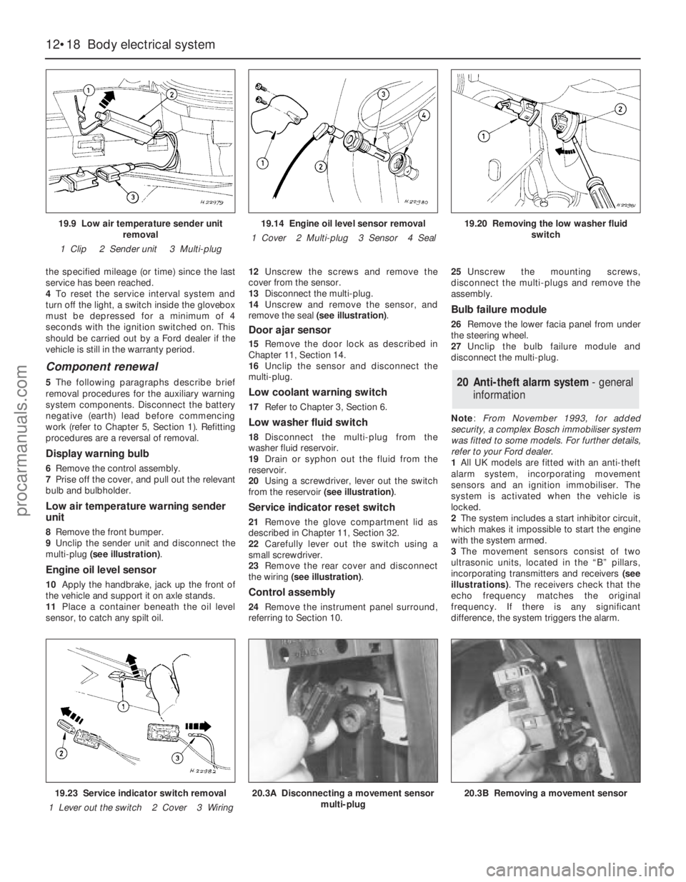
8Remove the front bumper.
9Unclip the sender unit and disconnect the
multi-plug (see illustration).
Engine oil level sensor
10Apply the handbrake, jack up the front of
the vehicle and support it on axle stands.
11Place a container beneath the oil level
sensor, to catch any spilt oil.12Unscrew the screws and remove the
cover from the sensor.
13Disconnect the multi-plug.
14Unscrew and remove the sensor, and
remove the seal (see illustration).
Door ajar sensor
15Remove the door lock as described in
Chapter 11, Section 14.
16Unclip the sensor and disconnect the
multi-plug.
Low coolant warning switch
17Refer to Chapter 3, Section 6.
Low washer fluid switch
18Disconnect the multi-plug from the
washer fluid reservoir.
19Drain or syphon out the fluid from the
reservoir.
20Using a screwdriver, lever out the switch
from the reservoir (see illustration).
Service indicator reset switch
21Remove the glove compartment lid as
described in Chapter 11, Section 32.
22Carefully lever out the switch using a
small screwdriver.
23Remove the rear cover and disconnect
the wiring (see illustration).
Control assembly
24Remove the instrument panel surround,
referring to Section 10.25Unscrew the mounting screws,
disconnect the multi-plugs and remove the
assembly.
Bulb failure module
26Remove the lower facia panel from under
the steering wheel.
27Unclip the bulb failure module and
disconnect the multi-plug.
Note: From November 1993, for added
security, a complex Bosch immobiliser system
was fitted to some models. For further details,
refer to your Ford dealer.
1All UK models are fitted with an anti-theft
alarm system, incorporating movement
sensors and an ignition immobiliser. The
system is activated when the vehicle is
locked.
2The system includes a start inhibitor circuit,
which makes it impossible to start the engine
with the system armed.
3The movement sensors consist of two
ultrasonic units, located in the “B” pillars,
incorporating transmitters and receivers (see
illustrations). The receivers check that the
echo frequency matches the original
frequency. If there is any significant
difference, the system triggers the alarm.
20 Anti-theft alarm system- general
information
12•18 Body electrical system
19.9 Low air temperature sender unit
removal
1 Clip 2 Sender unit 3 Multi-plug19.14 Engine oil level sensor removal
1 Cover 2 Multi-plug 3 Sensor 4 Seal19.20 Removing the low washer fluid
switch
19.23 Service indicator switch removal
1 Lever out the switch 2 Cover 3 Wiring20.3A Disconnecting a movement sensor
multi-plug20.3B Removing a movement sensor
procarmanuals.com
Page 274 of 279
REF•15Glossary of Technical Terms
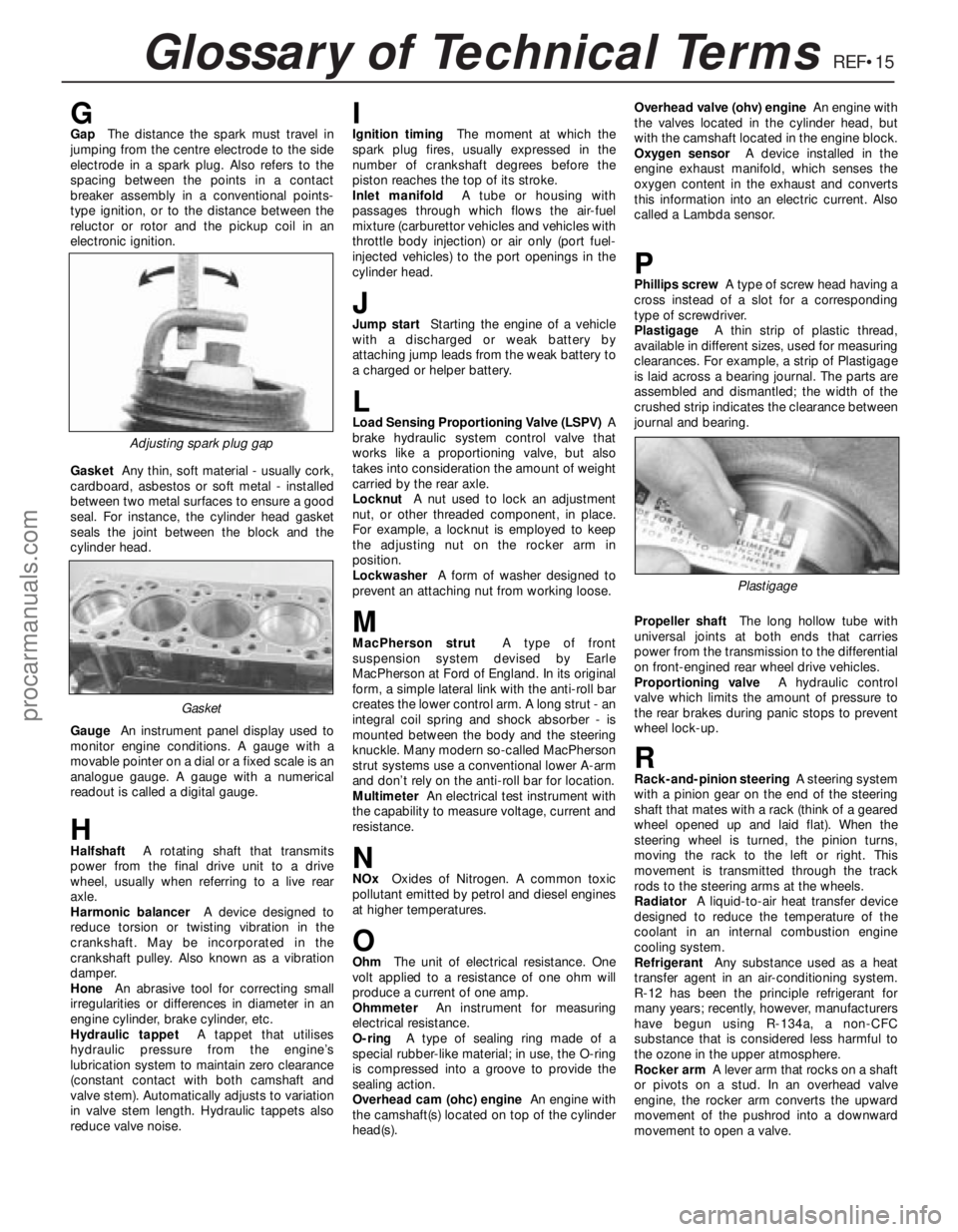
GGapThe distance the spark must travel in
jumping from the centre electrode to the side
electrode in a spark plug. Also refers to the
spacing between the points in a contact
breaker assembly in a conventional points-
type ignition, or to the distance between the
reluctor or rotor and the pickup coil in an
electronic ignition.
GasketAny thin, soft material - usually cork,
cardboard, asbestos or soft metal - installed
between two metal surfaces to ensure a good
seal. For instance, the cylinder head gasket
seals the joint between the block and the
cylinder head.
GaugeAn instrument panel display used to
monitor engine conditions. A gauge with a
movable pointer on a dial or a fixed scale is an
analogue gauge. A gauge with a numerical
readout is called a digital gauge.
HHalfshaftA rotating shaft that transmits
power from the final drive unit to a drive
wheel, usually when referring to a live rear
axle.
Harmonic balancerA device designed to
reduce torsion or twisting vibration in the
crankshaft. May be incorporated in the
crankshaft pulley. Also known as a vibration
damper.
HoneAn abrasive tool for correcting small
irregularities or differences in diameter in an
engine cylinder, brake cylinder, etc.
Hydraulic tappetA tappet that utilises
hydraulic pressure from the engine’s
lubrication system to maintain zero clearance
(constant contact with both camshaft and
valve stem). Automatically adjusts to variation
in valve stem length. Hydraulic tappets also
reduce valve noise.
IIgnition timingThe moment at which the
spark plug fires, usually expressed in the
number of crankshaft degrees before the
piston reaches the top of its stroke.
Inlet manifoldA tube or housing with
passages through which flows the air-fuel
mixture (carburettor vehicles and vehicles with
throttle body injection) or air only (port fuel-
injected vehicles) to the port openings in the
cylinder head.
JJump startStarting the engine of a vehicle
with a discharged or weak battery by
attaching jump leads from the weak battery to
a charged or helper battery.
LLoad Sensing Proportioning Valve (LSPV)A
brake hydraulic system control valve that
works like a proportioning valve, but also
takes into consideration the amount of weight
carried by the rear axle.
LocknutA nut used to lock an adjustment
nut, or other threaded component, in place.
For example, a locknut is employed to keep
the adjusting nut on the rocker arm in
position.
LockwasherA form of washer designed to
prevent an attaching nut from working loose.
MMacPherson strutA type of front
suspension system devised by Earle
MacPherson at Ford of England. In its original
form, a simple lateral link with the anti-roll bar
creates the lower control arm. A long strut - an
integral coil spring and shock absorber - is
mounted between the body and the steering
knuckle. Many modern so-called MacPherson
strut systems use a conventional lower A-arm
and don’t rely on the anti-roll bar for location.
MultimeterAn electrical test instrument with
the capability to measure voltage, current and
resistance.
NNOxOxides of Nitrogen. A common toxic
pollutant emitted by petrol and diesel engines
at higher temperatures.
OOhmThe unit of electrical resistance. One
volt applied to a resistance of one ohm will
produce a current of one amp.
OhmmeterAn instrument for measuring
electrical resistance.
O-ringA type of sealing ring made of a
special rubber-like material; in use, the O-ring
is compressed into a groove to provide the
sealing action.
Overhead cam (ohc) engineAn engine with
the camshaft(s) located on top of the cylinder
head(s).Overhead valve (ohv) engineAn engine with
the valves located in the cylinder head, but
with the camshaft located in the engine block.
Oxygen sensorA device installed in the
engine exhaust manifold, which senses the
oxygen content in the exhaust and converts
this information into an electric current. Also
called a Lambda sensor.
PPhillips screwA type of screw head having a
cross instead of a slot for a corresponding
type of screwdriver.
PlastigageA thin strip of plastic thread,
available in different sizes, used for measuring
clearances. For example, a strip of Plastigage
is laid across a bearing journal. The parts are
assembled and dismantled; the width of the
crushed strip indicates the clearance between
journal and bearing.
Propeller shaftThe long hollow tube with
universal joints at both ends that carries
power from the transmission to the differential
on front-engined rear wheel drive vehicles.
Proportioning valveA hydraulic control
valve which limits the amount of pressure to
the rear brakes during panic stops to prevent
wheel lock-up.
RRack-and-pinion steeringA steering system
with a pinion gear on the end of the steering
shaft that mates with a rack (think of a geared
wheel opened up and laid flat). When the
steering wheel is turned, the pinion turns,
moving the rack to the left or right. This
movement is transmitted through the track
rods to the steering arms at the wheels.
RadiatorA liquid-to-air heat transfer device
designed to reduce the temperature of the
coolant in an internal combustion engine
cooling system.
RefrigerantAny substance used as a heat
transfer agent in an air-conditioning system.
R-12 has been the principle refrigerant for
many years; recently, however, manufacturers
have begun using R-134a, a non-CFC
substance that is considered less harmful to
the ozone in the upper atmosphere.
Rocker armA lever arm that rocks on a shaft
or pivots on a stud. In an overhead valve
engine, the rocker arm converts the upward
movement of the pushrod into a downward
movement to open a valve.
Adjusting spark plug gap
Plastigage
Gasket
procarmanuals.com