1993 FORD MONDEO clock reset
[x] Cancel search: clock resetPage 53 of 279
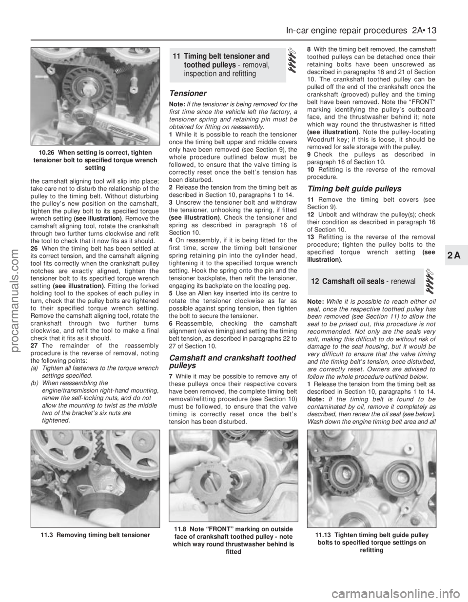
the camshaft aligning tool will slip into place;
take care not to disturb the relationship of the
pulley to the timing belt. Without disturbing
the pulley’s new position on the camshaft,
tighten the pulley bolt to its specified torque
wrench setting (see illustration). Remove the
camshaft aligning tool, rotate the crankshaft
through two further turns clockwise and refit
the tool to check that it now fits as it should.
26When the timing belt has been settled at
its correct tension, and the camshaft aligning
tool fits correctly when the crankshaft pulley
notches are exactly aligned, tighten the
tensioner bolt to its specified torque wrench
setting (see illustration). Fitting the forked
holding tool to the spokes of each pulley in
turn, check that the pulley bolts are tightened
to their specified torque wrench setting.
Remove the camshaft aligning tool, rotate the
crankshaft through two further turns
clockwise, and refit the tool to make a final
check that it fits as it should.
27The remainder of the reassembly
procedure is the reverse of removal, noting
the following points:
(a) Tighten all fasteners to the torque wrench
settings specified.
(b) When reassembling the
engine/transmission right-hand mounting,
renew the self-locking nuts, and do not
allow the mounting to twist as the middle
two of the bracket’s six nuts are
tightened.
Tensioner
Note:If the tensioner is being removed for the
first time since the vehicle left the factory, a
tensioner spring and retaining pin must be
obtained for fitting on reassembly.
1While it is possible to reach the tensioner
once the timing belt upper and middle covers
only have been removed (see Section 9), the
whole procedure outlined below must be
followed, to ensure that the valve timing is
correctly reset once the belt’s tension has
been disturbed.
2Release the tension from the timing belt as
described in Section 10, paragraphs 1 to 14.
3Unscrew the tensioner bolt and withdraw
the tensioner, unhooking the spring, if fitted
(see illustration). Check the tensioner and
spring as described in paragraph 16 of
Section 10.
4On reassembly, if it is being fitted for the
first time, screw the timing belt tensioner
spring retaining pin into the cylinder head,
tightening it to the specified torque wrench
setting. Hook the spring onto the pin and the
tensioner backplate, then refit the tensioner,
engaging its backplate on the locating peg.
5Use an Allen key inserted into its centre to
rotate the tensioner clockwise as far as
possible against spring tension, then tighten
the bolt to secure the tensioner.
6Reassemble, checking the camshaft
alignment (valve timing) and setting the timing
belt tension, as described in paragraphs 22 to
27 of Section 10.
Camshaft and crankshaft toothed
pulleys
7While it may be possible to remove any of
these pulleys once their respective covers
have been removed, the complete timing belt
removal/refitting procedure (see Section 10)
must be followed, to ensure that the valve
timing is correctly reset once the belt’s
tension has been disturbed.8With the timing belt removed, the camshaft
toothed pulleys can be detached once their
retaining bolts have been unscrewed as
described in paragraphs 18 and 21 of Section
10. The crankshaft toothed pulley can be
pulled off the end of the crankshaft once the
crankshaft (grooved) pulley and the timing
belt have been removed. Note the “FRONT”
marking identifying the pulley’s outboard
face, and the thrustwasher behind it; note
which way round the thrustwasher is fitted
(see illustration). Note the pulley-locating
Woodruff key; if this is loose, it should be
removed for safe storage with the pulley.
9Check the pulleys as described in
paragraph 16 of Section 10.
10Refitting is the reverse of the removal
procedure.
Timing belt guide pulleys
11Remove the timing belt covers (see
Section 9).
12Unbolt and withdraw the pulley(s); check
their condition as described in paragraph 16
of Section 10.
13Refitting is the reverse of the removal
procedure; tighten the pulley bolts to the
specified torque wrench setting (see
illustration).
Note:While it is possible to reach either oil
seal, once the respective toothed pulley has
been removed (see Section 11) to allow the
seal to be prised out, this procedure is not
recommended. Not only are the seals very
soft, making this difficult to do without risk of
damage to the seal housing, but it would be
very difficult to ensure that the valve timing
and the timing belt’s tension, once disturbed,
are correctly reset. Owners are advised to
follow the whole procedure outlined below.
1Release the tension from the timing belt as
described in Section 10, paragraphs 1 to 14.
Note:If the timing belt is found to be
contaminated by oil, remove it completely as
described, then renew the oil seal (see below).
Wash down the engine timing belt area and all
12 Camshaft oil seals - renewal
11 Timing belt tensioner and
toothed pulleys - removal,
inspection and refitting
In-car engine repair procedures 2A•13
2A
11.3 Removing timing belt tensioner11.8 Note “FRONT” marking on outside
face of crankshaft toothed pulley - note
which way round thrustwasher behind is
fitted11.13 Tighten timing belt guide pulley
bolts to specified torque settings on
refitting
10.26 When setting is correct, tighten
tensioner bolt to specified torque wrench
setting
procarmanuals.com
Page 177 of 279
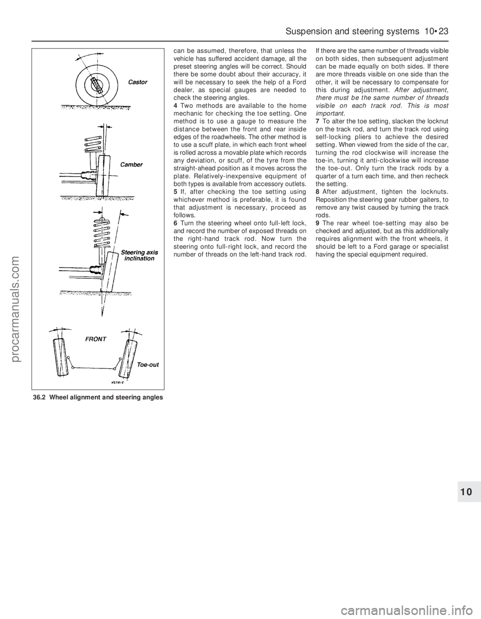
can be assumed, therefore, that unless the
vehicle has suffered accident damage, all the
preset steering angles will be correct. Should
there be some doubt about their accuracy, it
will be necessary to seek the help of a Ford
dealer, as special gauges are needed to
check the steering angles.
4Two methods are available to the home
mechanic for checking the toe setting. One
method is to use a gauge to measure the
distance between the front and rear inside
edges of the roadwheels. The other method is
to use a scuff plate, in which each front wheel
is rolled across a movable plate which records
any deviation, or scuff, of the tyre from the
straight-ahead position as it moves across the
plate. Relatively-inexpensive equipment of
both types is available from accessory outlets.
5If, after checking the toe setting using
whichever method is preferable, it is found
that adjustment is necessary, proceed as
follows.
6Turn the steering wheel onto full-left lock,
and record the number of exposed threads on
the right-hand track rod. Now turn the
steering onto full-right lock, and record the
number of threads on the left-hand track rod.If there are the same number of threads visible
on both sides, then subsequent adjustment
can be made equally on both sides. If there
are more threads visible on one side than the
other, it will be necessary to compensate for
this during adjustment. After adjustment,
there must be the same number of threads
visible on each track rod. This is most
important.
7To alter the toe setting, slacken the locknut
on the track rod, and turn the track rod using
self-locking pliers to achieve the desired
setting. When viewed from the side of the car,
turning the rod clockwise will increase the
toe-in, turning it anti-clockwise will increase
the toe-out. Only turn the track rods by a
quarter of a turn each time, and then recheck
the setting.
8After adjustment, tighten the locknuts.
Reposition the steering gear rubber gaiters, to
remove any twist caused by turning the track
rods.
9The rear wheel toe-setting may also be
checked and adjusted, but as this additionally
requires alignment with the front wheels, it
should be left to a Ford garage or specialist
having the special equipment required.
Suspension and steering systems 10•23
10
36.2 Wheel alignment and steering angles
procarmanuals.com
Page 214 of 279
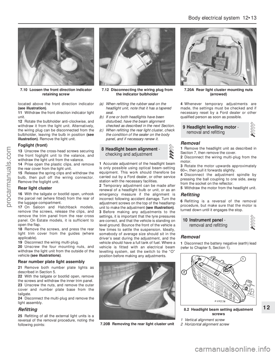
located above the front direction indicator
(see illustration).
11Withdraw the front direction indicator light
unit.
12Rotate the bulbholder anti-clockwise, and
withdraw it from the light unit. Alternatively,
the wiring plug can be disconnected from the
bulbholder, leaving the bulb in position (see
illustration). Remove the light unit.
Foglight (front)
13Unscrew the cross-head screws securing
the front foglight unit to the valance, and
withdraw the light unit from the valance.
14Prise open the plastic clips, and remove
the rear cover from the light unit.
15Release the spring clips and withdraw the
bulb, then pull off the wiring connector.
Remove the foglight unit.
Rear light cluster
16With the tailgate or bootlid open, unhook
the parcel net (where fitted) from the rear of
the luggage compartment.
17On Saloon and Hatchback models,
remove the screws, release the clips, and
remove the trim panel from the rear cross
panel. On Estate models, it is sufficient to
open the flap.
18Remove the screws, and press the rear
light trim cover from the guides (where
applicable).
19Disconnect the wiring multi-plug.
20Unscrew the four mounting nuts, and
withdraw the light unit from the outside of the
vehicle (see illustrations).
Rear number plate light assembly
21Remove both number plate lights as
described in Section 5.
22With the tailgate or bootlid open, remove
the screws and withdraw the inner trim panel.
23Unscrew the nuts, and remove the outer
cover and number plate base from the
tailgate.
24Disconnect the multi-plug and remove the
light assembly.
Refitting
25Refitting of all the external light units is a
reversal of the removal procedure, noting the
following points:(a) When refitting the rubber seal on the
headlight unit, note that it has a tapered
seat.
(b) If one or both headlights have been
disturbed, have the beam alignment
checked as described in the next Section.
(c) When refitting the rear light cluster, check
the condition of the sealer on the body
panel, and if necessary renew it.
1Accurate adjustment of the headlight beam
is only possible using optical beam-setting
equipment. This work should therefore be
carried out by a Ford dealer, or other service
station with the necessary facilities.
2Temporary adjustment can be made after
renewal of a headlight bulb or unit, or as an
emergency measure if the alignment is
incorrect following accident damage. Turn the
adjustment screws on the top of the headlamp
unit to make the adjustment (see illustration).
3Before making any adjustments to the
settings, it is important that the tyre pressures
are correct, and that the vehicle is standing on
level ground. Bounce the front of the vehicle a
few times to settle the suspension. Ideally,
somebody of average size should sit in the
driver’s seat during the adjustment, and the
vehicle should have a full tank of fuel. Where a
vehicle is fitted with an electrical beam
levelling system, set the switch to the “O”
position before making any adjustments.4Whenever temporary adjustments are
made, the settings must be checked and if
necessary reset by a Ford dealer or other
qualified person as soon as possible.
Removal
1Remove the headlight unit as described in
Section 7, then remove the cover.
2Disconnect the wiring multi-plug from the
motor.
3Rotate the motor upwards approximately
60°, then pull it forwards slightly.
4Disconnect the adjustment spindle by
pressing the ball coupling to one side, away
from the socket on the reflector.
5Withdraw the motor from the headlight unit.
Refitting
6Refitting is a reversal of the removal
procedure, but make sure that the motor is
turned down until it engages the stop.
Removal
1Disconnect the battery negative (earth) lead
(refer to Chapter 5, Section 1).
10 Instrument panel -
removal and refitting
9 Headlight levelling motor -
removal and refitting
8 Headlight beam alignment-
checking and adjustment
Body electrical system 12•13
12
7.20B Removing the rear light cluster unit
8.2 Headlight beam setting adjustment
screws
1 Vertical alignment screw
2 Horizontal alignment screw
7.10 Loosen the front direction indicator
retaining screw7.12 Disconnecting the wiring plug from
the indicator bulbholder7.20A Rear light cluster mounting nuts
(arrowed)
procarmanuals.com
Page 216 of 279
6Similarly remove the fuel gauge and
temperature gauge by unscrewing the single
screws.
7Remove all the pin contacts.
8Using a small punch, push in the multi-plug
securing pins, and remove the multi-plugs.
9Carefully lift the printed circuit from the
location dowels on the housing, taking care
not to damage it.
Refitting
10Refitting is a reversal of the removal
procedure.
Removal
1Remove the windscreen wiper arms as
described in Section 15.
2With the bonnet closed, release the grille
panel upper edge from just in front of the
windscreen, by prising off the caps and
unscrewing the upper retaining screws.
3Open the bonnet, and support with the
stay.
4Pull off the sealing strip from the cross
panel at the rear of the engine compartment.
5Unscrew the lower screws, and remove the
grille panel halves from in front of thewindscreen, withdrawing first one side and
then the other.
6Disconnect the battery negative (earth) lead
(refer to Chapter 5, Section 1).
7Reach in behind the bulkhead. Squeeze the
collar on the upper end of the speedometer
cable, where it is attached to the intermediate
cable from the rear of the speedometer head.
Disconnect the cable, and withdraw it from
the bulkhead inner panel, together with the
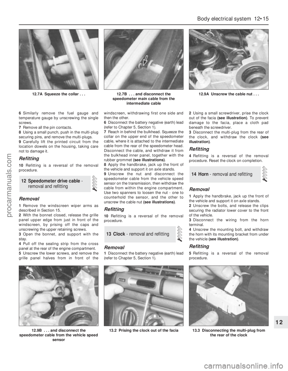
rubber grommet (see illustrations).
8Apply the handbrake, jack up the front of
the vehicle and support it on axle stands.
9Unscrew the nut and disconnect the
speedometer cable from the vehicle speed
sensor on the transmission, then withdraw the
cable from within the engine compartment.
Use two spanners to loosen the nut - one to
counterhold the sensor, and the other to
unscrew the cable nut (see illustrations).Refitting
10Refitting is a reversal of the removal
procedure.
Removal
1Disconnect the battery negative (earth) lead
(refer to Chapter 5, Section 1).2Using a small screwdriver, prise the clock
out of the facia (see illustration). To prevent
damage to the facia, place a cloth pad
beneath the screwdriver.
3Disconnect the multi-plug from the rear of
the clock, and withdraw the clock (see
illustration).
Refitting
4Refitting is a reversal of the removal
procedure. Reset the clock on completion.
Removal
1Apply the handbrake, jack up the front of
the vehicle and support it on axle stands.
2Unscrew the bolts, and release the clips
securing the radiator lower cover to the front
of the vehicle.
3Disconnect the wiring from the horn
terminal.
4Unscrew the mounting bolt, and withdraw
the horn with its mounting bracket from under
the vehicle (see illustration).
Refitting
5Refitting is a reversal of the removal
procedure.
14 Horn - removal and refitting
13 Clock- removal and refitting
12 Speedometer drive cable -
removal and refitting
Body electrical system 12•15
12
12.9B . . . and disconnect the
speedometer cable from the vehicle speed
sensor13.2 Prising the clock out of the facia13.3 Disconnecting the multi-plug from
the rear of the clock
12.7A Squeeze the collar . . .12.7B . . . and disconnect the
speedometer main cable from the
intermediate cable12.9A Unscrew the cable nut . . .
procarmanuals.com
Page 221 of 279
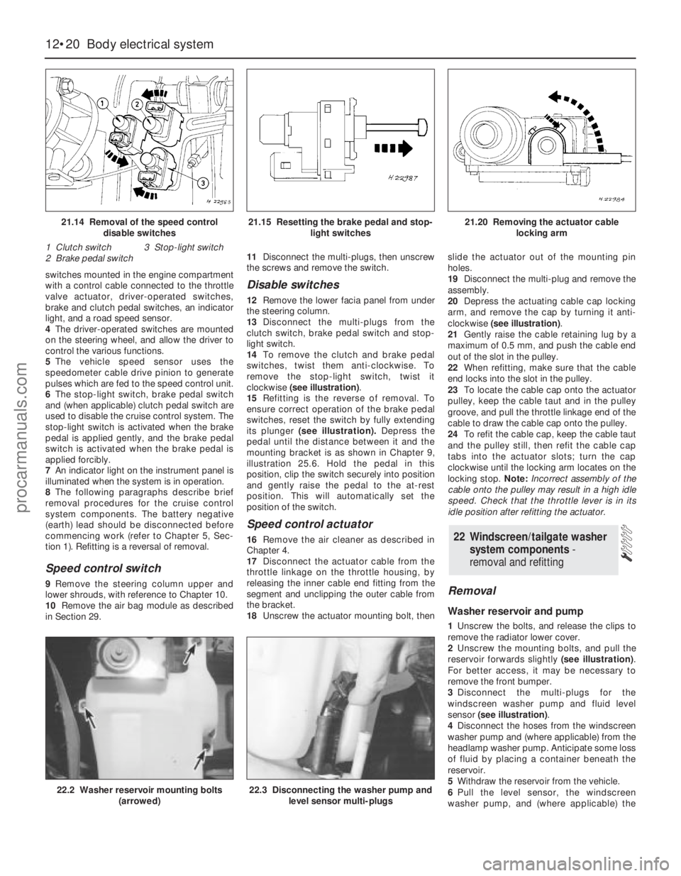
switches mounted in the engine compartment
with a control cable connected to the throttle
valve actuator, driver-operated switches,
brake and clutch pedal switches, an indicator
light, and a road speed sensor.
4The driver-operated switches are mounted
on the steering wheel, and allow the driver to
control the various functions.
5The vehicle speed sensor uses the
speedometer cable drive pinion to generate
pulses which are fed to the speed control unit.
6The stop-light switch, brake pedal switch
and (when applicable) clutch pedal switch are
used to disable the cruise control system. The
stop-light switch is activated when the brake
pedal is applied gently, and the brake pedal
switch is activated when the brake pedal is
applied forcibly.
7An indicator light on the instrument panel is
illuminated when the system is in operation.
8The following paragraphs describe brief
removal procedures for the cruise control
system components. The battery negative
(earth) lead should be disconnected before
commencing work (refer to Chapter 5, Sec-
tion 1). Refitting is a reversal of removal.
Speed control switch
9Remove the steering column upper and
lower shrouds, with reference to Chapter 10.
10Remove the air bag module as described
in Section 29.11Disconnect the multi-plugs, then unscrew
the screws and remove the switch.
Disable switches
12Remove the lower facia panel from under
the steering column.
13Disconnect the multi-plugs from the
clutch switch, brake pedal switch and stop-
light switch.
14To remove the clutch and brake pedal
switches, twist them anti-clockwise. To
remove the stop-light switch, twist it
clockwise (see illustration).
15Refitting is the reverse of removal. To
ensure correct operation of the brake pedal
switches, reset the switch by fully extending
its plunger (see illustration).Depress the
pedal until the distance between it and the
mounting bracket is as shown in Chapter 9,
illustration 25.6. Hold the pedal in this
position, clip the switch securely into position
and gently raise the pedal to the at-rest
position. This will automatically set the
position of the switch.
Speed control actuator
16Remove the air cleaner as described in
Chapter 4.
17Disconnect the actuator cable from the
throttle linkage on the throttle housing, by
releasing the inner cable end fitting from the
segment and unclipping the outer cable from
the bracket.
18Unscrew the actuator mounting bolt, thenslide the actuator out of the mounting pin
holes.
19Disconnect the multi-plug and remove the
assembly.
20Depress the actuating cable cap locking
arm, and remove the cap by turning it anti-
clockwise (see illustration).
21Gently raise the cable retaining lug by a
maximum of 0.5 mm, and push the cable end
out of the slot in the pulley.
22When refitting, make sure that the cable
end locks into the slot in the pulley.
23To locate the cable cap onto the actuator
pulley, keep the cable taut and in the pulley
groove, and pull the throttle linkage end of the
cable to draw the cable cap onto the pulley.
24To refit the cable cap, keep the cable taut
and the pulley still, then refit the cable cap
tabs into the actuator slots; turn the cap
clockwise until the locking arm locates on the
locking stop. Note:Incorrect assembly of the
cable onto the pulley may result in a high idle
speed. Check that the throttle lever is in its
idle position after refitting the actuator.
Removal
Washer reservoir and pump
1Unscrew the bolts, and release the clips to
remove the radiator lower cover.
2Unscrew the mounting bolts, and pull the
reservoir forwards slightly (see illustration).
For better access, it may be necessary to
remove the front bumper.
3Disconnect the multi-plugs for the
windscreen washer pump and fluid level
sensor (see illustration).
4Disconnect the hoses from the windscreen
washer pump and (where applicable) from the
headlamp washer pump. Anticipate some loss
of fluid by placing a container beneath the
reservoir.
5Withdraw the reservoir from the vehicle.
6Pull the level sensor, the windscreen
washer pump, and (where applicable) the
22 Windscreen/tailgate washer
system components -
removal and refitting
12•20 Body electrical system
21.14 Removal of the speed control
disable switches
1 Clutch switch 3 Stop-light switch
2 Brake pedal switch21.15 Resetting the brake pedal and stop-
light switches21.20 Removing the actuator cable
locking arm
22.2 Washer reservoir mounting bolts
(arrowed)22.3 Disconnecting the washer pump and
level sensor multi-plugs
procarmanuals.com