1993 FORD MONDEO fuse box
[x] Cancel search: fuse boxPage 18 of 279
1•4
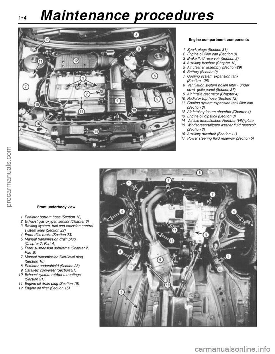
Engine compartment components
1 Spark plugs (Section 31)
2 Engine oil filler cap (Section 3)
3 Brake fluid reservoir (Section 3)
4 Auxiliary fusebox (Chapter 12)
5 Air cleaner assembly (Section 29)
6 Battery (Section 9)
7 Cooling system expansion tank
(Section 28)
8 Ventilation system pollen filter - under
cowl grille panel (Section 27)
9 Air intake resonator (Chapter 4)
10 Radiator top hose (Section 12)
11 Cooling system expansion tank filler cap
(Section 3)
12 Air intake plenum chamber (Chapter 4)
13 Engine oil dipstick (Section 3)
14 Vehicle Identification Number (VIN) plate
15 Windscreen/tailgate washer fluid reservoir
(Section 3)
16 Auxiliary drivebelt (Section 11)
17 Power steering fluid reservoir (Section 5)
Front underbody view
1 Radiator bottom hose (Section 12)
2 Exhaust gas oxygen sensor (Chapter 6)
3 Braking system, fuel and emission control
system lines (Section 22)
4 Front disc brake (Section 23)
5 Manual transmission drain plug
(Chapter 7, Part A)
6 Front suspension subframe (Chapter 2,
Part B)
7 Manual transmission filler/level plug
(Section 16)
8 Radiator undershield (Section 28)
9 Catalytic converter (Section 21)
10 Exhaust system rubber mountings
(Section 21)
11 Engine oil drain plug (Section 15)
12 Engine oil filter (Section 15)
Maintenance procedures
procarmanuals.com
Page 153 of 279
2The function of these components is to
reduce the emission of unburned
hydrocarbons from the crankcase, and to
minimise the formation of oil sludge. By
ensuring that a depression is created in the
crankcase under most operating conditions,
particularly at idle, and by positively inducing
fresh air into the system, the oil vapours and
“blow-by” gases collected in the crankcase
are drawn from the crankcase, through the oil
separator, into the inlet tract, to be burned by
the engine during normal combustion.
Checking
3Checking procedures for the system
components are included in Chapter 1.
Component renewal
Cylinder head-to-air cleaner hose
4See Chapter 1.
Positive Crankcase Ventilation (PCV)
valve
5The valve is plugged into the oil separator.
Depending on the tools available, access to
the valve may be possible once the pulse-air
assembly has been removed (see Section 7).
If this is not feasible, proceed as outlined in
paragraph 6 below.
Oil separator
6Remove the exhaust manifold (see Chap-
ter 2, Part A). The Positive Crankcase
Ventilation (PCV) valve can now be unplugged
and flushed, or renewed, as required, as
described in Chapter 1.
7Unbolt the oil separator from the cylinder
block/crankcase, and withdraw it; remove and
discard the gasket.
8Flush out or renew the oil separator, as
required (see Chapter 1).
9On reassembly, fit a new gasket, and
tighten the fasteners to the torque wrench
settings given in the Specifications Section of
Chapter 2, Part B.
10The remainder of the refitting procedure is
the reverse of removal. Refill the cooling
system (see Chapter 1). Run the engine,
check for exhaust leaks, and check the
coolant level when it is fully warmed-up.
General information
1The exhaust gases of any petrol engine
(however efficient or well-tuned) consist
largely (approximately 99 %) of nitrogen (N
2),
carbon dioxide (CO
2), oxygen (O2), other inert
gases and water vapour (H
2O). The remaining
1 % is made up of the noxious materials
which are currently seen (CO
2apart) as the
major polluters of the environment: carbon
monoxide (CO), unburned hydrocarbons (HC),oxides of nitrogen (NO
x) and some solid
matter, including a small lead content.
2Left to themselves, most of these pollutants
are thought eventually to break down naturally
(CO and NO
x, for example, break down in the
upper atmosphere to release CO
2) having first
caused ground-level environmental problems.
The massive increase world-wide in the use of
motor vehicles, and the current popular
concern for the environment has caused the
introduction in most countries of legislation, in
varying degrees of severity, to combat the
problem.
3The device most commonly used to clean
up vehicle exhausts is the catalytic converter.
It is fitted into the vehicle’s exhaust system,
and uses precious metals (platinum and
palladium or rhodium) as catalysts to speed
up the reaction between the pollutants and
the oxygen in the vehicle’s exhaust gases, CO
and HC being oxidised to form H
2O and CO2and (in the three-way type of catalytic
converter) NO
xbeing reduced to N2. Note:
The catalytic converter is not a filter in the
physical sense; its function is to promote a
chemical reaction, but it is not itself affected
by that reaction.
4The converter consists of an element (or
“substrate”) of ceramic honeycomb, coated
with a combination of precious metals in such
a way as to produce a vast surface area over
which the exhaust gases must flow; the whole
being mounted in a stainless-steel box. A
simple “oxidation” (or “two-way”) catalytic
converter can deal with CO and HC only,
while a “reduction” (or “three-way”) catalytic
converter can deal with CO, HC and NO
x.
Three-way catalytic converters are further
sub-divided into “open-loop” (or
“uncontrolled”) converters which can remove
50 to 70 % of pollutants and “closed-loop”
(also known as “controlled” or “regulated”)
converters which can remove over 90 % of
pollutants.
5The catalytic converter fitted to the Mondeo
models covered in this manual is of the three-
way closed-loop type.
6The catalytic converter is a reliable and
simple device, which needs no maintenance
in itself, but there are some facts of which an
owner should be aware if the converter is to
function properly for its full service life.
(a) DO NOT use leaded petrol in a vehicle
equipped with a catalytic converter - the
lead will coat the precious metals,
reducing their converting efficiency, and
will eventually destroy the converter; it will
also affect the operation of the oxygen
sensor, requiring its renewal if lead-
fouled. Opinions vary as to how much
leaded fuel is necessary to affect the
converter’s performance, and whether it
can recover even if only unleaded petrol is
used afterwards; the best course of action
is, therefore, to assume the worst, and to
ensure that NO leaded petrol is used at
any time.
(b) Always keep the ignition and fuel systemswell-maintained in accordance with the
manufacturer’s schedule (Chapter 1) -
particularly, ensure that the air filter
element, the fuel filter and the spark plugs
are renewed at the correct intervals. If the
intake air/fuel mixture is allowed to
become too rich due to neglect, the
unburned surplus will enter and burn in
the catalytic converter, overheating the
element and eventually destroying the
converter.
(c) If the engine develops a misfire, do not
drive the vehicle at all (or at least as little
as possible) until the fault is cured - the
misfire will allow unburned fuel to enter
the converter, which will result in its
overheating, as noted above. For the
same reason, do not persist if the engine
refuses to start - either trace the problem
and cure it yourself, or have the vehicle
checked immediately by a qualified
mechanic.
(d) Avoid allowing the vehicle to run out of
petrol.
(e) DO NOT push- or tow-start the vehicle
unless no other alternative exists,
especially if the engine and exhaust are at
normal operating temperature. Starting
the engine in this way may soak the
catalytic converter in unburned fuel,
causing it to overheat when the engine
does start - see (b) above.
(f) DO NOT switch off the ignition at high
engine speeds, in particular, do not “blip”
the throttle immediately before switching
off. If the ignition is switched off at
anything above idle speed, unburned fuel
will enter the (very hot) catalytic converter,
with the possible risk of its igniting on the
element and damaging the converter.
(g) Avoid repeated successive cold starts
followed by short journeys. If the
converter is never allowed to reach its
proper working temperature, it will gather
unburned fuel, allowing some to pass into
the atmosphere and the rest to soak in
the element, causing it to overheat when
a long journey is made - see (b) above.
(h) DO NOT use fuel or engine oil additives -
these may contain substances harmful to
the catalytic converter. Similarly, DO NOT
use silicone-based sealants on any part of
the engine or fuel system, and do not use
exhaust sealants on any part of the
exhaust system upstream of the catalytic
converter. Even if the sealant itself does
not contain additives harmful to the
converter, pieces of it may break off and
foul the element, causing local
overheating.
(i) DO NOT continue to use the vehicle if the
engine burns oil to the extent of leaving a
visible trail of blue smoke. Unburned
carbon deposits will clog the converter
passages and reduce its efficiency; in
severe cases, the element will overheat.
(j) Remember that the catalytic converter
operates at very high temperatures -
9 Catalytic converter -
general information, checking
and component renewal
Emissions control systems 6•19
6
procarmanuals.com
Page 200 of 279
Removal
1Disconnect the battery negative (earth) lead
(Chapter 5, Section 1).
2Remove the windscreen wiper arms
(Chapter 12), then remove the cowl from just
in front of the windscreen. The cowl is in two
sections, with retaining screws located along
its front edge. With the cowl removed,
disconnect the speedometer cable by pulling
it from the intermediate inner cable extension.
3Remove the centre console (Section 30),
then unscrew the screws and remove the
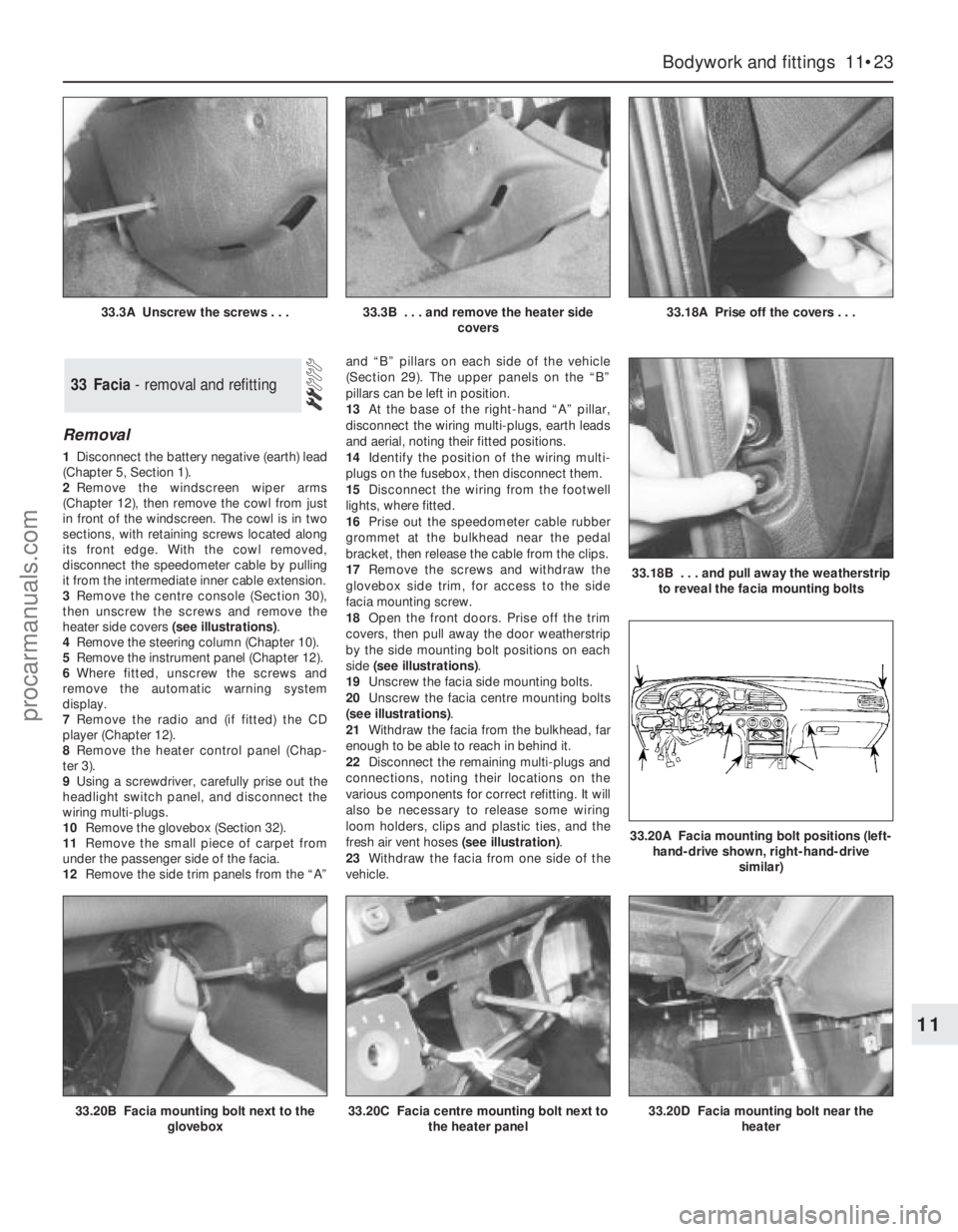
heater side covers (see illustrations).
4Remove the steering column (Chapter 10).
5Remove the instrument panel (Chapter 12).
6Where fitted, unscrew the screws and
remove the automatic warning system
display.
7Remove the radio and (if fitted) the CD
player (Chapter 12).
8Remove the heater control panel (Chap-
ter 3).
9Using a screwdriver, carefully prise out the
headlight switch panel, and disconnect the
wiring multi-plugs.
10Remove the glovebox (Section 32).
11Remove the small piece of carpet from
under the passenger side of the facia.
12Remove the side trim panels from the “A”and “B” pillars on each side of the vehicle
(Section 29). The upper panels on the “B”
pillars can be left in position.
13At the base of the right-hand “A” pillar,
disconnect the wiring multi-plugs, earth leads
and aerial, noting their fitted positions.
14Identify the position of the wiring multi-
plugs on the fusebox, then disconnect them.
15Disconnect the wiring from the footwell
lights, where fitted.
16Prise out the speedometer cable rubber
grommet at the bulkhead near the pedal
bracket, then release the cable from the clips.
17Remove the screws and withdraw the
glovebox side trim, for access to the side
facia mounting screw.
18Open the front doors. Prise off the trim
covers, then pull away the door weatherstrip
by the side mounting bolt positions on each
side (see illustrations).
19Unscrew the facia side mounting bolts.
20Unscrew the facia centre mounting bolts
(see illustrations).
21Withdraw the facia from the bulkhead, far
enough to be able to reach in behind it.
22Disconnect the remaining multi-plugs and
connections, noting their locations on the
various components for correct refitting. It will
also be necessary to release some wiring
loom holders, clips and plastic ties, and the
fresh air vent hoses (see illustration).
23Withdraw the facia from one side of the
vehicle.
33 Facia - removal and refitting
Bodywork and fittings 11•23
11
33.20B Facia mounting bolt next to the
glovebox33.20C Facia centre mounting bolt next to
the heater panel33.20D Facia mounting bolt near the
heater
33.3A Unscrew the screws . . .33.3B . . . and remove the heater side
covers33.18A Prise off the covers . . .
33.18B . . . and pull away the weatherstrip
to reveal the facia mounting bolts
33.20A Facia mounting bolt positions (left-
hand-drive shown, right-hand-drive
similar)
procarmanuals.com
Page 202 of 279
Chapter 12 Body electrical system
Air bag clock spring - removal and refitting . . . . . . . . . . . . . . . . . . . 30
Air bag control module - removal and refitting . . . . . . . . . . . . . . . . . 29
Air bag unit (driver’s side) - removal and refitting . . . . . . . . . . . . . . . 28
Anti-theft alarm system - general information . . . . . . . . . . . . . . . . . . 20
Auxiliary warning system - general information and
component renewal . . . . . . . . . . . . . . . . . . . . . . . . . . . . . . . . . . . . 19
Battery - check, maintenance and charging . . . . . . . . See Chapter 1
Battery - removal and refitting . . . . . . . . . . . . . . . . . . . See Chapter 5
Bulbs (exterior lights) - renewal . . . . . . . . . . . . . . . . . . . . . . . . . . . . . 5
Bulbs (interior lights) - renewal . . . . . . . . . . . . . . . . . . . . . . . . . . . . . 6
Clock - removal and refitting . . . . . . . . . . . . . . . . . . . . . . . . . . . . . . . 13
Compact disc player - removal and refitting . . . . . . . . . . . . . . . . . . . 25
Cruise control system - general information . . . . . . . . . . . . . . . . . . . 21
Electrical fault finding - general information . . . . . . . . . . . . . . . . . . . 2
Electrical system check . . . . . . . . . . . . . . . . . . . . . . . . See Chapter 1
Exterior light units - removal and refitting . . . . . . . . . . . . . . . . . . . . . 7
Fuses, relays and timer module - testing and renewal . . . . . . . . . . . 3
General information . . . . . . . . . . . . . . . . . . . . . . . . . . . . . . . . . . . . . . 1
Headlight beam alignment - checking and adjustment . . . . . . . . . . 8
Headlight levelling motor - removal and refitting . . . . . . . . . . . . . . . 9Horn - removal and refitting . . . . . . . . . . . . . . . . . . . . . . . . . . . . . . . 14
Instrument panel - removal and refitting . . . . . . . . . . . . . . . . . . . . . . 10
Instrument panel components - removal and refitting . . . . . . . . . . . 11
Radio aerial - removal and refitting . . . . . . . . . . . . . . . . . . . . . . . . . . 27
Radio/cassette player - coding, removal and refitting . . . . . . . . . . . 23
Radio/cassette player power amplifier - removal and refitting . . . . . 24
Speakers - removal and refitting . . . . . . . . . . . . . . . . . . . . . . . . . . . . 26
Speedometer drive cable - removal and refitting . . . . . . . . . . . . . . . 12
Stop-light switch - removal and refitting . . . . . . . . . . . See Chapter 9
Switches - removal and refitting . . . . . . . . . . . . . . . . . . . . . . . . . . . . 4
Tailgate wiper motor assembly - removal and refitting . . . . . . . . . . . 17
TCS inhibition switch - removal and refitting . . . . . . . . See Chapter 9
Trip computer module - removal and refitting . . . . . . . . . . . . . . . . . 18
Windscreen/tailgate washer system and wiper blade
check . . . . . . . . . . . . . . . . . . . . . . . . . . . . . . . . . . . . See Chapter 1
Windscreen/tailgate washer system components - removal
and refitting . . . . . . . . . . . . . . . . . . . . . . . . . . . . . . . . . . . . . . . . . . 22
Windscreen wiper motor and linkage - removal and refitting . . . . . . 16
Wiper arms - removal and refitting . . . . . . . . . . . . . . . . . . . . . . . . . . 15
Fuses (auxiliary fusebox in engine compartment)
Note:Fuse ratings and circuits are liable to change from year to year. Consult the handbook supplied with the vehicle, or consult a Ford dealer,
for specific information.
Fuse No Rating Colour Circuit(s) protected
1 80 Black . . . . . . . . . . . . . . . . . . . . . . . . . . Power supply to main fusebox
2 60 Yellow . . . . . . . . . . . . . . . . . . . . . . . . . Radiator electric cooling fans
3 60 Yellow . . . . . . . . . . . . . . . . . . . . . . . . . Diesel engine glow plugs and/or ABS braking system
4 20 Yellow . . . . . . . . . . . . . . . . . . . . . . . . . Ignition system, or ignition and daytime running lights
5 30 Light green . . . . . . . . . . . . . . . . . . . . . . Heated windscreen (left-hand side)
6 30 Light green . . . . . . . . . . . . . . . . . . . . . . Heated windscreen (right-hand side)
7 30 Light green . . . . . . . . . . . . . . . . . . . . . . ABS braking system
8 30 Light green . . . . . . . . . . . . . . . . . . . . . . Air conditioning compressor/heated seats or air conditioning
compressor/daytime running lights
9 20 Light blue . . . . . . . . . . . . . . . . . . . . . . . ECU (petrol), Cold start solenoid (Diesel)
10 20 Light blue . . . . . . . . . . . . . . . . . . . . . . . Ignition switch
11 3 Violet . . . . . . . . . . . . . . . . . . . . . . . . . . ECU memory
12 15 Light blue . . . . . . . . . . . . . . . . . . . . . . . Horn and hazard flasher warning system
13 15 Light blue . . . . . . . . . . . . . . . . . . . . . . . Oxygen sensor
14 15 Light blue . . . . . . . . . . . . . . . . . . . . . . . Fuel pump
15 10 Red . . . . . . . . . . . . . . . . . . . . . . . . . . . Dipped beam headlight (right-hand side)
16 10 Red . . . . . . . . . . . . . . . . . . . . . . . . . . . Dipped beam headlight (left-hand side)
17 10 Red . . . . . . . . . . . . . . . . . . . . . . . . . . . Main beam headlight (right-hand side)
18 10 Red . . . . . . . . . . . . . . . . . . . . . . . . . . . Main beam headlight (left-hand side)
12•1
Easy,suitable for
novice with little
experienceFairly easy,suitable
for beginner with
some experienceFairly difficult,suitable
for competent DIY
mechanicDifficult,suitable for
experienced DIY
mechanicVery difficult,
suitable for expert DIY
or professional
Degrees of difficulty
Specifications Contents
12
procarmanuals.com
Page 203 of 279
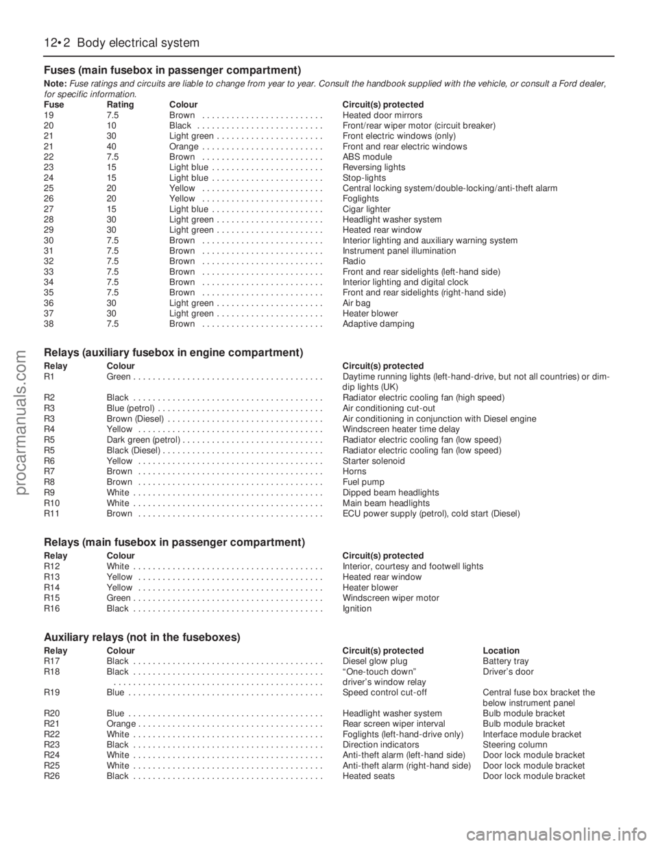
Fuses (main fusebox in passenger compartment)
Note:Fuse ratings and circuits are liable to change from year to year. Consult the handbook supplied with the vehicle, or consult a Ford dealer,
for specific information.
Fuse Rating Colour Circuit(s) protected
19 7.5 Brown . . . . . . . . . . . . . . . . . . . . . . . . . Heated door mirrors
20 10 Black . . . . . . . . . . . . . . . . . . . . . . . . . . Front/rear wiper motor (circuit breaker)
21 30 Light green . . . . . . . . . . . . . . . . . . . . . . Front electric windows (only)
21 40 Orange . . . . . . . . . . . . . . . . . . . . . . . . . Front and rear electric windows
22 7.5 Brown . . . . . . . . . . . . . . . . . . . . . . . . . ABS module
23 15 Light blue . . . . . . . . . . . . . . . . . . . . . . . Reversing lights
24 15 Light blue . . . . . . . . . . . . . . . . . . . . . . . Stop-lights
25 20 Yellow . . . . . . . . . . . . . . . . . . . . . . . . . Central locking system/double-locking/anti-theft alarm
26 20 Yellow . . . . . . . . . . . . . . . . . . . . . . . . . Foglights
27 15 Light blue . . . . . . . . . . . . . . . . . . . . . . . Cigar lighter
28 30 Light green . . . . . . . . . . . . . . . . . . . . . . Headlight washer system
29 30 Light green . . . . . . . . . . . . . . . . . . . . . . Heated rear window
30 7.5 Brown . . . . . . . . . . . . . . . . . . . . . . . . . Interior lighting and auxiliary warning system
31 7.5 Brown . . . . . . . . . . . . . . . . . . . . . . . . . Instrument panel illumination
32 7.5 Brown . . . . . . . . . . . . . . . . . . . . . . . . . Radio
33 7.5 Brown . . . . . . . . . . . . . . . . . . . . . . . . . Front and rear sidelights (left-hand side)
34 7.5 Brown . . . . . . . . . . . . . . . . . . . . . . . . . Interior lighting and digital clock
35 7.5 Brown . . . . . . . . . . . . . . . . . . . . . . . . . Front and rear sidelights (right-hand side)
36 30 Light green . . . . . . . . . . . . . . . . . . . . . . Air bag
37 30 Light green . . . . . . . . . . . . . . . . . . . . . . Heater blower
38 7.5 Brown . . . . . . . . . . . . . . . . . . . . . . . . . Adaptive damping
Relays (auxiliary fusebox in engine compartment)
Relay Colour Circuit(s) protected
R1 Green . . . . . . . . . . . . . . . . . . . . . . . . . . . . . . . . . . . . . . . Daytime running lights (left-hand-drive, but not all countries) or dim-
dip lights (UK)
R2 Black . . . . . . . . . . . . . . . . . . . . . . . . . . . . . . . . . . . . . . . Radiator electric cooling fan (high speed)
R3 Blue (petrol) . . . . . . . . . . . . . . . . . . . . . . . . . . . . . . . . . . Air conditioning cut-out
R3 Brown (Diesel) . . . . . . . . . . . . . . . . . . . . . . . . . . . . . . . . Air conditioning in conjunction with Diesel engine
R4 Yellow . . . . . . . . . . . . . . . . . . . . . . . . . . . . . . . . . . . . . . Windscreen heater time delay
R5 Dark green (petrol) . . . . . . . . . . . . . . . . . . . . . . . . . . . . . Radiator electric cooling fan (low speed)
R5 Black (Diesel) . . . . . . . . . . . . . . . . . . . . . . . . . . . . . . . . . Radiator electric cooling fan (low speed)
R6 Yellow . . . . . . . . . . . . . . . . . . . . . . . . . . . . . . . . . . . . . . Starter solenoid
R7 Brown . . . . . . . . . . . . . . . . . . . . . . . . . . . . . . . . . . . . . . Horns
R8 Brown . . . . . . . . . . . . . . . . . . . . . . . . . . . . . . . . . . . . . . Fuel pump
R9 White . . . . . . . . . . . . . . . . . . . . . . . . . . . . . . . . . . . . . . . Dipped beam headlights
R10 White . . . . . . . . . . . . . . . . . . . . . . . . . . . . . . . . . . . . . . . Main beam headlights
R11 Brown . . . . . . . . . . . . . . . . . . . . . . . . . . . . . . . . . . . . . . ECU power supply (petrol), cold start (Diesel)
Relays (main fusebox in passenger compartment)
Relay Colour Circuit(s) protected
R12 White . . . . . . . . . . . . . . . . . . . . . . . . . . . . . . . . . . . . . . . Interior, courtesy and footwell lights
R13 Yellow . . . . . . . . . . . . . . . . . . . . . . . . . . . . . . . . . . . . . . Heated rear window
R14 Yellow . . . . . . . . . . . . . . . . . . . . . . . . . . . . . . . . . . . . . . Heater blower
R15 Green . . . . . . . . . . . . . . . . . . . . . . . . . . . . . . . . . . . . . . . Windscreen wiper motor
R16 Black . . . . . . . . . . . . . . . . . . . . . . . . . . . . . . . . . . . . . . . Ignition
Auxiliary relays (not in the fuseboxes)
Relay Colour Circuit(s) protected Location
R17 Black . . . . . . . . . . . . . . . . . . . . . . . . . . . . . . . . . . . . . . . Diesel glow plug Battery tray
R18 Black . . . . . . . . . . . . . . . . . . . . . . . . . . . . . . . . . . . . . . . “One-touch down” Driver’s door
. . . . . . . . . . . . . . . . . . . . . . . . . . . . . . . . . . . . . . . . . . . driver’s window relay
R19 Blue . . . . . . . . . . . . . . . . . . . . . . . . . . . . . . . . . . . . . . . . Speed control cut-off Central fuse box bracket the
below instrument panel
R20 Blue . . . . . . . . . . . . . . . . . . . . . . . . . . . . . . . . . . . . . . . . Headlight washer system Bulb module bracket
R21 Orange . . . . . . . . . . . . . . . . . . . . . . . . . . . . . . . . . . . . . . Rear screen wiper interval Bulb module bracket
R22 White . . . . . . . . . . . . . . . . . . . . . . . . . . . . . . . . . . . . . . . Foglights (left-hand-drive only) Interface module bracket
R23 Black . . . . . . . . . . . . . . . . . . . . . . . . . . . . . . . . . . . . . . . Direction indicators Steering column
R24 White . . . . . . . . . . . . . . . . . . . . . . . . . . . . . . . . . . . . . . . Anti-theft alarm (left-hand side) Door lock module bracket
R25 White . . . . . . . . . . . . . . . . . . . . . . . . . . . . . . . . . . . . . . . Anti-theft alarm (right-hand side) Door lock module bracket
R26 Black . . . . . . . . . . . . . . . . . . . . . . . . . . . . . . . . . . . . . . . Heated seats Door lock module bracket
12•2 Body electrical system
procarmanuals.com
Page 206 of 279
remade, prevent the onset of corrosion in the
future by applying a coat of petroleum jelly or
silicone-based grease, or by spraying on (at
regular intervals) a proprietary ignition sealer
such as Holts Damp Start, or a water-
dispersant lubricant such as Holts Wet Start.
Note:It is important to note that the ignition
switch and the appropriate electrical circuit
must always be switched off before any of the
fuses (or relays) are removed and renewed. In
the event of the fuse/relay unit having to be
removed, the battery earth lead must be
disconnected. When reconnecting the battery,
reference should be made to Chapter 5.
1Fuses are designed to break a circuit when
a predetermined current is reached, in order
to protect components and wiring which
could be damaged by excessive current flow.
Any excessive current flow will be due to a
fault in the circuit, usually a short-circuit (see
Section 2). The main fusebox, which also
carries some relays, is located inside the
vehicle below the facia panel on the
passenger’s side, and is accessed by a lever
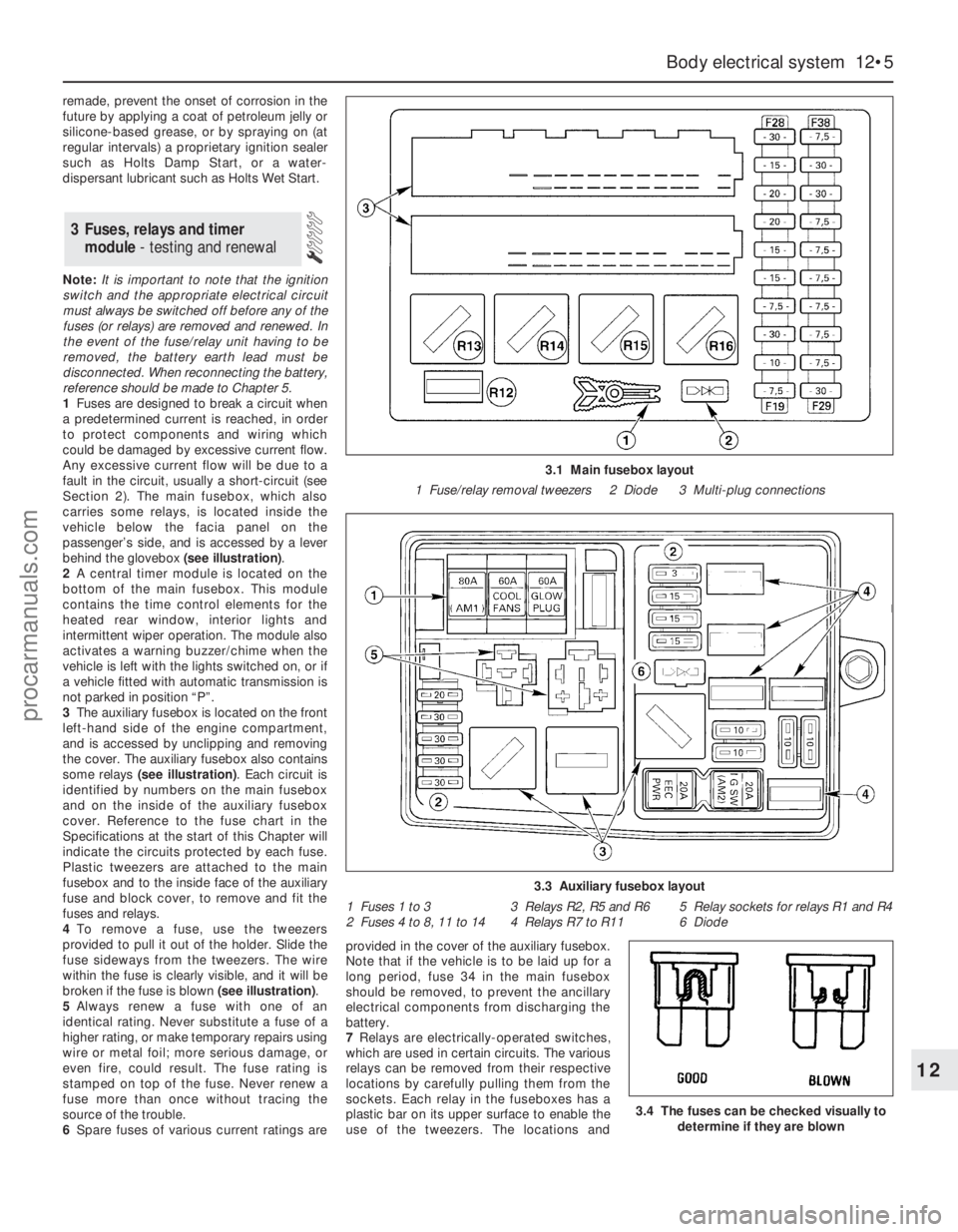
behind the glovebox (see illustration).
2A central timer module is located on the
bottom of the main fusebox. This module
contains the time control elements for the
heated rear window, interior lights and
intermittent wiper operation. The module also
activates a warning buzzer/chime when the
vehicle is left with the lights switched on, or if
a vehicle fitted with automatic transmission is
not parked in position “P”.
3The auxiliary fusebox is located on the front
left-hand side of the engine compartment,
and is accessed by unclipping and removing
the cover. The auxiliary fusebox also contains
some relays (see illustration). Each circuit is
identified by numbers on the main fusebox
and on the inside of the auxiliary fusebox
cover. Reference to the fuse chart in the
Specifications at the start of this Chapter will
indicate the circuits protected by each fuse.
Plastic tweezers are attached to the main
fusebox and to the inside face of the auxiliary
fuse and block cover, to remove and fit the
fuses and relays.
4To remove a fuse, use the tweezers
provided to pull it out of the holder. Slide the
fuse sideways from the tweezers. The wire
within the fuse is clearly visible, and it will be
broken if the fuse is blown (see illustration).
5Always renew a fuse with one of an
identical rating. Never substitute a fuse of a
higher rating, or make temporary repairs using
wire or metal foil; more serious damage, or
even fire, could result. The fuse rating is
stamped on top of the fuse. Never renew a
fuse more than once without tracing the
source of the trouble.
6Spare fuses of various current ratings areprovided in the cover of the auxiliary fusebox.
Note that if the vehicle is to be laid up for a
long period, fuse 34 in the main fusebox
should be removed, to prevent the ancillary
electrical components from discharging the
battery.
7Relays are electrically-operated switches,
which are used in certain circuits. The various
relays can be removed from their respective
locations by carefully pulling them from the
sockets. Each relay in the fuseboxes has a
plastic bar on its upper surface to enable the
use of the tweezers. The locations and
3 Fuses, relays and timer
module- testing and renewal
Body electrical system 12•5
12
3.4 The fuses can be checked visually to
determine if they are blown
3.1 Main fusebox layout
1 Fuse/relay removal tweezers 2 Diode 3 Multi-plug connections
3.3 Auxiliary fusebox layout
1 Fuses 1 to 3 3 Relays R2, R5 and R6 5 Relay sockets for relays R1 and R4
2 Fuses 4 to 8, 11 to 14 4 Relays R7 to R11 6 Diode
procarmanuals.com
Page 207 of 279
functions of the various relays are given in the
Specifications (see illustration).
8If a component controlled by a relay
becomes inoperative and the relay is suspect,
listen to the relay as the circuit is operated. If
the relay is functioning, it should be possible
to hear it click as it is energized. If the relay
proves satisfactory, the fault lies with the
components or wiring of the system. If the
relay is not being energized, then either the
relay is not receiving a switching voltage, or
the relay itself is faulty. (Do not overlook the
relay socket terminals when tracing faults.)
Testing is by the substitution of a known good
unit, but be careful; while some relays are
identical in appearance and in operation,
others look similar, but perform different
functions.9The central timer module located on the
bottom of the main fusebox incorporates its
own self-diagnosis function. Note that
diagnosis cannot take place if the heated rear
window is defective.
10To activate the system, press the heated
rear window button while the ignition is being
switched on, then release the button. Operate
the light switch, washer pump switch and all
of the door switches one after the other, and
check that the buzzer confirms that the input
signals are correct.
11Now move the wiper lever to the
intermittent wipe position, and check the
output signals by operating the same
switches.
12The self-diagnosis function is turned off
by switching the ignition off and on again.
Removal
Ignition switch and lock barrel
1Disconnect the battery negative (earth) lead
(refer to Chapter 5, Section 1).
2Remove the rubber gaiters and locking
rings, then remove the securing screws and
take off the steering column upper and lower
shrouds.
3Insert the ignition key, and turn it to the
accessory position. Using a small screwdriver
or twist drill through the hole in the side of the
lock housing, depress the locking plunger and
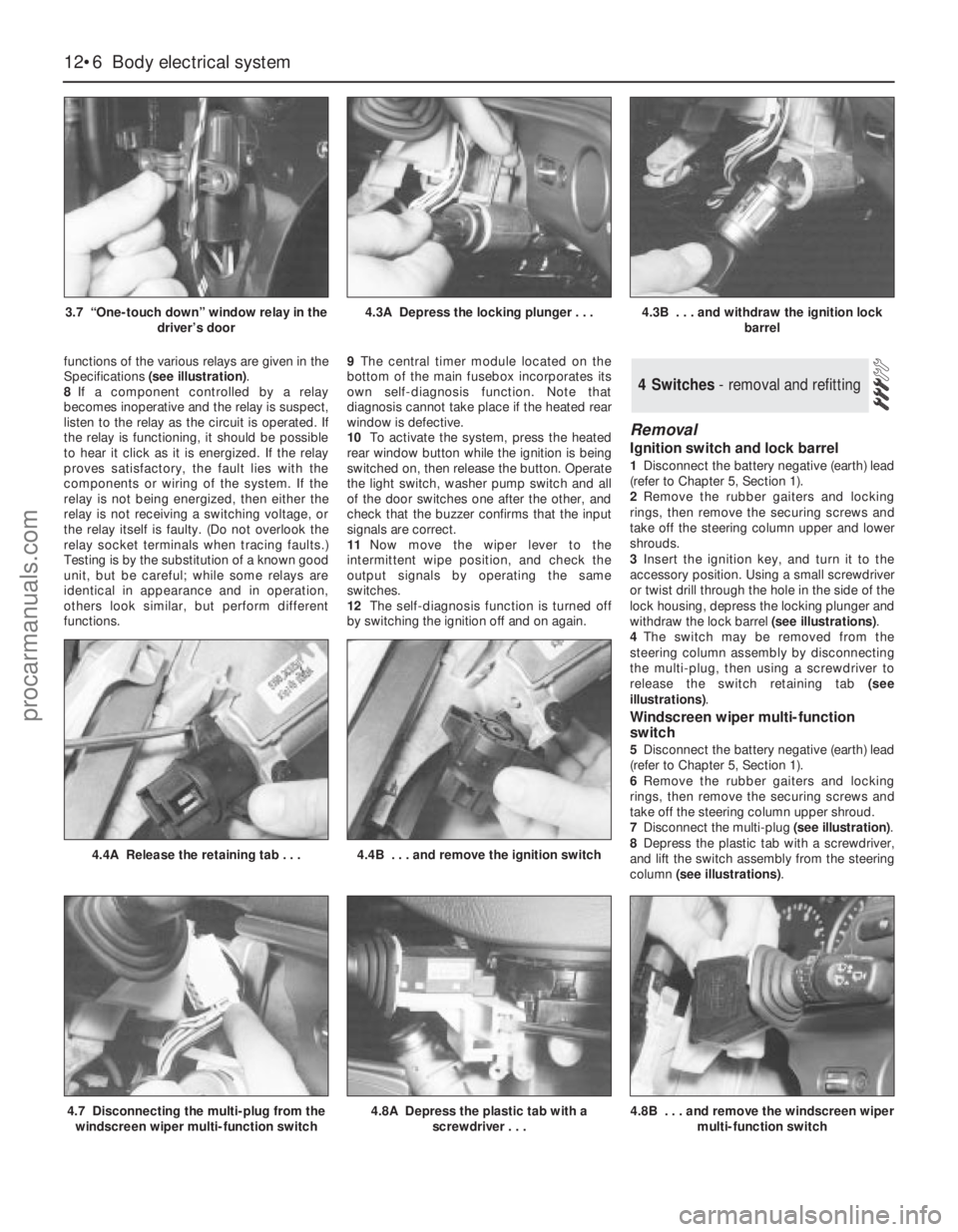
withdraw the lock barrel (see illustrations).
4The switch may be removed from the
steering column assembly by disconnecting
the multi-plug, then using a screwdriver to
release the switch retaining tab (see
illustrations).
Windscreen wiper multi-function
switch
5Disconnect the battery negative (earth) lead
(refer to Chapter 5, Section 1).
6Remove the rubber gaiters and locking
rings, then remove the securing screws and
take off the steering column upper shroud.
7Disconnect the multi-plug (see illustration).
8Depress the plastic tab with a screwdriver,
and lift the switch assembly from the steering
column (see illustrations).
4 Switches - removal and refitting
12•6 Body electrical system
3.7 “One-touch down” window relay in the
driver’s door4.3A Depress the locking plunger . . .4.3B . . . and withdraw the ignition lock
barrel
4.7 Disconnecting the multi-plug from the
windscreen wiper multi-function switch4.8A Depress the plastic tab with a
screwdriver . . .
4.4A Release the retaining tab . . .4.4B . . . and remove the ignition switch
4.8B . . . and remove the windscreen wiper
multi-function switch
procarmanuals.com
Page 277 of 279
REF•18Index
E
Earth fault - 12•4
Economy/Sport mode switch - 12•7
ECU (Electronic Control Unit) - 6•10, 6•11,
6•12
EGR exhaust gas pressure differential
sensor - 6•16
EGR system - 6•15, 6•16
Electric shock - 0•5
Electric windows fault - REF•12
Electrical system - 0•8, 1•11, 1•20
Electrical system fault - REF•12
Electrically-operated windows - 12•7
Electrolyte - 1•8
Electronic control system - 4•9, 6•2
Emblems - 11•17
Emission checks - 0•10
Emissions control systems - 6•1
Engine compartment light - 12•11
Engine electrical systems- 5•1et seq
Engine fault finding - REF•7, REF•8, REF•10
Engine management system - 4•8, 4•9
Engine oil - 1•2, 1•6, 1•16
Engine oil level sensor - 12•18
Engine removal and general engine
overhaul procedures- 2B•1et seq
Environmental considerations - REF•4
Evaporative emissions control (EVAP)
system - 6•14
Evaporator - 3•9
Exhaust gas pressure differential sensor -
6•11, 6•12, 6•13
Exhaust Gas Recirculation (EGR) system -
6•15, 6•16
Exhaust manifold - 2A•8
Exhaust system - 0•9, 0•10, 1•18, 4•12,
REF•9
Expansion tank - 3•5, 3•6
FFacia - 11•21, 11•23
Fan(s) - 3•4, 12•11
Fault code read-out - 6•6
Fault finding- REF•6et seq
Fault finding - automatic transmission -
7B•1
Fault finding - electrical system - 12•4
Filling - 11•3
Fire - 0•5
Fluid level checks - 1•6
Flywheel - 2A•24
Foglight - 12•7, 12•9, 12•13
Foglight warning indicator - 12•11
Fuel and exhaust systems- 0•10, 4•1et
seq
Fuel and exhaust system fault finding -
REF•9
Fuel consumption high - REF•9
Fuel cut-off switch - 4•8
Fuel filter - 1•26
Fuel gauge - 4•6
Fuel gauge fault - REF•12
Fuel hoses - 1•15
Fuel injection system - 4•8, 4•9
Fuel injectors - 4•10
Fuel lines - 1•19, 4•2
Fuel odour - REF•9Fuel pressure check - 4•5
Fuel pressure regulator - 4•11
Fuel pump - 4•5, 4•6
Fuel rail - 4•10
Fuel system - 4•2
Fuel tank - 4•7, 4•8
Fume or gas intoxication - 0•5
Fumes from exhaust system - REF•9
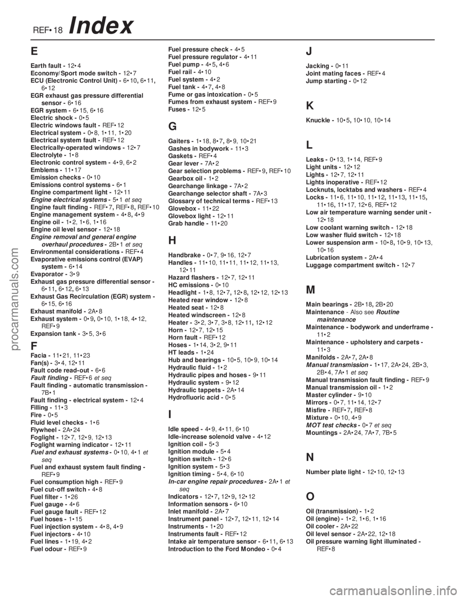
Fuses - 12•5
G
Gaiters - 1•18, 8•7, 8•9, 10•21
Gashes in bodywork - 11•3
Gaskets - REF•4
Gear lever - 7A•2
Gear selection problems - REF•9, REF•10
Gearbox oil - 1•2
Gearchange linkage - 7A•2
Gearchange selector shaft - 7A•3
Glossary of technical terms - REF•13
Glovebox - 11•22
Glovebox light - 12•11
Grab handle - 11•20
H
Handbrake - 0•7, 9•16, 12•7
Handles - 11•10, 11•11, 11•12, 11•13,
12•11
Hazard flashers - 12•7, 12•11
HC emissions - 0•10
Headlight - 1•8, 12•7, 12•8, 12•12, 12•13
Heated rear window - 12•8
Heated seat - 12•8
Heated windscreen - 12•8
Heater - 3•2, 3•7, 3•8, 12•11, 12•12
Horn - 12•7, 12•15
Horn fault - REF•12
Hoses - 1•14, 3•2, 9•11
HT leads - 1•24
Hub and bearings - 10•5, 10•9, 10•14
Hydraulic fluid - 1•2
Hydraulic pipes and hoses - 9•11
Hydraulic system - 9•12
Hydraulic tappets - 2A•14
Hydrofluoric acid - 0•5
I
Idle speed - 4•9, 4•11, 6•10
Idle-increase solenoid valve - 4•12
Ignition coil - 5•3
Ignition module - 5•4
Ignition switch - 12•6
Ignition system - 5•3
Ignition timing - 5•4, 6•10
In-car engine repair procedures- 2A•1et
seq
Indicators - 12•7, 12•9, 12•12
Information sensors - 6•10
Inlet manifold - 2A•7
Instrument panel - 12•7, 12•11, 12•14
Instruments - 1•20
Instruments fault - REF•12
Intake air temperature sensor - 6•11, 6•13
Introduction to the Ford Mondeo - 0•4
J
Jacking - 0•11
Joint mating faces - REF•4
Jump starting - 0•12
K
Knuckle - 10•5, 10•10, 10•14
L
Leaks - 0•13, 1•14, REF•9
Light units - 12•12
Lights - 12•7, 12•11
Lights inoperative - REF•12
Locknuts, locktabs and washers - REF•4
Locks - 11•6, 11•10, 11•12, 11•13, 11•15,
11•16, 11•17, 12•6, REF•12
Low air temperature warning sender unit -
12•18
Low coolant warning switch - 12•18
Low washer fluid switch - 12•18
Lower suspension arm - 10•8, 10•9, 10•13,
10•16
Lubrication system - 2A•4
Luggage compartment switch - 12•7
M
Main bearings - 2B•18, 2B•20
Maintenance- Also see Routine
maintenance
Maintenance - bodywork and underframe -
11•2
Maintenance - upholstery and carpets -
11•3
Manifolds - 2A•7, 2A•8
Manual transmission- 1•17, 2A•24, 2B•3,
2B•4, 7A•1et seq
Manual transmission fault finding - REF•9
Manual transmission oil - 1•2
Master cylinder - 9•10
Mirrors - 0•7, 11•14, 12•7
Misfire - REF•7, REF•8
Mixture - 0•10, 4•9
MOT test checks- 0•7et seq
Mountings - 2A•24, 7A•7, 7B•5
N
Number plate light - 12•10, 12•13
O
Oil (transmission) - 1•2
Oil (engine) - 1•2, 1•6, 1•16
Oil cooler - 2A•22
Oil level sensor - 2A•22, 12•18
Oil pressure warning light illuminated -
REF•8
procarmanuals.com