1993 FORD MONDEO door lock
[x] Cancel search: door lockPage 4 of 279
0•4Introduction
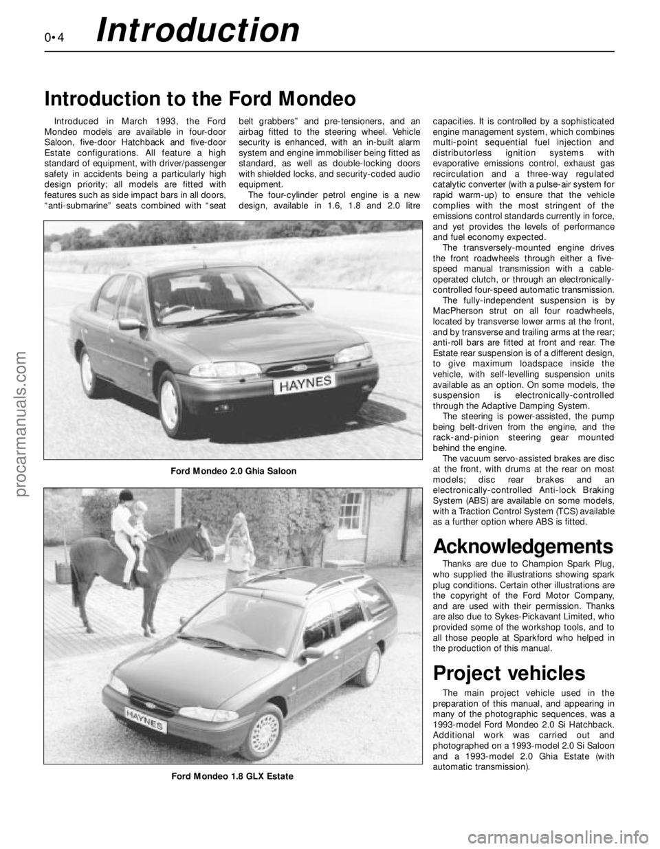
Introduced in March 1993, the Ford
Mondeo models are available in four-door
Saloon, five-door Hatchback and five-door
Estate configurations. All feature a high
standard of equipment, with driver/passenger
safety in accidents being a particularly high
design priority; all models are fitted with
features such as side impact bars in all doors,
“anti-submarine” seats combined with “seatbelt grabbers” and pre-tensioners, and an
airbag fitted to the steering wheel. Vehicle
security is enhanced, with an in-built alarm
system and engine immobiliser being fitted as
standard, as well as double-locking doors
with shielded locks, and security-coded audio
equipment.
The four-cylinder petrol engine is a new
design, available in 1.6, 1.8 and 2.0 litrecapacities. It is controlled by a sophisticated
engine management system, which combines
multi-point sequential fuel injection and
distributorless ignition systems with
evaporative emissions control, exhaust gas
recirculation and a three-way regulated
catalytic converter (with a pulse-air system for
rapid warm-up) to ensure that the vehicle
complies with the most stringent of the
emissions control standards currently in force,
and yet provides the levels of performance
and fuel economy expected.
The transversely-mounted engine drives
the front roadwheels through either a five-
speed manual transmission with a cable-
operated clutch, or through an electronically-
controlled four-speed automatic transmission.
The fully-independent suspension is by
MacPherson strut on all four roadwheels,
located by transverse lower arms at the front,
and by transverse and trailing arms at the rear;
anti-roll bars are fitted at front and rear. The
Estate rear suspension is of a different design,
to give maximum loadspace inside the
vehicle, with self-levelling suspension units
available as an option. On some models, the
suspension is electronically-controlled
through the Adaptive Damping System.
The steering is power-assisted, the pump
being belt-driven from the engine, and the
rack-and-pinion steering gear mounted
behind the engine.
The vacuum servo-assisted brakes are disc
at the front, with drums at the rear on most
models; disc rear brakes and an
electronically-controlled Anti-lock Braking
System (ABS) are available on some models,
with a Traction Control System (TCS) available
as a further option where ABS is fitted.
Acknowledgements
Thanks are due to Champion Spark Plug,
who supplied the illustrations showing spark
plug conditions. Certain other illustrations are
the copyright of the Ford Motor Company,
and are used with their permission. Thanks
are also due to Sykes-Pickavant Limited, who
provided some of the workshop tools, and to
all those people at Sparkford who helped in
the production of this manual.
Project vehicles
The main project vehicle used in the
preparation of this manual, and appearing in
many of the photographic sequences, was a
1993-model Ford Mondeo 2.0 Si Hatchback.
Additional work was carried out and
photographed on a 1993-model 2.0 Si Saloon
and a 1993-model 2.0 Ghia Estate (with
automatic transmission).
Introduction to the Ford Mondeo
Ford Mondeo 2.0 Ghia Saloon
Ford Mondeo 1.8 GLX Estate
procarmanuals.com
Page 8 of 279
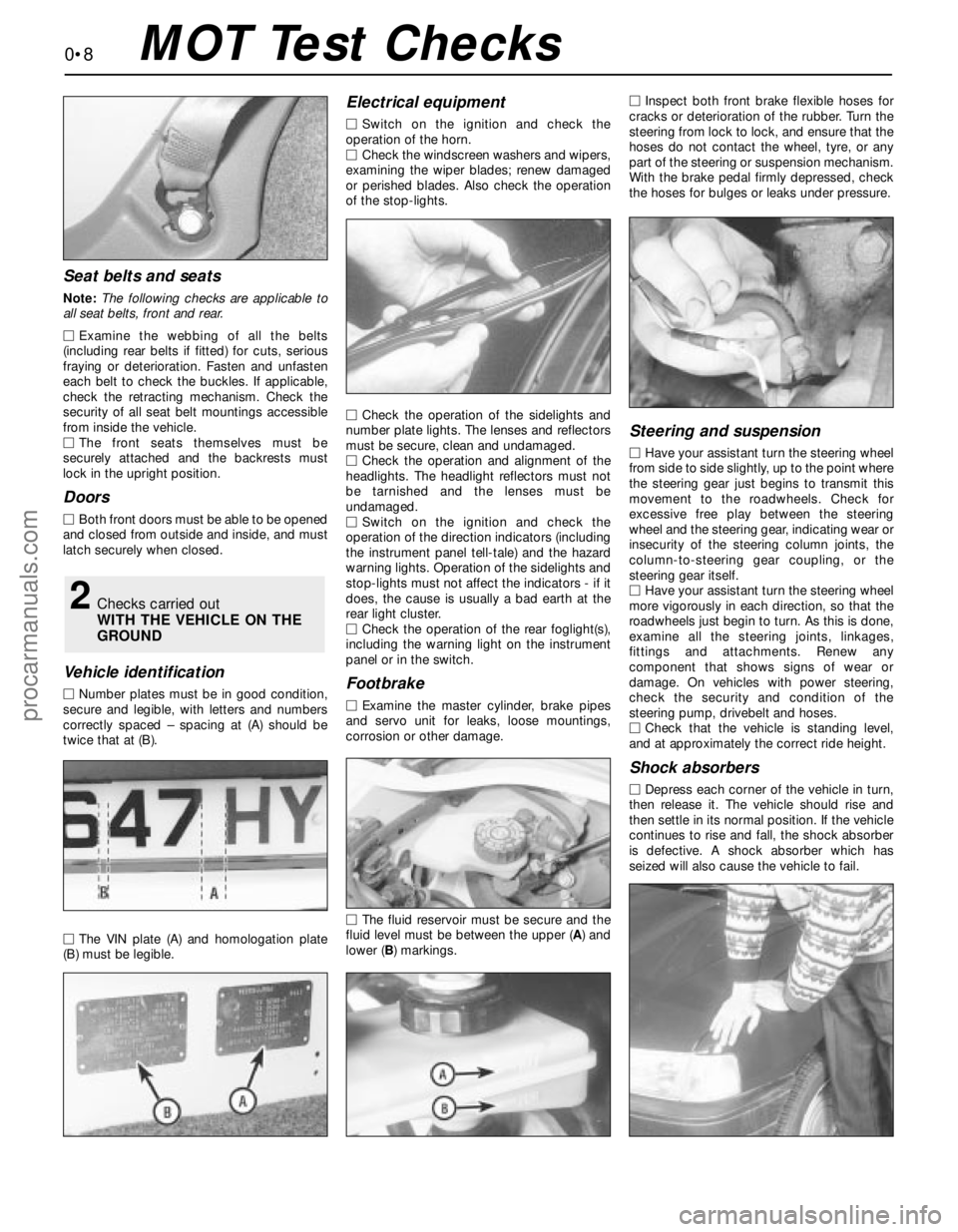
Seat belts and seats
Note: The following checks are applicable to
all seat belts, front and rear.
MExamine the webbing of all the belts
(including rear belts if fitted) for cuts, serious
fraying or deterioration. Fasten and unfasten
each belt to check the buckles. If applicable,
check the retracting mechanism. Check the
security of all seat belt mountings accessible
from inside the vehicle.
MThe front seats themselves must be
securely attached and the backrests must
lock in the upright position.
Doors
MBoth front doors must be able to be opened
and closed from outside and inside, and must
latch securely when closed.
Vehicle identification
MNumber plates must be in good condition,
secure and legible, with letters and numbers
correctly spaced – spacing at (A) should be
twice that at (B).
MThe VIN plate (A) and homologation plate
(B) must be legible.
Electrical equipment
MSwitch on the ignition and check the
operation of the horn.
MCheck the windscreen washers and wipers,
examining the wiper blades; renew damaged
or perished blades. Also check the operation
of the stop-lights.
MCheck the operation of the sidelights and
number plate lights. The lenses and reflectors
must be secure, clean and undamaged.
MCheck the operation and alignment of the
headlights. The headlight reflectors must not
be tarnished and the lenses must be
undamaged.
MSwitch on the ignition and check the
operation of the direction indicators (including
the instrument panel tell-tale) and the hazard
warning lights. Operation of the sidelights and
stop-lights must not affect the indicators - if it
does, the cause is usually a bad earth at the
rear light cluster.
MCheck the operation of the rear foglight(s),
including the warning light on the instrument
panel or in the switch.
Footbrake
MExamine the master cylinder, brake pipes
and servo unit for leaks, loose mountings,
corrosion or other damage.
MThe fluid reservoir must be secure and the
fluid level must be between the upper (A) and
lower (B) markings.MInspect both front brake flexible hoses for
cracks or deterioration of the rubber. Turn the
steering from lock to lock, and ensure that the
hoses do not contact the wheel, tyre, or any
part of the steering or suspension mechanism.
With the brake pedal firmly depressed, check
the hoses for bulges or leaks under pressure.
Steering and suspension
MHave your assistant turn the steering wheel
from side to side slightly, up to the point where
the steering gear just begins to transmit this
movement to the roadwheels. Check for
excessive free play between the steering
wheel and the steering gear, indicating wear or
insecurity of the steering column joints, the
column-to-steering gear coupling, or the
steering gear itself.
MHave your assistant turn the steering wheel
more vigorously in each direction, so that the
roadwheels just begin to turn. As this is done,
examine all the steering joints, linkages,
fittings and attachments. Renew any
component that shows signs of wear or
damage. On vehicles with power steering,
check the security and condition of the
steering pump, drivebelt and hoses.
MCheck that the vehicle is standing level,
and at approximately the correct ride height.
Shock absorbers
MDepress each corner of the vehicle in turn,
then release it. The vehicle should rise and
then settle in its normal position. If the vehicle
continues to rise and fall, the shock absorber
is defective. A shock absorber which has
seized will also cause the vehicle to fail.
2Checks carried out
WITH THE VEHICLE ON THE
GROUND
0•8MOT Test Checks
procarmanuals.com
Page 30 of 279
comb” or compressed air to clean the
condenser.
Warning: Wear eye protection
when using compressed air!
(d) Check that the drain tube from the front
of the evaporator is clear - note that it is
normal to have clear fluid (water) dripping
from this while the system is in operation,
to the extent that quite a large puddle can
be left under the vehicle when it is parked.
2It’s a good idea to operate the system forabout 30 minutes at least once a month,
particularly during the winter. Long term
non-use can cause hardening, and
subsequent failure, of the seals.
3Because of the complexity of the air
conditioning system and the special
equipment necessary to service it, in-depth
fault diagnosis and repairs are not included in
this manual. For more complete information
on the air conditioning system, refer to the
Haynes Automotive Heating and Air
Conditioning Manual.
4The most common cause of poor cooling is
simply a low system refrigerant charge. If a
noticeable drop in cool air output occurs, the
following quick check will help you determine
if the refrigerant level is low.
5Warm the engine up to normal operating
temperature.
6Place the air conditioning temperature
selector at the coldest setting, and put the
blower at the highest setting. Open the doors
- to make sure the air conditioning system
doesn’t cycle off as soon as it cools the
passenger compartment.
7With the compressor engaged - the clutch
will make an audible click, and the centre of
the clutch will rotate - feel the inlet and outlet
pipes at the compressor. One side should be
cold, and one hot. If there’s no perceptible
difference between the two pipes, there’s
something wrong with the compressor or the
system. It might be a low charge - it might be
something else. Take the vehicle to a dealer
service department or an automotive air
conditioning specialist.1Make sure that you have all the necessary
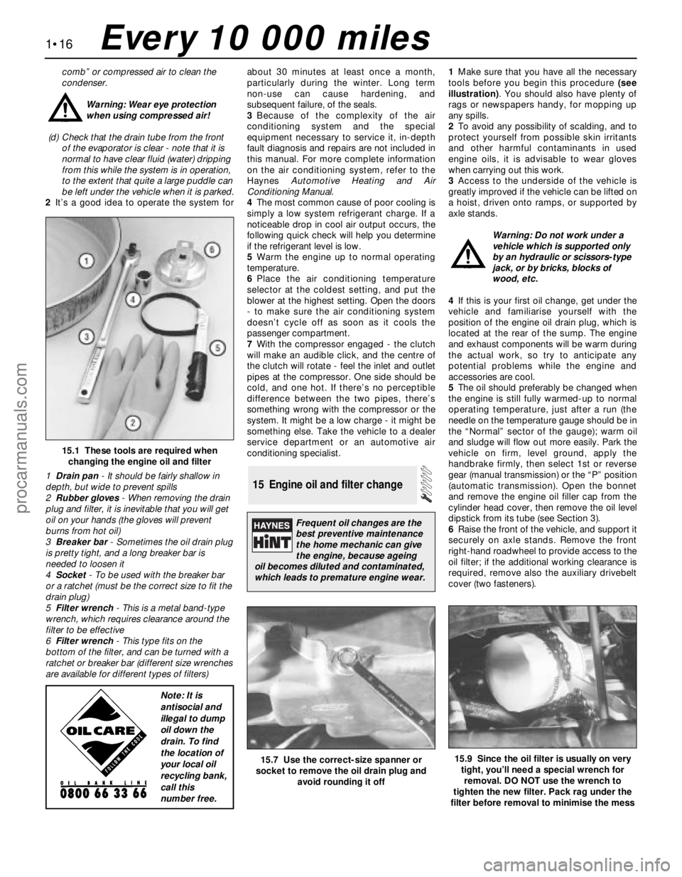
tools before you begin this procedure (see
illustration). You should also have plenty of
rags or newspapers handy, for mopping up
any spills.
2To avoid any possibility of scalding, and to
protect yourself from possible skin irritants
and other harmful contaminants in used
engine oils, it is advisable to wear gloves
when carrying out this work.
3Access to the underside of the vehicle is
greatly improved if the vehicle can be lifted on
a hoist, driven onto ramps, or supported by
axle stands.
Warning: Do not work under a
vehicle which is supported only
by an hydraulic or scissors-type
jack, or by bricks, blocks of
wood, etc.
4If this is your first oil change, get under the
vehicle and familiarise yourself with the
position of the engine oil drain plug, which is
located at the rear of the sump. The engine
and exhaust components will be warm during
the actual work, so try to anticipate any
potential problems while the engine and
accessories are cool.
5The oil should preferably be changed when
the engine is still fully warmed-up to normal
operating temperature, just after a run (the
needle on the temperature gauge should be in
the “Normal” sector of the gauge); warm oil
and sludge will flow out more easily. Park the
vehicle on firm, level ground, apply the
handbrake firmly, then select 1st or reverse
gear (manual transmission) or the “P” position
(automatic transmission). Open the bonnet
and remove the engine oil filler cap from the
cylinder head cover, then remove the oil level
dipstick from its tube (see Section 3).
6Raise the front of the vehicle, and support it
securely on axle stands. Remove the front
right-hand roadwheel to provide access to the
oil filter; if the additional working clearance is
required, remove also the auxiliary drivebelt
cover (two fasteners).
15 Engine oil and filter change
1•16
15.1 These tools are required when
changing the engine oil and filter
1Drain pan- It should be fairly shallow in
depth, but wide to prevent spills
2Rubber gloves- When removing the drain
plug and filter, it is inevitable that you will get
oil on your hands (the gloves will prevent
burns from hot oil)
3Breaker bar- Sometimes the oil drain plug
is pretty tight, and a long breaker bar is
needed to loosen it
4Socket- To be used with the breaker bar
or a ratchet (must be the correct size to fit the
drain plug)
5Filter wrench- This is a metal band-type
wrench, which requires clearance around the
filter to be effective
6Filter wrench- This type fits on the
bottom of the filter, and can be turned with a
ratchet or breaker bar (different size wrenches
are available for different types of filters)
15.7 Use the correct-size spanner or
socket to remove the oil drain plug and
avoid rounding it off15.9 Since the oil filter is usually on very
tight, you’ll need a special wrench for
removal. DO NOT use the wrench to
tighten the new filter. Pack rag under the
filter before removal to minimise the mess
Every 10 000 miles
Frequent oil changes are the
best preventive maintenance
the home mechanic can give
the engine, because ageing
oil becomes diluted and contaminated,
which leads to premature engine wear.
Note: It is
antisocial and
illegal to dump
oil down the
drain. To find
the location of
your local oil
recycling bank,
call this
number free.
procarmanuals.com
Page 34 of 279
brake shoes is not less than the
recommendation given in the Specifications.
14If it is difficult to determine the exact
thickness of the brake shoe linings, or if you
are at all concerned about the condition of the
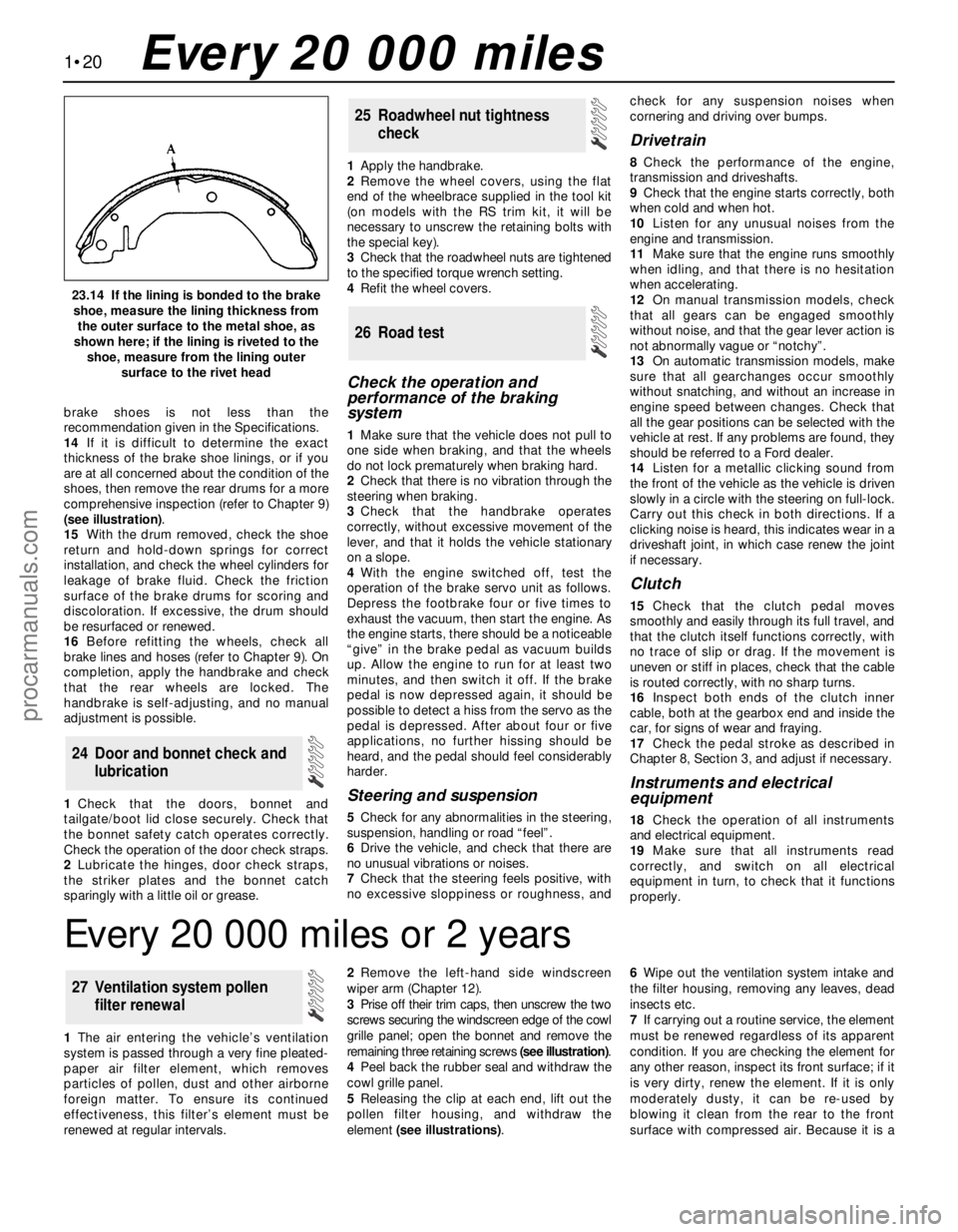
shoes, then remove the rear drums for a more
comprehensive inspection (refer to Chapter 9)
(see illustration).
15With the drum removed, check the shoe
return and hold-down springs for correct
installation, and check the wheel cylinders for
leakage of brake fluid. Check the friction
surface of the brake drums for scoring and
discoloration. If excessive, the drum should
be resurfaced or renewed.
16Before refitting the wheels, check all
brake lines and hoses (refer to Chapter 9). On
completion, apply the handbrake and check
that the rear wheels are locked. The
handbrake is self-adjusting, and no manual
adjustment is possible.
1Check that the doors, bonnet and
tailgate/boot lid close securely. Check that
the bonnet safety catch operates correctly.
Check the operation of the door check straps.
2Lubricate the hinges, door check straps,
the striker plates and the bonnet catch
sparingly with a little oil or grease.1Apply the handbrake.
2Remove the wheel covers, using the flat
end of the wheelbrace supplied in the tool kit
(on models with the RS trim kit, it will be
necessary to unscrew the retaining bolts with
the special key).
3Check that the roadwheel nuts are tightened
to the specified torque wrench setting.
4Refit the wheel covers.
Check the operation and
performance of the braking
system
1Make sure that the vehicle does not pull to
one side when braking, and that the wheels
do not lock prematurely when braking hard.
2Check that there is no vibration through the
steering when braking.
3Check that the handbrake operates
correctly, without excessive movement of the
lever, and that it holds the vehicle stationary
on a slope.
4With the engine switched off, test the
operation of the brake servo unit as follows.
Depress the footbrake four or five times to
exhaust the vacuum, then start the engine. As
the engine starts, there should be a noticeable
“give” in the brake pedal as vacuum builds
up. Allow the engine to run for at least two
minutes, and then switch it off. If the brake
pedal is now depressed again, it should be
possible to detect a hiss from the servo as the
pedal is depressed. After about four or five
applications, no further hissing should be
heard, and the pedal should feel considerably
harder.
Steering and suspension
5Check for any abnormalities in the steering,
suspension, handling or road “feel”.
6Drive the vehicle, and check that there are
no unusual vibrations or noises.
7Check that the steering feels positive, with
no excessive sloppiness or roughness, andcheck for any suspension noises when
cornering and driving over bumps.
Drivetrain
8Check the performance of the engine,
transmission and driveshafts.
9Check that the engine starts correctly, both
when cold and when hot.
10Listen for any unusual noises from the
engine and transmission.
11Make sure that the engine runs smoothly
when idling, and that there is no hesitation
when accelerating.
12On manual transmission models, check
that all gears can be engaged smoothly
without noise, and that the gear lever action is
not abnormally vague or “notchy”.
13On automatic transmission models, make
sure that all gearchanges occur smoothly
without snatching, and without an increase in
engine speed between changes. Check that
all the gear positions can be selected with the
vehicle at rest. If any problems are found, they
should be referred to a Ford dealer.
14Listen for a metallic clicking sound from
the front of the vehicle as the vehicle is driven
slowly in a circle with the steering on full-lock.
Carry out this check in both directions. If a
clicking noise is heard, this indicates wear in a
driveshaft joint, in which case renew the joint
if necessary.
Clutch
15Check that the clutch pedal moves
smoothly and easily through its full travel, and
that the clutch itself functions correctly, with
no trace of slip or drag. If the movement is
uneven or stiff in places, check that the cable
is routed correctly, with no sharp turns.
16Inspect both ends of the clutch inner
cable, both at the gearbox end and inside the
car, for signs of wear and fraying.
17Check the pedal stroke as described in
Chapter 8, Section 3, and adjust if necessary.
Instruments and electrical
equipment
18Check the operation of all instruments
and electrical equipment.
19Make sure that all instruments read
correctly, and switch on all electrical
equipment in turn, to check that it functions
properly.
26 Road test
25 Roadwheel nut tightness
check
24 Door and bonnet check and
lubrication
1•20
23.14 If the lining is bonded to the brake
shoe, measure the lining thickness from
the outer surface to the metal shoe, as
shown here; if the lining is riveted to the
shoe, measure from the lining outer
surface to the rivet head
Every 20 000 miles
Every 20 000 miles or 2 years
1The air entering the vehicle’s ventilation
system is passed through a very fine pleated-
paper air filter element, which removes
particles of pollen, dust and other airborne
foreign matter. To ensure its continued
effectiveness, this filter’s element must be
renewed at regular intervals.2Remove the left-hand side windscreen
wiper arm (Chapter 12).
3Prise off their trim caps, then unscrew the two
screws securing the windscreen edge of the cowl
grille panel; open the bonnet and remove the
remaining three retaining screws (see illustration).
4Peel back the rubber seal and withdraw the
cowl grille panel.
5Releasing the clip at each end, lift out the
pollen filter housing, and withdraw the
element (see illustrations).6Wipe out the ventilation system intake and
the filter housing, removing any leaves, dead
insects etc.
7If carrying out a routine service, the element
must be renewed regardless of its apparent
condition. If you are checking the element for
any other reason, inspect its front surface; if it
is very dirty, renew the element. If it is only
moderately dusty, it can be re-used by
blowing it clean from the rear to the front
surface with compressed air. Because it is a
27 Ventilation system pollen
filter renewal
procarmanuals.com
Page 90 of 279
Torque wrench settingsNm lbf ft
Radiator mounting bracket-to-subframe bolts . . . . . . . . . . . . . . . . . . . . 23 17
Fluid cooler pipe unions - automatic transmission . . . . . . . . . . . . . . . . . 23 17
Thermostat housing-to-cylinder head bolts . . . . . . . . . . . . . . . . . . . . . . 20 15
Water outlet-to-thermostat housing bolts . . . . . . . . . . . . . . . . . . . . . . . 8 to 11 6 to 8
Coolant temperature sensor . . . . . . . . . . . . . . . . . . . . . . . . . . . . . . . . . . 23 17
Coolant temperature gauge sender . . . . . . . . . . . . . . . . . . . . . . . . . . . . 8 6
Water pump bolts . . . . . . . . . . . . . . . . . . . . . . . . . . . . . . . . . . . . . . . . . . 18 13
Water pump pulley bolts . . . . . . . . . . . . . . . . . . . . . . . . . . . . . . . . . . . . . See Chapter 2A
Air conditioning compressor mounting bolts . . . . . . . . . . . . . . . . . . . . . 25 18
3•2 Cooling, heating and air conditioning systems
Engine cooling system
All vehicles covered by this manual employ
a pressurised engine cooling system with
thermostatically-controlled coolant circu-
lation. A water pump mounted on the drivebelt
end of the cylinder block/crankcase pumps
coolant through the engine. The coolant flows
around each cylinder and toward the
transmission end of the engine. Cast-in
coolant passages direct coolant around the
inlet and exhaust ports, near the spark
plug areas and close to the exhaust valve
guides.
A wax pellet type thermostat is located in a
housing at the transmission end of the engine.
During warm-up, the closed thermostat
prevents coolant from circulating through the
radiator. Instead, it returns through the
coolant metal pipe running across the front of
the engine to the radiator bottom hose and
the water pump. The supply to the heater is
made from the rear of the thermostat housing.
As the engine nears normal operating
temperature, the thermostat opens and allows
hot coolant to travel through the radiator,
where it is cooled before returning to the
engine.
The cooling system is sealed by a pressure-
type filler cap in the expansion tank. The
pressure in the system raises the boiling point
of the coolant, and increases the cooling
efficiency of the radiator. When the engine is
at normal operating temperature, the coolant
expands, and the surplus is displaced into the
expansion tank. When the system cools, the
surplus coolant is automatically drawn back
from the tank into the radiator.
Warning: DO NOT attempt to
remove the expansion tank filler
cap, or to disturb any part of the
cooling system, while it or the
engine is hot, as there is a very great risk
of scalding. If the expansion tank filler cap
must be removed before the engine and
radiator have fully cooled down (even
though this is not recommended) the
pressure in the cooling system must first
be released. Cover the cap with a thick
layer of cloth, to avoid scalding, and slowly
unscrew the filler cap until a hissing sound
can be heard. When the hissing hasstopped, showing that pressure is
released, slowly unscrew the filler cap
further until it can be removed; if more
hissing sounds are heard, wait until they
have stopped before unscrewing the cap
completely. At all times, keep well away
from the filler opening.
Warning: Do not allow antifreeze
to come in contact with your
skin, or with the painted surfaces
of the vehicle. Rinse off spills
immediately with plenty of water. Never
leave antifreeze lying around in an open
container, or in a puddle in the driveway or
on the garage floor. Children and pets are
attracted by its sweet smell, but antifreeze
is fatal if ingested.
Warning: If the engine is hot, the
electric cooling fan may start
rotating even if the engine is not
running, so be careful to keep
hands, hair and loose clothing well clear
when working in the engine compartment.
Heating system
The heating system consists of a blower fan
and heater matrix (radiator) located in the
heater unit, with hoses connecting the heater
matrix to the engine cooling system. Hot
engine coolant is circulated through the
heater matrix. When the heater temperature
control on the facia is operated, a flap door
opens to expose the heater box to the
passenger compartment. When the blower
control is operated, the blower fan forces air
through the unit according to the setting
selected.
Air conditioning system
See Section 11.
Warning: Do not allow antifreeze to come in
contact with your skin, or with the painted
surfaces of the vehicle. Rinse off spills
immediately with plenty of water. Antifreeze is
highly toxic if ingested. Never leave antifreeze
lying around in an open container, or in
puddles on the floor; children and pets are
attracted by its sweet smell, and may drink it.
Check with local authorities about disposing
of used antifreeze - many have collection
centres which will see that antifreeze is
disposed of safely.The cooling system should be filled with a
water/ethylene glycol-based antifreeze
solution, of a strength which will prevent
freezing down to at least -25°C, or lower if the
local climate requires it. Antifreeze also
provides protection against corrosion, and
increases the coolant boiling point.
The cooling system should be maintained
according to the schedule described in
Chapter 1. If antifreeze is used that is not to
Ford’s specification, old or contaminated
coolant mixtures are likely to cause damage,
and encourage the formation of corrosion and
scale in the system. Use distilled water with
the antifreeze, if available - if not, be sure to
use only soft water. Clean rainwater is
suitable.
Before adding antifreeze, check all hoses
and hose connections, because antifreeze
tends to leak through very small openings.
Engines don’t normally consume coolant, so if
the level goes down, find the cause and
correct it.
The exact mixture of antifreeze-to-water
which you should use depends on the
relative weather conditions. The mixture
should contain at least 40% antifreeze, but
not more than 70%. Consult the mixture
ratio chart on the antifreeze container
before adding coolant. Hydrometers are
available at most automotive accessory
shops to test the coolant. Use antifreeze
which meets the vehicle manufacturer’s
specifications.
Note:Refer to the warnings given in Section 1
of this Chapter before starting work.
1If the checks described in Chapter 1 reveal
a faulty hose, it must be renewed as follows
(see illustration).
2First drain the cooling system (see Chap-
ter 1); if the antifreeze is not due for renewal,
the drained coolant may be re-used, if it is
collected in a clean container.
3To disconnect any hose, use a pair of pliers
to release the spring clamps (or a screwdriver
to slacken screw-type clamps), then move
them along the hose clear of the union.
Carefully work the hose off its stubs. The
hoses can be removed with relative ease
when new - on an older car, they may have
stuck.
3 Cooling system hoses -
disconnection and renewal
2 Antifreeze - general information
1 General information
procarmanuals.com
Page 178 of 279
Chapter 11 Bodywork and fittings
Body side-trim mouldings and adhesive emblems - removal
and refitting . . . . . . . . . . . . . . . . . . . . . . . . . . . . . . . . . . . . . . . . . . 25
Bonnet - removal, refitting and adjustment . . . . . . . . . . . . . . . . . . . . 8
Bonnet lock - removal, refitting and adjustment . . . . . . . . . . . . . . . . 10
Bonnet release cable and lever - removal and refitting . . . . . . . . . . . 9
Boot lid - removal and refitting . . . . . . . . . . . . . . . . . . . . . . . . . . . . . 18
Boot lid lock components - removal and refitting . . . . . . . . . . . . . . . 19
Bumpers - removal and refitting . . . . . . . . . . . . . . . . . . . . . . . . . . . . 6
Central locking system components - testing, removal and refitting . 23
Centre console - removal and refitting . . . . . . . . . . . . . . . . . . . . . . . 30
Door - removal and refitting . . . . . . . . . . . . . . . . . . . . . . . . . . . . . . . 15
Door handle and lock components - removal and refitting . . . . . . . . 14
Door inner trim panel - removal and refitting . . . . . . . . . . . . . . . . . . 11
Door window glass - removal and refitting . . . . . . . . . . . . . . . . . . . . 12
Door window regulator - removal and refitting . . . . . . . . . . . . . . . . . 13
Exterior mirror and glass - removal and refitting . . . . . . . . . . . . . . . . 16
Facia - removal and refitting . . . . . . . . . . . . . . . . . . . . . . . . . . . . . . . 33
General information . . . . . . . . . . . . . . . . . . . . . . . . . . . . . . . . . . . . . . 1Glovebox - removal and refitting . . . . . . . . . . . . . . . . . . . . . . . . . . . . 32
Interior mirror - removal and refitting . . . . . . . . . . . . . . . . . . . . . . . . 17
Interior trim panels - removal and refitting . . . . . . . . . . . . . . . . . . . . 29
Maintenance - bodywork and underframe . . . . . . . . . . . . . . . . . . . . 2
Maintenance - upholstery and carpets . . . . . . . . . . . . . . . . . . . . . . . 3
Major body damage - repair . . . . . . . . . . . . . . . . . . . . . . . . . . . . . . . 5
Minor body damage - repair . . . . . . . . . . . . . . . . . . . . . . . . . . . . . . . 4
Overhead console - removal and refitting . . . . . . . . . . . . . . . . . . . . . 31
Radiator grille - removal and refitting . . . . . . . . . . . . . . . . . . . . . . . . 7
Seat belts - removal and refitting . . . . . . . . . . . . . . . . . . . . . . . . . . . 28
Seats - removal and refitting . . . . . . . . . . . . . . . . . . . . . . . . . . . . . . . 27
Sunroof - general information and adjustment . . . . . . . . . . . . . . . . . 26
Tailgate - removal and refitting . . . . . . . . . . . . . . . . . . . . . . . . . . . . . 20
Tailgate lock components - removal and refitting . . . . . . . . . . . . . . . 22
Tailgate support strut - removal and refitting . . . . . . . . . . . . . . . . . . 21
Wheel arch liner - removal and refitting . . . . . . . . . . . . . . . . . . . . . . 34
Windscreen and fixed windows - removal and refitting . . . . . . . . . . 24
Torque wrench settingsNm lbf ft
Bonnet and tailgate hinges . . . . . . . . . . . . . . . . . . . . . . . . . . . . . . . . . . . 24 18
Boot lid . . . . . . . . . . . . . . . . . . . . . . . . . . . . . . . . . . . . . . . . . . . . . . . . . . 10 7
Front seat mounting bolts . . . . . . . . . . . . . . . . . . . . . . . . . . . . . . . . . . . . 38 28
Seat belt mounting nuts and bolts . . . . . . . . . . . . . . . . . . . . . . . . . . . . . 38 28
Bumper mounting nuts . . . . . . . . . . . . . . . . . . . . . . . . . . . . . . . . . . . . . . 10 7
11•1
Easy,suitable for
novice with little
experienceFairly easy,suitable
for beginner with
some experienceFairly difficult,suitable
for competent DIY
mechanicDifficult,suitable for
experienced DIY
mechanicVery difficult,
suitable for expert DIY
or professional
Degrees of difficulty
Specifications Contents
11
The bodyshell and underframe on all
models is of all-steel welded construction,
incorporating progressive crumple zones at
the front and rear, and a rigid centre safety
cell. The bulkhead behind the engine
compartment incorporates crash grooves
which determine its energy-absorption
characteristics, and special beams to prevent
the intrusion of the front wheels into the
passenger compartment during a serious
accident. All passenger doors incorporate
side impact bars.
All sheet metal surfaces which are prone tocorrosion are galvanized. The painting
process includes a base colour which closely
matches the final topcoat, so that any stone
damage is not noticeable.
Hatchback, Saloon and Estate versions are
available. The front section of the vehicle up to
the “B” pillar is identical on all models.
Automatic seat belts are fitted to all models,
and the front seat belt stalks are mounted on
automatic tensioners (also known as
“grabbers”) (see illustration). In the event of a
serious front impact, a spring mass sensor
releases a coil spring which pulls the stalk
buckle downwards and tensions the seat belt.
It is not possible to reset the tensioner once
fired, and it must therefore be renewed.
In the UK, central locking is standard on all
1 General information
1.4 Automatic seat belt tensioner
1 Coil spring 3 Spring mass sensor
2 Lever system
procarmanuals.com
Page 179 of 279
models (see illustration). In other countries, it
is available on certain models only. Where
double-locking is fitted, the lock mechanism
is disconnected (when the system is in use)
from the interior door handles, making it
impossible to open any of the doors or the
tailgate/bootlid from inside the vehicle. This
means that, even if a thief should break a side
window, he will not be able to open the door
using the interior handle. Models with the
double-locking system are fitted with a
control module located beneath the facia on
the right-hand side. In the event of a serious
accident, a crash sensor unlocks all doors if
they were previously locked.
Many of the procedures in this Chapter
require the battery to be disconnected. Refer
to Chapter 5, Section 1 first.
The general condition of a vehicle’s
bodywork is the one thing that significantly
affects its value. Maintenance is easy, but
needs to be regular. Neglect, particularly after
minor damage, can lead quickly to further
deterioration and costly repair bills. It is
important also to keep watch on those parts
of the vehicle not immediately visible, for
instance the underside, inside all the wheel
arches, and the lower part of the engine
compartment.
The basic maintenance routine for the
bodywork is washing - preferably with a lot of
water, from a hose. This will remove all the
loose solids which may have stuck to the
vehicle. It is important to flush these off in
such a way as to prevent grit from scratching
the finish. The wheel arches and underframe
need washing in the same way, to remove any
accumulated mud, which will retain moisture
and tend to encourage rust. Paradoxically
enough, the best time to clean the underframe
and wheel arches is in wet weather, when the
mud is thoroughly wet and soft. In very wet
weather, the underframe is usually cleaned of
large accumulations automatically, and this is
a good time for inspection.
Periodically, except on vehicles with a wax-
based underbody protective coating, it is a
good idea to have the whole of the
underframe of the vehicle steam-cleaned,
engine compartment included, so that a
thorough inspection can be carried out to see
what minor repairs and renovations are
necessary. Steam-cleaning is available at
many garages, and is necessary for the
removal of the accumulation of oily grime,
which sometimes is allowed to become thick
in certain areas. If steam-cleaning facilities are
not available, there are some excellent grease
solvents available which can be brush-
applied; the dirt can then be simply hosed off.
Note that these methods should not be used
on vehicles with wax-based underbodyprotective coating, or the coating will be
removed. Such vehicles should be inspected
annually, preferably just prior to Winter, when
the underbody should be washed down, and
any damage to the wax coating repaired.
Ideally, a completely fresh coat should be
applied. It would also be worth considering
the use of such wax-based protection for
injection into door panels, sills, box sections,
etc, as an additional safeguard against rust
damage, where such protection is not
provided by the vehicle manufacturer.
After washing paintwork, wipe off with a
chamois leather to give an unspotted clear
finish. A coat of clear protective wax polish
will give added protection against chemical
pollutants in the air. If the paintwork sheenhas dulled or oxidised, use a cleaner/polisher
combination to restore the brilliance of the
shine. This requires a little effort, but such
dulling is usually caused because regular
washing has been neglected. Care needs to
be taken with metallic paintwork, as special
non-abrasive cleaner/polisher is required to
avoid damage to the finish. Always check that
the door and ventilator opening drain holes
and pipes are completely clear, so that water
can be drained out. Brightwork should be
treated in the same way as paintwork.
Windscreens and windows can be kept clear
of the smeary film which often appears, by the
use of proprietary glass cleaner. Never use
any form of wax or other body or chromium
polish on glass.
2 Maintenance -
bodywork and underframe
11•2 Bodywork and fittings
1.5 Central locking component locations
1 Indicator light
2 Buzzer
3 Central locking module4 Infra-red receiver
5 Lock motor
6 Set/reset switch7 Ajar switch
8 Infra-red transmitter
procarmanuals.com
Page 181 of 279
Mix up a little filler on a clean piece of card
or board - measure the hardener carefully
(follow the maker’s instructions on the pack),
otherwise the filler will set too rapidly or too
slowly. Using the applicator, apply the filler
paste to the prepared area; draw the
applicator across the surface of the filler to
achieve the correct contour and to level the
surface. As soon as a contour that
approximates to the correct one is achieved,
stop working the paste - if you carry on too
long, the paste will become sticky and begin
to “pick-up” on the applicator. Continue to
add thin layers of filler paste at 20-minute
intervals, until the level of the filler is just
proud of the surrounding bodywork.
Once the filler has hardened, the excess
can be removed using a metal plane or file.
From then on, progressively-finer grades of
abrasive paper should be used, starting with a
40-grade production paper, and finishing with
a 400-grade wet-and-dry paper. Always wrap
the abrasive paper around a flat rubber, cork,
or wooden block - otherwise the surface of
the filler will not be completely flat. During the
smoothing of the filler surface, the wet-and-
dry paper should be periodically rinsed in
water. This will ensure that a very smooth
finish is imparted to the filler at the final stage.
At this stage, the “dent” should be
surrounded by a ring of bare metal, which in
turn should be encircled by the finely
“feathered” edge of the good paintwork.
Rinse the repair area with clean water, until all
of the dust produced by the rubbing-down
operation has gone.
Spray the whole area with a light coat of
primer - this will show up any imperfections in
the surface of the filler. Repair these
imperfections with fresh filler paste or
bodystopper, and once more smooth the
surface with abrasive paper. Repeat this
spray-and-repair procedure until you are
satisfied that the surface of the filler, and the
feathered edge of the paintwork, are perfect.
Clean the repair area with clean water, and
allow to dry fully.
The repair area is now ready for final
spraying. Paint spraying must be carried out
in a warm, dry, windless and dust-free
atmosphere. This condition can be created
artificially if you have access to a large indoor
working area, but if you are forced to work in
the open, you will have to pick your day very
carefully. If you are working indoors, dousing
the floor in the work area with water will help
to settle the dust which would otherwise be in
the atmosphere. If the repair area is confined
to one body panel, mask off the surrounding
panels; this will help to minimise the effects ofa slight mis-match in paint colours. Bodywork
fittings (eg chrome strips, door handles etc)
will also need to be masked off. Use genuine
masking tape, and several thicknesses of
newspaper, for the masking operations.
Before commencing to spray, agitate the
aerosol can thoroughly, then spray a test area
(an old tin, or similar) until the technique is
mastered. Cover the repair area with a thick
coat of primer; the thickness should be built
up using several thin layers of paint, rather
than one thick one. Using 400-grade wet-and-
dry paper, rub down the surface of the primer
until it is really smooth. While doing this, the
work area should be thoroughly doused with
water, and the wet-and-dry paper periodically
rinsed in water. Allow to dry before spraying
on more paint.
Spray on the top coat, again building up the
thickness by using several thin layers of paint.
Start spraying at one edge of the repair area,
and then, using a side-to-side motion, work
until the whole repair area and about 2 inches
of the surrounding original paintwork is
covered. Remove all masking material 10 to
15 minutes after spraying on the final coat of
paint.
Allow the new paint at least two weeks to
harden, then, using a paintwork renovator, or
a very fine cutting paste, blend the edges of
the paint into the existing paintwork. Finally,
apply wax polish.
Plastic components
With the use of more and more plastic body
components by the vehicle manufacturers (eg
bumpers. spoilers, and in some cases major
body panels), rectification of more serious
damage to such items has become a matter
of either entrusting repair work to a specialist
in this field, or renewing complete
components. Repair of such damage by the
DIY owner is not really feasible, owing to the
cost of the equipment and materials required
for effecting such repairs. The basic technique
involves making a groove along the line of the
crack in the plastic, using a rotary burr in a
power drill. The damaged part is then welded
back together, using a hot-air gun to heat up
and fuse a plastic filler rod into the groove.
Any excess plastic is then removed, and the
area rubbed down to a smooth finish. It is
important that a filler rod of the correct plastic
is used, as body components can be made of
a variety of different types (eg polycarbonate,
ABS, polypropylene).
Damage of a less serious nature (abrasions,
minor cracks etc) can be repaired by the DIY
owner using a two-part epoxy filler repair
material. Once mixed in equal proportions,
this is used in similar fashion to the bodywork
filler used on metal panels. The filler is usually
cured in twenty to thirty minutes, ready for
sanding and painting.
If the owner is renewing a complete
component himself, or if he has repaired it
with epoxy filler, he will be left with theproblem of finding a suitable paint for finishing
which is compatible with the type of plastic
used. At one time, the use of a universal paint
was not possible, owing to the complex range
of plastics encountered in body component
applications. Standard paints, generally
speaking, will not bond to plastic or rubber
satisfactorily. However, it is now possible to
obtain a plastic body parts finishing kit which
consists of a pre-primer treatment, a primer
and coloured top coat. Full instructions are
normally supplied with a kit, but basically, the
method of use is to first apply the pre-primer
to the component concerned, and allow it to
dry for up to 30 minutes. Then the primer is
applied, and left to dry for about an hour
before finally applying the special-coloured
top coat. The result is a correctly-coloured
component, where the paint will flex with the
plastic or rubber, a property that standard
paint does not normally posses.
Where serious damage has occurred, or
large areas need renewal due to neglect, it
means that complete new panels will need
welding-in; this is best left to professionals. If
the damage is due to impact, it will also be
necessary to check completely the alignment
of the bodyshell; this can only be carried out
accurately by a Ford dealer, using special jigs.
If the body is left misaligned, it is primarily
dangerous, as the car will not handle properly,
and secondly, uneven stresses will be
imposed on the steering, suspension and
possibly transmission, causing abnormal wear
or complete failure, particularly to items such
as the tyres.
Removal
Front bumper
1Apply the handbrake, jack up the front of
the vehicle and support it on axle stands.
2Where applicable, remove the foglights
from the front bumper (Chapter 12).
3Where applicable, disconnect the tubing
from the headlight washer jets.
4Unscrew the screws securing the wheel
arch liners to the front bumper (see
illustration).
5Unscrew the bumper mounting nuts, and
withdraw the bumper forwards from the
vehicle, at the same time disconnecting the
guides from the side pins (see illustrations).
Rear bumper
6Chock the front wheels, jack up the rear of
the vehicle and support it on axle stands.
6 Bumpers - removal and refitting
5 Major body damage - repair
11•4 Bodywork and fittings
If bodystopper is used, it can
be mixed with cellulose
thinners, to form a really thin
paste which is ideal for filling
small holes.
procarmanuals.com