1993 FORD MONDEO key
[x] Cancel search: keyPage 34 of 279
brake shoes is not less than the
recommendation given in the Specifications.
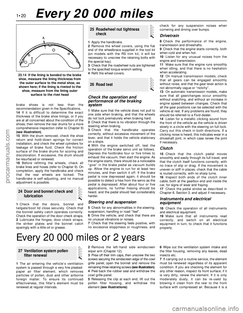
14If it is difficult to determine the exact
thickness of the brake shoe linings, or if you
are at all concerned about the condition of the
shoes, then remove the rear drums for a more
comprehensive inspection (refer to Chapter 9)
(see illustration).
15With the drum removed, check the shoe
return and hold-down springs for correct
installation, and check the wheel cylinders for
leakage of brake fluid. Check the friction
surface of the brake drums for scoring and
discoloration. If excessive, the drum should
be resurfaced or renewed.
16Before refitting the wheels, check all
brake lines and hoses (refer to Chapter 9). On
completion, apply the handbrake and check
that the rear wheels are locked. The
handbrake is self-adjusting, and no manual
adjustment is possible.
1Check that the doors, bonnet and
tailgate/boot lid close securely. Check that
the bonnet safety catch operates correctly.
Check the operation of the door check straps.
2Lubricate the hinges, door check straps,
the striker plates and the bonnet catch
sparingly with a little oil or grease.1Apply the handbrake.
2Remove the wheel covers, using the flat
end of the wheelbrace supplied in the tool kit
(on models with the RS trim kit, it will be
necessary to unscrew the retaining bolts with
the special key).
3Check that the roadwheel nuts are tightened
to the specified torque wrench setting.
4Refit the wheel covers.
Check the operation and
performance of the braking
system
1Make sure that the vehicle does not pull to
one side when braking, and that the wheels
do not lock prematurely when braking hard.
2Check that there is no vibration through the
steering when braking.
3Check that the handbrake operates
correctly, without excessive movement of the
lever, and that it holds the vehicle stationary
on a slope.
4With the engine switched off, test the
operation of the brake servo unit as follows.
Depress the footbrake four or five times to
exhaust the vacuum, then start the engine. As
the engine starts, there should be a noticeable
“give” in the brake pedal as vacuum builds
up. Allow the engine to run for at least two
minutes, and then switch it off. If the brake
pedal is now depressed again, it should be
possible to detect a hiss from the servo as the
pedal is depressed. After about four or five
applications, no further hissing should be
heard, and the pedal should feel considerably
harder.
Steering and suspension
5Check for any abnormalities in the steering,
suspension, handling or road “feel”.
6Drive the vehicle, and check that there are
no unusual vibrations or noises.
7Check that the steering feels positive, with
no excessive sloppiness or roughness, andcheck for any suspension noises when
cornering and driving over bumps.
Drivetrain
8Check the performance of the engine,
transmission and driveshafts.
9Check that the engine starts correctly, both
when cold and when hot.
10Listen for any unusual noises from the
engine and transmission.
11Make sure that the engine runs smoothly
when idling, and that there is no hesitation
when accelerating.
12On manual transmission models, check
that all gears can be engaged smoothly
without noise, and that the gear lever action is
not abnormally vague or “notchy”.
13On automatic transmission models, make
sure that all gearchanges occur smoothly
without snatching, and without an increase in
engine speed between changes. Check that
all the gear positions can be selected with the
vehicle at rest. If any problems are found, they
should be referred to a Ford dealer.
14Listen for a metallic clicking sound from
the front of the vehicle as the vehicle is driven
slowly in a circle with the steering on full-lock.
Carry out this check in both directions. If a
clicking noise is heard, this indicates wear in a
driveshaft joint, in which case renew the joint
if necessary.
Clutch
15Check that the clutch pedal moves
smoothly and easily through its full travel, and
that the clutch itself functions correctly, with
no trace of slip or drag. If the movement is
uneven or stiff in places, check that the cable
is routed correctly, with no sharp turns.
16Inspect both ends of the clutch inner
cable, both at the gearbox end and inside the
car, for signs of wear and fraying.
17Check the pedal stroke as described in
Chapter 8, Section 3, and adjust if necessary.
Instruments and electrical
equipment
18Check the operation of all instruments
and electrical equipment.
19Make sure that all instruments read
correctly, and switch on all electrical
equipment in turn, to check that it functions
properly.
26 Road test
25 Roadwheel nut tightness
check
24 Door and bonnet check and
lubrication
1•20
23.14 If the lining is bonded to the brake
shoe, measure the lining thickness from
the outer surface to the metal shoe, as
shown here; if the lining is riveted to the
shoe, measure from the lining outer
surface to the rivet head
Every 20 000 miles
Every 20 000 miles or 2 years
1The air entering the vehicle’s ventilation
system is passed through a very fine pleated-
paper air filter element, which removes
particles of pollen, dust and other airborne
foreign matter. To ensure its continued
effectiveness, this filter’s element must be
renewed at regular intervals.2Remove the left-hand side windscreen
wiper arm (Chapter 12).
3Prise off their trim caps, then unscrew the two
screws securing the windscreen edge of the cowl
grille panel; open the bonnet and remove the
remaining three retaining screws (see illustration).
4Peel back the rubber seal and withdraw the
cowl grille panel.
5Releasing the clip at each end, lift out the
pollen filter housing, and withdraw the
element (see illustrations).6Wipe out the ventilation system intake and
the filter housing, removing any leaves, dead
insects etc.
7If carrying out a routine service, the element
must be renewed regardless of its apparent
condition. If you are checking the element for
any other reason, inspect its front surface; if it
is very dirty, renew the element. If it is only
moderately dusty, it can be re-used by
blowing it clean from the rear to the front
surface with compressed air. Because it is a
27 Ventilation system pollen
filter renewal
procarmanuals.com
Page 46 of 279
specifications were available from Ford, but a
typical reading would be in excess of 12 bars.
All cylinders should produce very similar
pressures; any difference greater than 10%
indicates the existence of a fault. Note that the
compression should build up quickly in a
healthy engine; low compression on the first
stroke, followed by gradually-increasing
pressure on successive strokes, indicates worn
piston rings. A low compression reading on the
first stroke, which does not build up during
successive strokes, indicates leaking valves or a
blown head gasket (a cracked head could also
be the cause). Deposits on the undersides of the
valve heads can also cause low compression.
8If the pressure in any cylinder is
considerably lower than the others, introduce
a teaspoonful of clean oil into that cylinder
through its spark plug hole, and repeat the
test.
9If the addition of oil temporarily improves
the compression pressure, this indicates that
bore or piston wear is responsible for the
pressure loss. No improvement suggests that
leaking or burnt valves, or a blown head
gasket, may be to blame.
10A low reading from two adjacent cylinders
is almost certainly due to the head gasket
having blown between them; the presence of
coolant in the engine oil will confirm this.
11If one cylinder is about 20 percent lower
than the others and the engine has a slightly
rough idle, a worn camshaft lobe or faulty
hydraulic tappet could be the cause.
12If the compression is unusually high, the
combustion chambers are probably coated
with carbon deposits. If this is the case, the
cylinder head should be removed and
decarbonised.
13On completion of the test, refit the spark
plugs, then reconnect the ignition system and
fuel pump.
General
1Top Dead Centre (TDC) is the highest point
in its travel up-and-down its cylinder bore
that each piston reaches as the crankshaftrotates. While each piston reaches TDC both
at the top of the compression stroke and
again at the top of the exhaust stroke, for the
purpose of timing the engine, TDC refers to
the piston position (usually No 1 piston) at the
top of its compression stroke.
2It is useful for several servicing procedures
to be able to position the engine at TDC.
3No 1 piston and cylinder are at the right-
hand (timing belt) end of the engine (right-
and left-hand are always quoted as seen from
the driver’s seat). Note that the crankshaft
rotates clockwise when viewed from the
right-hand side of the vehicle.
Locating TDC
4Remove all the spark plugs (Chapter 1).
5Disconnect both battery leads - see
Chapter 5, Section 1 - unless the starter
motor is to be used to turn the engine.
6Apply the handbrake and ensure that the
transmission is in neutral, then jack up the
front right-hand side of the vehicle and
support on an axle stand. Remove the
roadwheel.
7Remove the auxiliary drivebelt cover (see
Chapter 1) to expose the crankshaft pulley
and timing marks.
8It is best to rotate the crankshaft using a
spanner applied to the crankshaft pulley bolt;
however, it is possible also to use the starter
motor (switched on either by an assistant
using the ignition key, or by using a remote
starter switch) to bring the engine close to
TDC, then finish with a spanner. If the starter
is used, be sure to disconnect the battery
leads immediately it is no longer required.
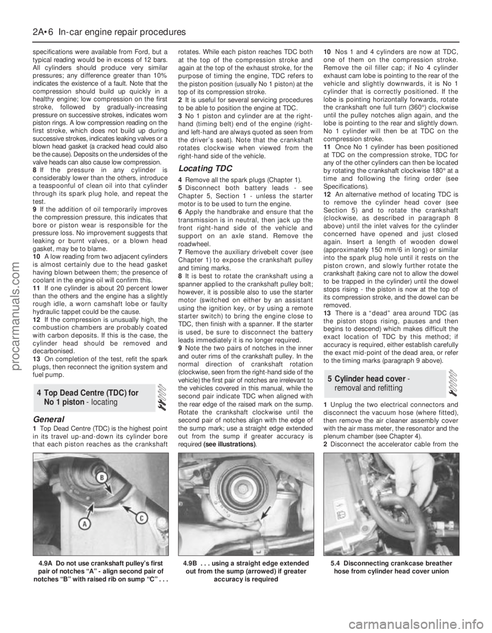
9Note the two pairs of notches in the inner
and outer rims of the crankshaft pulley. In the
normal direction of crankshaft rotation
(clockwise, seen from the right-hand side of the
vehicle) the first pair of notches are irrelevant to
the vehicles covered in this manual, while the
second pair indicate TDC when aligned with
the rear edge of the raised mark on the sump.
Rotate the crankshaft clockwise until the
second pair of notches align with the edge of
the sump mark; use a straight edge extended
out from the sump if greater accuracy is
required (see illustrations).10Nos 1 and 4 cylinders are now at TDC,
one of them on the compression stroke.
Remove the oil filler cap; if No 4 cylinder
exhaust cam lobe is pointing to the rear of the
vehicle and slightly downwards, it is No 1
cylinder that is correctly positioned. If the
lobe is pointing horizontally forwards, rotate
the crankshaft one full turn (360°) clockwise
until the pulley notches align again, and the
lobe is pointing to the rear and slightly down.
No 1 cylinder will then be at TDC on the
compression stroke.
11Once No 1 cylinder has been positioned
at TDC on the compression stroke, TDC for
any of the other cylinders can then be located
by rotating the crankshaft clockwise 180° at a
time and following the firing order (see
Specifications).
12An alternative method of locating TDC is
to remove the cylinder head cover (see
Section 5) and to rotate the crankshaft
(clockwise, as described in paragraph 8
above) until the inlet valves for the cylinder
concerned have opened and just closed
again. Insert a length of wooden dowel
(approximately 150 mm/6 in long) or similar
into the spark plug hole until it rests on the
piston crown, and slowly further rotate the
crankshaft (taking care not to allow the dowel
to be trapped in the cylinder) until the dowel
stops rising - the piston is now at the top of
its compression stroke, and the dowel can be
removed.
13There is a “dead” area around TDC (as
the piston stops rising, pauses and then
begins to descend) which makes difficult the
exact location of TDC by this method; if
accuracy is required, either establish carefully
the exact mid-point of the dead area, or refer
to the timing marks (paragraph 9 above).
1Unplug the two electrical connectors and
disconnect the vacuum hose (where fitted),
then remove the air cleaner assembly cover
with the air mass meter, the resonator and the
plenum chamber (see Chapter 4).
2Disconnect the accelerator cable from the
5 Cylinder head cover-
removal and refitting
4 Top Dead Centre (TDC) for
No 1 piston - locating
2A•6 In-car engine repair procedures
4.9A Do not use crankshaft pulley’s first
pair of notches “A” - align second pair of
notches “B” with raised rib on sump “C” . . .4.9B . . . using a straight edge extended
out from the sump (arrowed) if greater
accuracy is required5.4 Disconnecting crankcase breather
hose from cylinder head cover union
procarmanuals.com
Page 50 of 279
using the method outlined in (2) above.
(2) If the vehicle is fitted with automatic
transmission, see (2) above.
(c) If the engine/transmission has been
removed and separated, use the method
shown in illustration 21.11.
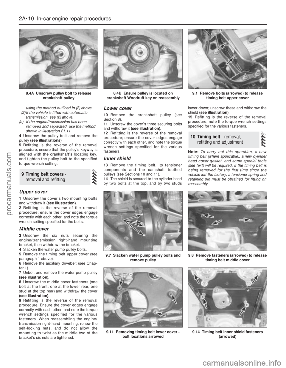
4Unscrew the pulley bolt and remove the
pulley (see illustrations).
5Refitting is the reverse of the removal
procedure; ensure that the pulley’s keyway is
aligned with the crankshaft’s locating key,
and tighten the pulley bolt to the specified
torque wrench setting.
Upper cover
1Unscrew the cover’s two mounting bolts
and withdraw it (see illustration).
2Refitting is the reverse of the removal
procedure; ensure the cover edges engage
correctly with each other, and note the torque
wrench setting specified for the bolts.
Middle cover
3Unscrew the six nuts securing the
engine/transmission right-hand mounting
bracket, then withdraw the bracket.
4Slacken the water pump pulley bolts.
5Remove the timing belt upper cover (see
paragraph 1 above).
6Remove the auxiliary drivebelt (see Chap-
ter 1).
7Unbolt and remove the water pump pulley
(see illustration).
8Unscrew the middle cover fasteners (one
bolt at the front, one at the lower rear, one
stud at the top rear) and withdraw the cover
(see illustration).
9Refitting is the reverse of the removal
procedure. Ensure the cover edges engage
correctly with each other, and note the torque
wrench settings specified for the various
fasteners. When reassembling the engine/
transmission right-hand mounting, renew the
self-locking nuts, and do not allow the
mounting to twist as the middle two of the
bracket’s six nuts are tightened.
Lower cover
10Remove the crankshaft pulley (see
Section 8).
11Unscrew the cover’s three securing bolts
and withdraw it (see illustration).
12Refitting is the reverse of the removal
procedure; ensure the cover edges engage
correctly with each other, and note the torque
wrench settings specified for the various
fasteners.
Inner shield
13Remove the timing belt, its tensioner
components and the camshaft toothed
pulleys (see Sections 10 and 11).
14The shield is secured to the cylinder head
by two bolts at the top, and by two studslower down; unscrew these and withdraw the
shield (see illustration).
15Refitting is the reverse of the removal
procedure; note the torque wrench settings
specified for the various fasteners.
Note:To carry out this operation, a new
timing belt (where applicable), a new cylinder
head cover gasket, and some special tools
(see text) will be required. If the timing belt is
being removed for the first time since the
vehicle left the factory, a tensioner spring and
retaining pin must be obtained for fitting on
reassembly.
10 Timing belt - removal,
refitting and adjustment
9 Timing belt covers-
removal and refitting
2A•10 In-car engine repair procedures
8.4A Unscrew pulley bolt to release
crankshaft pulley8.4B Ensure pulley is located on
crankshaft Woodruff key on reassembly9.1 Remove bolts (arrowed) to release
timing belt upper cover
9.8 Remove fasteners (arrowed) to release
timing belt middle cover9.7 Slacken water pump pulley bolts and
remove pulley
9.11 Removing timing belt lower cover -
bolt locations arrowed9.14 Timing belt inner shield fasteners
(arrowed)
procarmanuals.com
Page 51 of 279
1With the vehicle parked on firm level
ground, open the bonnet and disconnect the
battery negative (earth) lead - see Chapter 5,
Section 1 (see illustration).
2Unbolt the power steering high-pressure
pipe from the cylinder head rear support
plate/engine lifting eye, and from the front
support plate/pump bracket.
3Unscrew the six nuts securing the
engine/transmission right-hand mounting
bracket, then withdraw the bracket.
4Slacken the water pump pulley bolts.5Remove the cylinder head cover (see
Section 5).
6Remove the spark plugs, covering their
holes with clean rag, to prevent dirt or other
foreign bodies from dropping in (see Chap-
ter 1).
7Remove the auxiliary drivebelt (see Chap-
ter 1).
8Rotate the crankshaft clockwise until the
second pair of notches in the pulley rim align
with the edge of the sump mark, so that Nos
1 and 4 cylinders are at TDC (see Section 4).9Unbolt and remove the water pump pulley
and the auxiliary drivebelt idler pulley.
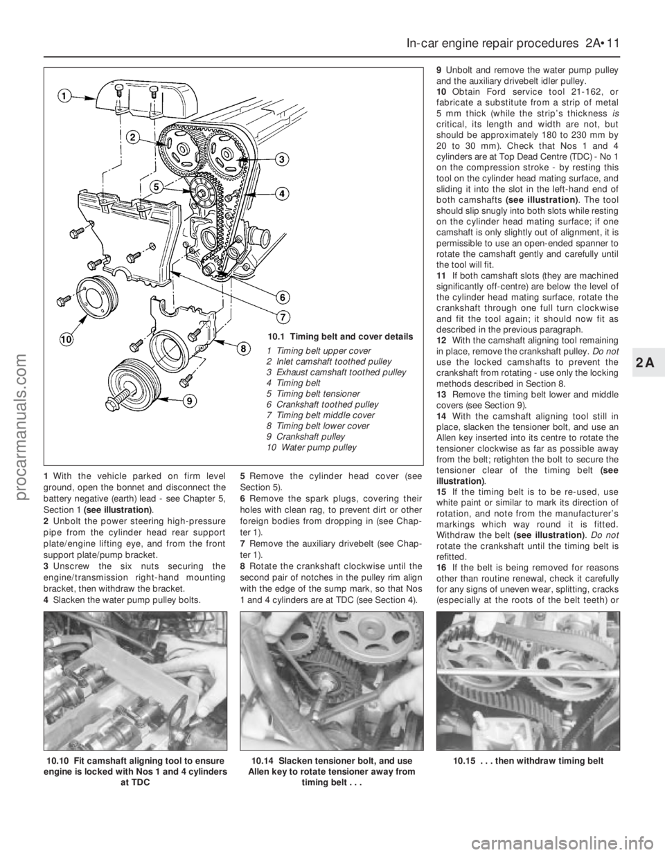
10Obtain Ford service tool 21-162, or
fabricate a substitute from a strip of metal
5 mm thick (while the strip’s thickness is
critical, its length and width are not, but
should be approximately 180 to 230 mm by
20 to 30 mm). Check that Nos 1 and 4
cylinders are at Top Dead Centre (TDC) - No 1
on the compression stroke - by resting this
tool on the cylinder head mating surface, and
sliding it into the slot in the left-hand end of
both camshafts (see illustration). The tool
should slip snugly into both slots while resting
on the cylinder head mating surface; if one
camshaft is only slightly out of alignment, it is
permissible to use an open-ended spanner to
rotate the camshaft gently and carefully until
the tool will fit.
11If both camshaft slots (they are machined
significantly off-centre) are below the level of
the cylinder head mating surface, rotate the
crankshaft through one full turn clockwise
and fit the tool again; it should now fit as
described in the previous paragraph.
12With the camshaft aligning tool remaining
in place, remove the crankshaft pulley. Do not
use the locked camshafts to prevent the
crankshaft from rotating - use only the locking
methods described in Section 8.
13Remove the timing belt lower and middle
covers (see Section 9).
14With the camshaft aligning tool still in
place, slacken the tensioner bolt, and use an
Allen key inserted into its centre to rotate the
tensioner clockwise as far as possible away
from the belt; retighten the bolt to secure the
tensioner clear of the timing belt (see
illustration).
15If the timing belt is to be re-used, use
white paint or similar to mark its direction of
rotation, and note from the manufacturer’s
markings which way round it is fitted.
Withdraw the belt (see illustration). Do not
rotate the crankshaft until the timing belt is
refitted.
16If the belt is being removed for reasons
other than routine renewal, check it carefully
for any signs of uneven wear, splitting, cracks
(especially at the roots of the belt teeth) or
In-car engine repair procedures 2A•11
2A
10.10 Fit camshaft aligning tool to ensure
engine is locked with Nos 1 and 4 cylinders
at TDC10.14 Slacken tensioner bolt, and use
Allen key to rotate tensioner away from
timing belt . . .10.15 . . . then withdraw timing belt
10.1 Timing belt and cover details
1 Timing belt upper cover
2 Inlet camshaft toothed pulley
3 Exhaust camshaft toothed pulley
4 Timing belt
5 Timing belt tensioner
6 Crankshaft toothed pulley
7 Timing belt middle cover
8 Timing belt lower cover
9 Crankshaft pulley
10 Water pump pulley
procarmanuals.com
Page 52 of 279
contamination with oil or coolant. Renew the
belt if there is the slightest doubt about its
condition. As a safety measure, the belt must
be renewed as a matter of course at the
intervals given in Chapter 1; if its history is
unknown, the belt should be renewed
irrespective of its apparent condition
whenever the engine is overhauled. Similarly,
check the tensioner spring (where fitted),
renewing it if there is any doubt about its
condition. Check also the toothed pulleys for
signs of wear or damage, and ensure that the
tensioner and guide pulleys rotate smoothly
on their bearings; renew any worn or
damaged components. If signs of oil or
coolant contamination are found, trace the
source of the leak and rectify it, then wash
down the engine timing belt area and related
components, to remove all traces of oil or
coolant.
17On reassembly, temporarily refit the
crankshaft pulley, to check that the pulley
notches and sump rib are aligned as
described in paragraph 8 above, then ensure
that both camshafts are aligned at TDC by
the special tool (paragraph 10). If the engine
is being reassembled after major dismantling,
both camshaft toothed pulleys should be free
to rotate on their respective camshafts; if the
timing belt alone is being renewed, both
pulleys should still be securely fastened.
18A holding tool will be required to prevent
the camshaft toothed pulleys from rotating
while their bolts are slackened and
retightened; either obtain Ford service tool15-030A, or fabricate a substitute as follows.
Find two lengths of steel strip, one
approximately 600 mm long and the other
about 200 mm, and three bolts with nuts and
washers; one nut and bolt forming the pivot of
a forked tool, with the remaining nuts and
bolts at the tips of the “forks”, to engage with
the pulley spokes as shown in the
accompanying illustrations. Note:Do not use
the camshaft aligning tool (whether genuine
Ford or not) to prevent rotation while the
camshaft toothed pulley bolts are slackened
or tightened; the risk of damage to the
camshaft concerned and to the cylinder head
is far too great. Use only a forked holding tool
applied directly to the pulleys, as described.
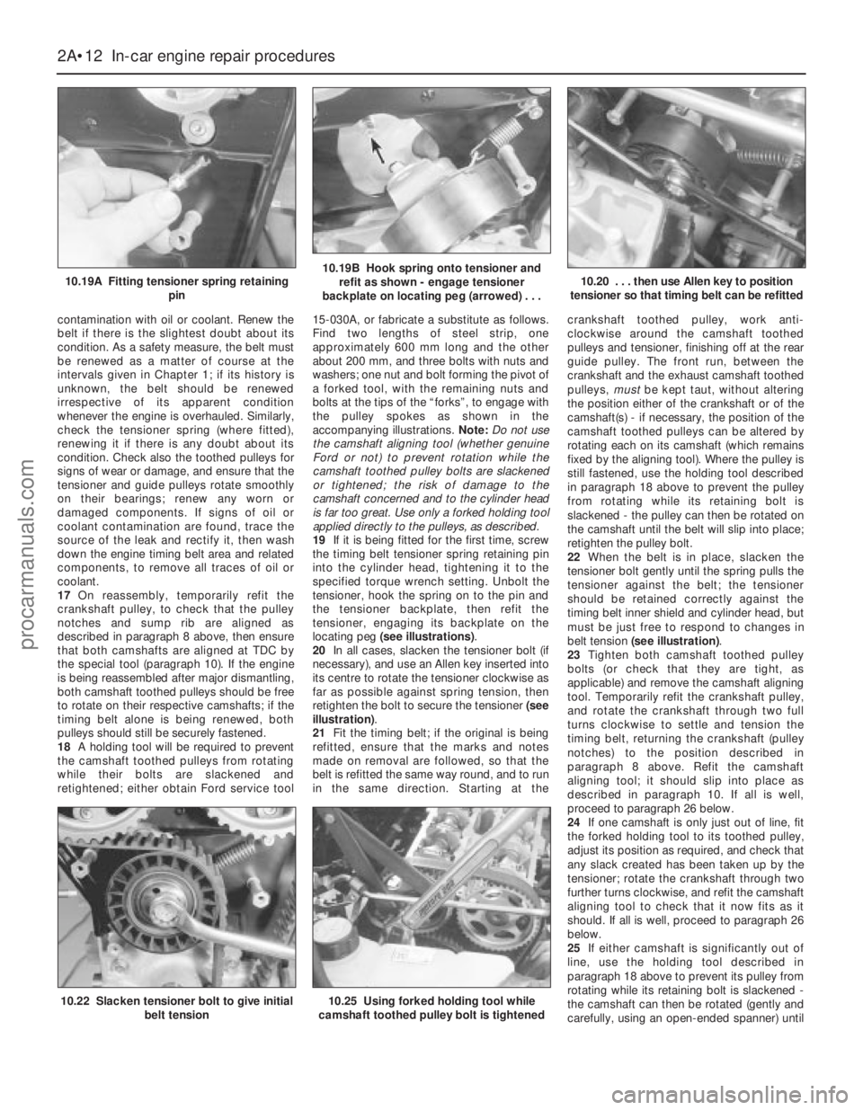
19If it is being fitted for the first time, screw
the timing belt tensioner spring retaining pin
into the cylinder head, tightening it to the
specified torque wrench setting. Unbolt the
tensioner, hook the spring on to the pin and
the tensioner backplate, then refit the
tensioner, engaging its backplate on the
locating peg (see illustrations).
20In all cases, slacken the tensioner bolt (if
necessary), and use an Allen key inserted into
its centre to rotate the tensioner clockwise as
far as possible against spring tension, then
retighten the bolt to secure the tensioner (see
illustration).
21Fit the timing belt; if the original is being
refitted, ensure that the marks and notes
made on removal are followed, so that the
belt is refitted the same way round, and to run
in the same direction. Starting at thecrankshaft toothed pulley, work anti-
clockwise around the camshaft toothed
pulleys and tensioner, finishing off at the rear
guide pulley. The front run, between the
crankshaft and the exhaust camshaft toothed
pulleys, mustbe kept taut, without altering
the position either of the crankshaft or of the
camshaft(s) - if necessary, the position of the
camshaft toothed pulleys can be altered by
rotating each on its camshaft (which remains
fixed by the aligning tool). Where the pulley is
still fastened, use the holding tool described
in paragraph 18 above to prevent the pulley
from rotating while its retaining bolt is
slackened - the pulley can then be rotated on
the camshaft until the belt will slip into place;
retighten the pulley bolt.
22When the belt is in place, slacken the
tensioner bolt gently until the spring pulls the
tensioner against the belt; the tensioner
should be retained correctly against the
timing belt inner shield and cylinder head, but
must be just free to respond to changes in
belt tension (see illustration).
23Tighten both camshaft toothed pulley
bolts (or check that they are tight, as
applicable) and remove the camshaft aligning
tool. Temporarily refit the crankshaft pulley,
and rotate the crankshaft through two full
turns clockwise to settle and tension the
timing belt, returning the crankshaft (pulley
notches) to the position described in
paragraph 8 above. Refit the camshaft
aligning tool; it should slip into place as
described in paragraph 10. If all is well,
proceed to paragraph 26 below.
24If one camshaft is only just out of line, fit
the forked holding tool to its toothed pulley,
adjust its position as required, and check that
any slack created has been taken up by the
tensioner; rotate the crankshaft through two
further turns clockwise, and refit the camshaft
aligning tool to check that it now fits as it
should. If all is well, proceed to paragraph 26
below.
25If either camshaft is significantly out of
line, use the holding tool described in
paragraph 18 above to prevent its pulley from
rotating while its retaining bolt is slackened -
the camshaft can then be rotated (gently and
carefully, using an open-ended spanner) until
2A•12 In-car engine repair procedures
10.19A Fitting tensioner spring retaining
pin10.19B Hook spring onto tensioner and
refit as shown - engage tensioner
backplate on locating peg (arrowed) . . .10.20 . . . then use Allen key to position
tensioner so that timing belt can be refitted
10.22 Slacken tensioner bolt to give initial
belt tension10.25 Using forked holding tool while
camshaft toothed pulley bolt is tightened
procarmanuals.com
Page 53 of 279
the camshaft aligning tool will slip into place;
take care not to disturb the relationship of the
pulley to the timing belt. Without disturbing
the pulley’s new position on the camshaft,
tighten the pulley bolt to its specified torque
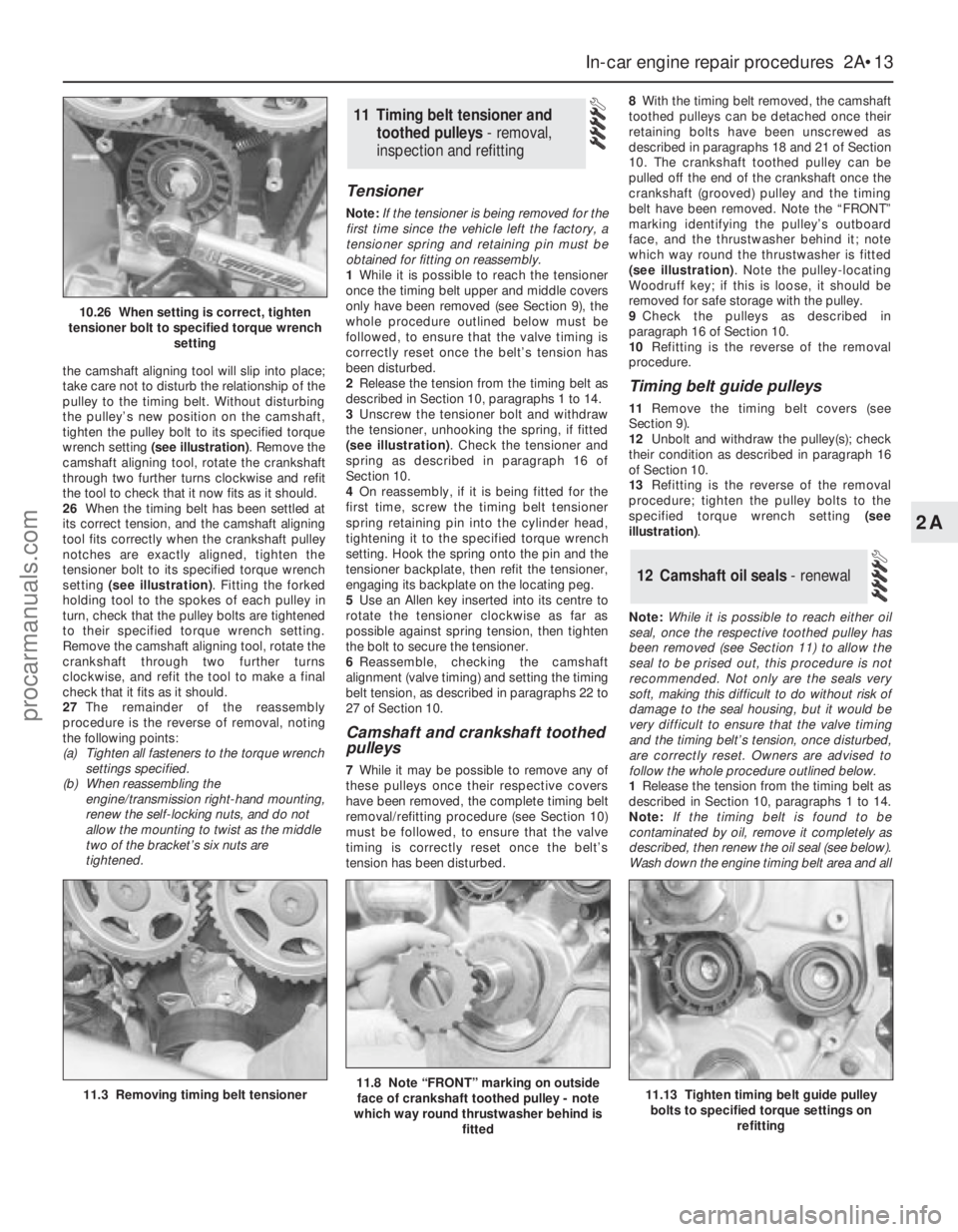
wrench setting (see illustration). Remove the
camshaft aligning tool, rotate the crankshaft
through two further turns clockwise and refit
the tool to check that it now fits as it should.
26When the timing belt has been settled at
its correct tension, and the camshaft aligning
tool fits correctly when the crankshaft pulley
notches are exactly aligned, tighten the
tensioner bolt to its specified torque wrench
setting (see illustration). Fitting the forked
holding tool to the spokes of each pulley in
turn, check that the pulley bolts are tightened
to their specified torque wrench setting.
Remove the camshaft aligning tool, rotate the
crankshaft through two further turns
clockwise, and refit the tool to make a final
check that it fits as it should.
27The remainder of the reassembly
procedure is the reverse of removal, noting
the following points:
(a) Tighten all fasteners to the torque wrench
settings specified.
(b) When reassembling the
engine/transmission right-hand mounting,
renew the self-locking nuts, and do not
allow the mounting to twist as the middle
two of the bracket’s six nuts are
tightened.
Tensioner
Note:If the tensioner is being removed for the
first time since the vehicle left the factory, a
tensioner spring and retaining pin must be
obtained for fitting on reassembly.
1While it is possible to reach the tensioner
once the timing belt upper and middle covers
only have been removed (see Section 9), the
whole procedure outlined below must be
followed, to ensure that the valve timing is
correctly reset once the belt’s tension has
been disturbed.
2Release the tension from the timing belt as
described in Section 10, paragraphs 1 to 14.
3Unscrew the tensioner bolt and withdraw
the tensioner, unhooking the spring, if fitted
(see illustration). Check the tensioner and
spring as described in paragraph 16 of
Section 10.
4On reassembly, if it is being fitted for the
first time, screw the timing belt tensioner
spring retaining pin into the cylinder head,
tightening it to the specified torque wrench
setting. Hook the spring onto the pin and the
tensioner backplate, then refit the tensioner,
engaging its backplate on the locating peg.
5Use an Allen key inserted into its centre to
rotate the tensioner clockwise as far as
possible against spring tension, then tighten
the bolt to secure the tensioner.
6Reassemble, checking the camshaft
alignment (valve timing) and setting the timing
belt tension, as described in paragraphs 22 to
27 of Section 10.
Camshaft and crankshaft toothed
pulleys
7While it may be possible to remove any of
these pulleys once their respective covers
have been removed, the complete timing belt
removal/refitting procedure (see Section 10)
must be followed, to ensure that the valve
timing is correctly reset once the belt’s
tension has been disturbed.8With the timing belt removed, the camshaft
toothed pulleys can be detached once their
retaining bolts have been unscrewed as
described in paragraphs 18 and 21 of Section
10. The crankshaft toothed pulley can be
pulled off the end of the crankshaft once the
crankshaft (grooved) pulley and the timing
belt have been removed. Note the “FRONT”
marking identifying the pulley’s outboard
face, and the thrustwasher behind it; note
which way round the thrustwasher is fitted
(see illustration). Note the pulley-locating
Woodruff key; if this is loose, it should be
removed for safe storage with the pulley.
9Check the pulleys as described in
paragraph 16 of Section 10.
10Refitting is the reverse of the removal
procedure.
Timing belt guide pulleys
11Remove the timing belt covers (see
Section 9).
12Unbolt and withdraw the pulley(s); check
their condition as described in paragraph 16
of Section 10.
13Refitting is the reverse of the removal
procedure; tighten the pulley bolts to the
specified torque wrench setting (see
illustration).
Note:While it is possible to reach either oil
seal, once the respective toothed pulley has
been removed (see Section 11) to allow the
seal to be prised out, this procedure is not
recommended. Not only are the seals very
soft, making this difficult to do without risk of
damage to the seal housing, but it would be
very difficult to ensure that the valve timing
and the timing belt’s tension, once disturbed,
are correctly reset. Owners are advised to
follow the whole procedure outlined below.
1Release the tension from the timing belt as
described in Section 10, paragraphs 1 to 14.
Note:If the timing belt is found to be
contaminated by oil, remove it completely as
described, then renew the oil seal (see below).
Wash down the engine timing belt area and all
12 Camshaft oil seals - renewal
11 Timing belt tensioner and
toothed pulleys - removal,
inspection and refitting
In-car engine repair procedures 2A•13
2A
11.3 Removing timing belt tensioner11.8 Note “FRONT” marking on outside
face of crankshaft toothed pulley - note
which way round thrustwasher behind is
fitted11.13 Tighten timing belt guide pulley
bolts to specified torque settings on
refitting
10.26 When setting is correct, tighten
tensioner bolt to specified torque wrench
setting
procarmanuals.com
Page 58 of 279
14Unscrew the two nuts to disconnect the
exhaust system front downpipe from the
manifold (Chapter 4); disconnect the oxygen
sensor wiring, so that it is not strained by the
weight of the exhaust system.
15Remove the auxiliary drivebelt (see
Chapter 1).
16Support the weight of the
engine/transmission using a trolley jack, with
a wooden spacer to prevent damage to the
sump.
17Unscrew the six nuts securing the
engine/transmission right-hand mounting
bracket, then withdraw the bracket. Unbolt
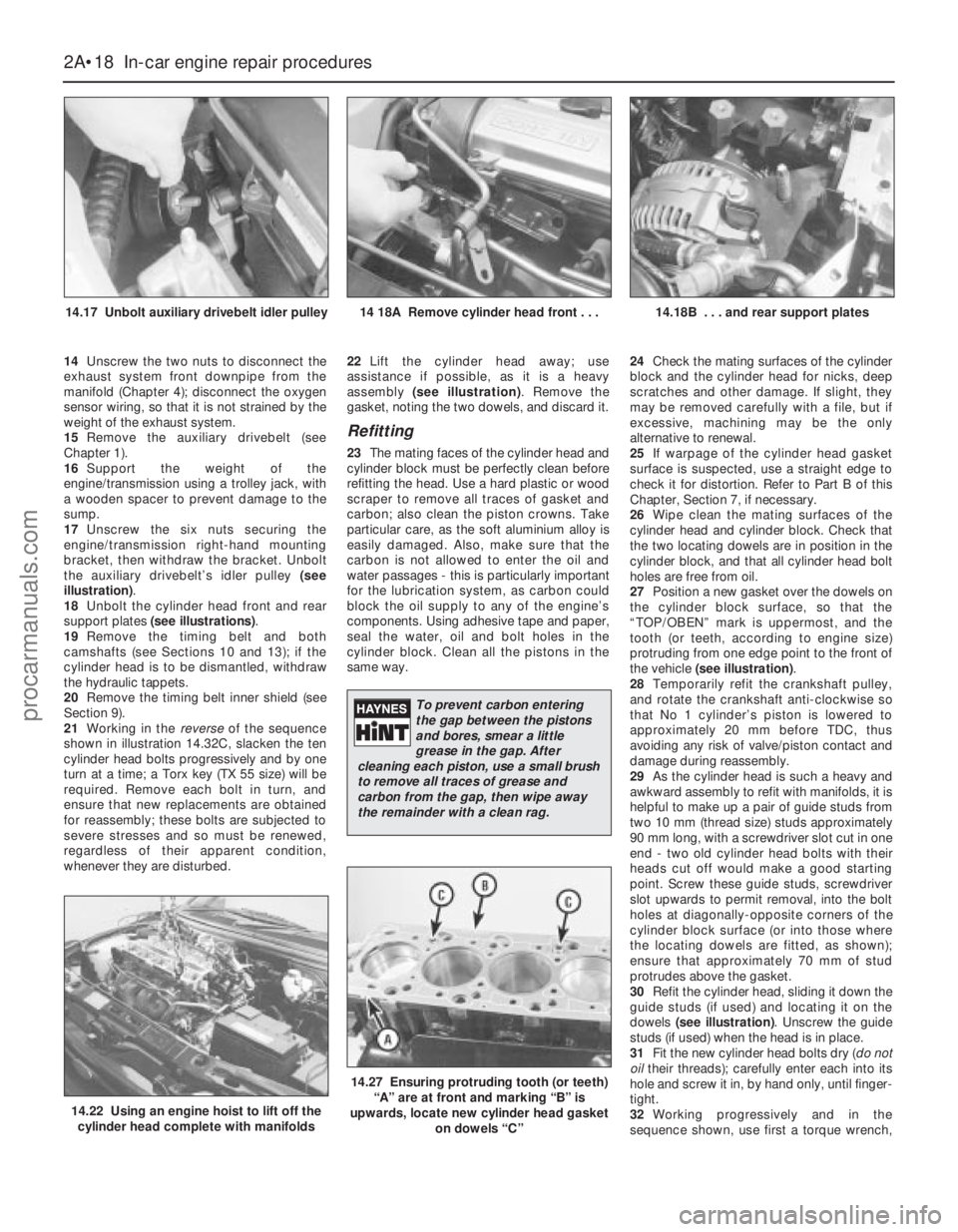
the auxiliary drivebelt’s idler pulley (see
illustration).
18Unbolt the cylinder head front and rear
support plates (see illustrations).
19Remove the timing belt and both
camshafts (see Sections 10 and 13); if the
cylinder head is to be dismantled, withdraw
the hydraulic tappets.
20Remove the timing belt inner shield (see
Section 9).
21Working in the reverseof the sequence
shown in illustration 14.32C, slacken the ten
cylinder head bolts progressively and by one
turn at a time; a Torx key (TX 55 size) will be
required. Remove each bolt in turn, and
ensure that new replacements are obtained
for reassembly; these bolts are subjected to
severe stresses and so must be renewed,
regardless of their apparent condition,
whenever they are disturbed.22Lift the cylinder head away; use
assistance if possible, as it is a heavy
assembly (see illustration). Remove the
gasket, noting the two dowels, and discard it.
Refitting
23The mating faces of the cylinder head and
cylinder block must be perfectly clean before
refitting the head. Use a hard plastic or wood
scraper to remove all traces of gasket and
carbon; also clean the piston crowns. Take
particular care, as the soft aluminium alloy is
easily damaged. Also, make sure that the
carbon is not allowed to enter the oil and
water passages - this is particularly important
for the lubrication system, as carbon could
block the oil supply to any of the engine’s
components. Using adhesive tape and paper,
seal the water, oil and bolt holes in the
cylinder block. Clean all the pistons in the
same way.24Check the mating surfaces of the cylinder
block and the cylinder head for nicks, deep
scratches and other damage. If slight, they
may be removed carefully with a file, but if
excessive, machining may be the only
alternative to renewal.
25If warpage of the cylinder head gasket
surface is suspected, use a straight edge to
check it for distortion. Refer to Part B of this
Chapter, Section 7, if necessary.
26Wipe clean the mating surfaces of the
cylinder head and cylinder block. Check that
the two locating dowels are in position in the
cylinder block, and that all cylinder head bolt
holes are free from oil.
27Position a new gasket over the dowels on
the cylinder block surface, so that the
“TOP/OBEN” mark is uppermost, and the
tooth (or teeth, according to engine size)
protruding from one edge point to the front of
the vehicle (see illustration).
28Temporarily refit the crankshaft pulley,
and rotate the crankshaft anti-clockwise so
that No 1 cylinder’s piston is lowered to
approximately 20 mm before TDC, thus
avoiding any risk of valve/piston contact and
damage during reassembly.
29As the cylinder head is such a heavy and
awkward assembly to refit with manifolds, it is
helpful to make up a pair of guide studs from
two 10 mm (thread size) studs approximately
90 mm long, with a screwdriver slot cut in one
end - two old cylinder head bolts with their
heads cut off would make a good starting
point. Screw these guide studs, screwdriver
slot upwards to permit removal, into the bolt
holes at diagonally-opposite corners of the
cylinder block surface (or into those where
the locating dowels are fitted, as shown);
ensure that approximately 70 mm of stud
protrudes above the gasket.
30Refit the cylinder head, sliding it down the
guide studs (if used) and locating it on the
dowels (see illustration). Unscrew the guide
studs (if used) when the head is in place.
31Fit the new cylinder head bolts dry (do not
oiltheir threads); carefully enter each into its
hole and screw it in, by hand only, until finger-
tight.
32Working progressively and in the
sequence shown, use first a torque wrench,
2A•18 In-car engine repair procedures
14.17 Unbolt auxiliary drivebelt idler pulley14 18A Remove cylinder head front . . .14.18B . . . and rear support plates
14.22 Using an engine hoist to lift off the
cylinder head complete with manifolds
14.27 Ensuring protruding tooth (or teeth)
“A” are at front and marking “B” is
upwards, locate new cylinder head gasket
on dowels “C”
To prevent carbon entering
the gap between the pistons
and bores, smear a little
grease in the gap. After
cleaning each piston, use a small brush
to remove all traces of grease and
carbon from the gap, then wipe away
the remainder with a clean rag.
procarmanuals.com
Page 112 of 279
General information
The engine electrical systems include all
ignition, charging and starting components.
Because of their engine-related functions,
these components are discussed separately
from body electrical devices such as the
lights, the instruments, etc (which are
included in Chapter 12).
Precautions
Always observe the following precautions
when working on the electrical system:
(a) Be extremely careful when servicing
engine electrical components. They are
easily damaged if checked, connected or
handled improperly.
(b) Never leave the ignition switched on for
long periods of time when the engine is
not running.
(c) Don’t disconnect the battery leads while
the engine is running.
(d) Maintain correct polarity when connecting
a battery lead from another vehicle during
jump starting - see the “Booster battery
(jump) starting” section at the front of this
manual.
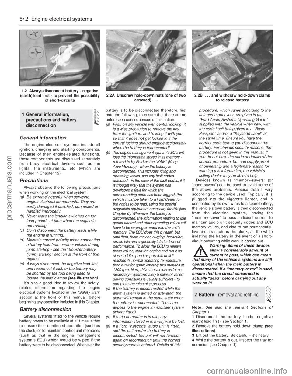
(e) Always disconnect the negative lead first,
and reconnect it last, or the battery may
be shorted by the tool being used to
loosen the lead clamps (see illustration).
It’s also a good idea to review the safety-
related information regarding the engine
electrical systems located in the “Safety first!”
section at the front of this manual, before
beginning any operation included in this Chapter.
Battery disconnection
Several systems fitted to the vehicle require
battery power to be available at all times, either
to ensure their continued operation (such as
the clock) or to maintain control unit memories
(such as that in the engine management
system’s ECU) which would be wiped if the
battery were to be disconnected. Whenever thebattery is to be disconnected therefore, first
note the following, to ensure that there are no
unforeseen consequences of this action:
(a) First, on any vehicle with central locking, it
is a wise precaution to remove the key
from the ignition, and to keep it with you,
so that it does not get locked in if the
central locking should engage accidentally
when the battery is reconnected!
(b) The engine management system’s ECU will
lose the information stored in its memory -
referred to by Ford as the “KAM” (Keep-
Alive Memory) - when the battery is
disconnected. This includes idling and
operating values, and any fault codes
detected - in the case of the fault codes, if it
is thought likely that the system has
developed a fault for which the
corresponding code has been logged, the
vehicle must be taken to a Ford dealer for
the codes to be read, using the special
diagnostic equipment necessary for this (see
Chapter 6). Whenever the battery is
disconnected, the information relating to idle
speed control and other operating values will
have to be re-programmed into the unit’s
memory. The ECU does this by itself, but
until then, there may be surging, hesitation,
erratic idle and a generally inferior level of
performance. To allow the ECU to relearn
these values, start the engine and run it as
close to idle speed as possible until it
reaches its normal operating temperature,
then run it for approximately two minutes at
1200 rpm. Next, drive the vehicle as far as
necessary - approximately 5 miles of varied
driving conditions is usually sufficient - to
complete the relearning process.
(c) If the battery is disconnected while the
alarm system is armed or activated, the
alarm will remain in the same state when
the battery is reconnected. The same
applies to the engine immobiliser system
(where fitted).
(d) If a trip computer is in use, any
information stored in memory will be lost.
(e) If a Ford “Keycode” audio unit is fitted,
and the unit and/or the battery is
disconnected, the unit will not function
again on reconnection until the correct
security code is entered. Details of thisprocedure, which varies according to the
unit and model year, are given in the
“Ford Audio Systems Operating Guide”
supplied with the vehicle when new, with
the code itself being given in a “Radio
Passport” and/or a “Keycode Label” at
the same time. Ensure you have the
correct code before you disconnect the
battery. For obvious security reasons, the
procedure is not given in this manual. If
you do not have the code or details of the
correct procedure, but can supply proof
of ownership and a legitimate reason for
wanting this information, the vehicle’s
selling dealer may be able to help.
Devices known as “memory-savers” (or
“code-savers”) can be used to avoid some of
the above problems. Precise details vary
according to the device used. Typically, it is
plugged into the cigarette lighter, and is
connected by its own wires to a spare battery;
the vehicle’s own battery is then disconnected
from the electrical system, leaving the
“memory-saver” to pass sufficient current to
maintain audio unit security codes and ECU
memory values, and also to run permanently-
live circuits such as the clock, all the while
isolating the battery in the event of a short-
circuit occurring while work is carried out.
Warning: Some of these devices
allow a considerable amount of
current to pass, which can mean
that many of the vehicle’s systems are still
operational when the main battery is
disconnected. If a “memory-saver” is used,
ensure that the circuit concerned is
actually “dead” before carrying out any
work on it!
Note:See also the relevant Sections of
Chapter 1.
1Disconnect the battery leads, negative
(earth) lead first - see Section 1.
2Remove the battery hold-down clamp (see
illustrations).
3Lift out the battery. Be careful - it’s heavy.
4While the battery is out, inspect the tray for
corrosion (see Chapter 1).
2 Battery- removal and refitting
1 General information,
precautions and battery
disconnection
5•2 Engine electrical systems
1.2 Always disconnect battery - negative
(earth) lead first - to prevent the possibility
of short-circuits2.2A Unscrew hold-down nuts (one of two
arrowed) . . .2.2B . . . and withdraw hold-down clamp
to release battery
procarmanuals.com