1993 FORD MONDEO battery replacement
[x] Cancel search: battery replacementPage 45 of 279
The cylinder head is provided with two oil
galleries, one on the inlet side and one on the
exhaust, to ensure constant oil supply to the
camshaft bearings and hydraulic tappets. A
retaining valve (inserted into the cylinder
head’s top surface, in the middle, on the inlet
side) prevents these galleries from being
drained when the engine is switched off. The
valve incorporates a ventilation hole in its
upper end, to allow air bubbles to escape
from the system when the engine is restarted.
While the crankshaft and camshaft
bearings and the hydraulic tappets receive a
pressurised supply, the camshaft lobes and
valves are lubricated by splash, as are all
other engine components.
Valve clearances - general
It is necessary for a clearance to exist
between the tip of each valve stem and the
valve operating mechanism, to allow for the
expansion of the various components as the
engine reaches normal operating
temperature.
On most older engine designs, this meant
that the valve clearances (also known as
“tappet” clearances) had to be checked and
adjusted regularly. If the clearances were
allowed to be too slack, the engine would be
very noisy, its power output would suffer, and
its fuel consumption would increase. If the
clearances were allowed to be too tight, the
engine’s power output would be reduced,
and the valves and their seats could be
severely damaged.
The engines covered in this manual,
however, employ hydraulic tappets which use
the lubricating system’s oil pressure
automatically to take up the clearance
between each camshaft lobe and its
respective valve stem. Therefore, there is no
need for regular checking and adjustment of
the valve clearances, but it is essential that
onlygood-quality oil of the recommended
viscosity and specification is used in the
engine, and that this oil is always changed at
the recommended intervals. If this advice is
not followed, the oilways and tappets may
become clogged with particles of dirt, or
deposits of burnt (inferior) engine oil, so that
the system cannot work properly; ultimately,
one or more of the tappets may fail, and
expensive repairs may be required.
On starting the engine from cold, there will
be a slight delay while full oil pressure builds
up in all parts of the engine, especially in the
tappets; the valve components, therefore,
may well “rattle” for about 10 seconds or so,
and then quieten. This is a normal state of
affairs, and is nothing to worry about,
provided that all tappets quieten quickly and
stay quiet.
After the vehicle has been standing for
several days, the valve components may
“rattle” for longer than usual, as nearly all the
oil will have drained away from the engine’s
top end components and bearing surfaces.
While this is only to be expected, care mustbe taken not to damage the engine under
these circumstances - avoid high speed
running until all the tappets are refilled with oil
and operating normally. With the vehicle
stationary, hold the engine at no more than a
fast idle speed (maximum 2000 to 2500 rpm)
for 10 to 15 seconds, or until the noise
ceases. Do not run the engine at more than
3000 rpm until the tappets are fully recharged
with oil and the noise has ceased.
If the valve components are thought to be
noisy, or if a light rattle persists from the top
end after the engine has warmed up to
normal operating temperature, take the
vehicle to a Ford dealer for expert advice.
Depending on the mileage covered and the
usage to which each vehicle has been put,
some vehicles may be noisier than others;
only a good mechanic experienced in these
engines can tell if the noise level is typical for
the vehicle’s mileage, or if a genuine fault
exists. If any tappet’s operation is faulty, it
must be renewed (Section 13).
The following major repair operations can
be accomplished without removing the
engine from the vehicle. However, owners
should note that any operation involving the
removal of the sump requires careful
forethought, depending on the level of skill
and the tools and facilities available; refer to
the relevant text for details.
(a) Compression pressure - testing.
(b) Cylinder head cover - removal and
refitting.
(c) Timing belt covers - removal and refitting.
(d) Timing belt - renewal.
(e) Timing belt tensioner and toothed pulleys
- removal and refitting.
(f) Camshaft oil seals - renewal.
(g) Camshafts and hydraulic tappets -
removal and refitting.
(h) Cylinder head - removal, overhaul and
refitting.
(i) Cylinder head and pistons -
decarbonising.
(j) Sump - removal and refitting.
(k) Crankshaft oil seals - renewal.
(l) Oil pump - removal and refitting.
(m) Piston/connecting rod assemblies -
removal and refitting (but see note below).
(n) Flywheel/driveplate - removal and
refitting.
(o) Engine/transmission mountings - removal
and refitting.
Clean the engine compartment and the
exterior of the engine with some type of
degreaser before any work is done. It will
make the job easier, and will help to keep dirt
out of the internal areas of the engine.
Depending on the components involved, it
may be helpful to remove the bonnet, to
improve access to the engine as repairs are
performed (refer to Chapter 11 if necessary).Cover the wings to prevent damage to the
paint; special covers are available, but an old
bedspread or blanket will also work.
If vacuum, exhaust, oil or coolant leaks
develop, indicating a need for component/
gasket or seal replacement, the repairs can
generally be made with the engine in the
vehicle. The intake and exhaust manifold
gaskets, sump gasket, crankshaft oil seals
and cylinder head gasket are all accessible
with the engine in place.
Exterior components such as the intake
and exhaust manifolds, the sump, the oil
pump, the water pump, the starter motor, the
alternator and the fuel system components
can be removed for repair with the engine in
place.
Since the cylinder head can be removed
without lifting out the engine, camshaft and
valve component servicing can also be
accomplished with the engine in the vehicle,
as can renewal of the timing belt and toothed
pulleys.
In extreme cases caused by a lack of
necessary equipment, repair or renewal of
piston rings, pistons, connecting rods and
big-end bearings is possible with the engine
in the vehicle. However, this practice is not
recommended, because of the cleaning and
preparation work that must be done to the
components involved, and because of the
amount of preliminary dismantling work
required - these operations are therefore
covered in Part B of this Chapter.
1When engine performance is down, or if
misfiring occurs which cannot be attributed to
the ignition or fuel systems, a compression
test can provide diagnostic clues as to the
engine’s condition. If the test is performed
regularly, it can give warning of trouble before
any other symptoms become apparent.
2The engine must be fully warmed-up to
normal operating temperature, the oil level
must be correct, the battery must be fully
charged, and the spark plugs must be
removed. The aid of an assistant will be
required also.
3Disable the ignition system by unplugging
the ignition coil’s electrical connector, and
remove fuse 14 to disconnect the fuel pump.
4Fit a compression tester to the No 1
cylinder spark plug hole - the type of tester
which screws into the plug thread is to be
preferred.
5Have the assistant hold the throttle wide
open and crank the engine on the starter
motor; after one or two revolutions, the
compression pressure should build up to a
maximum figure, and then stabilise. Record
the highest reading obtained.
6Repeat the test on the remaining cylinders,
recording the pressure developed in each.
7At the time of writing, no compression
3 Compression test -
description and interpretation
2 Repair operations possible with
the engine in the vehicle
In-car engine repair procedures 2A•5
2A
procarmanuals.com
Page 101 of 279
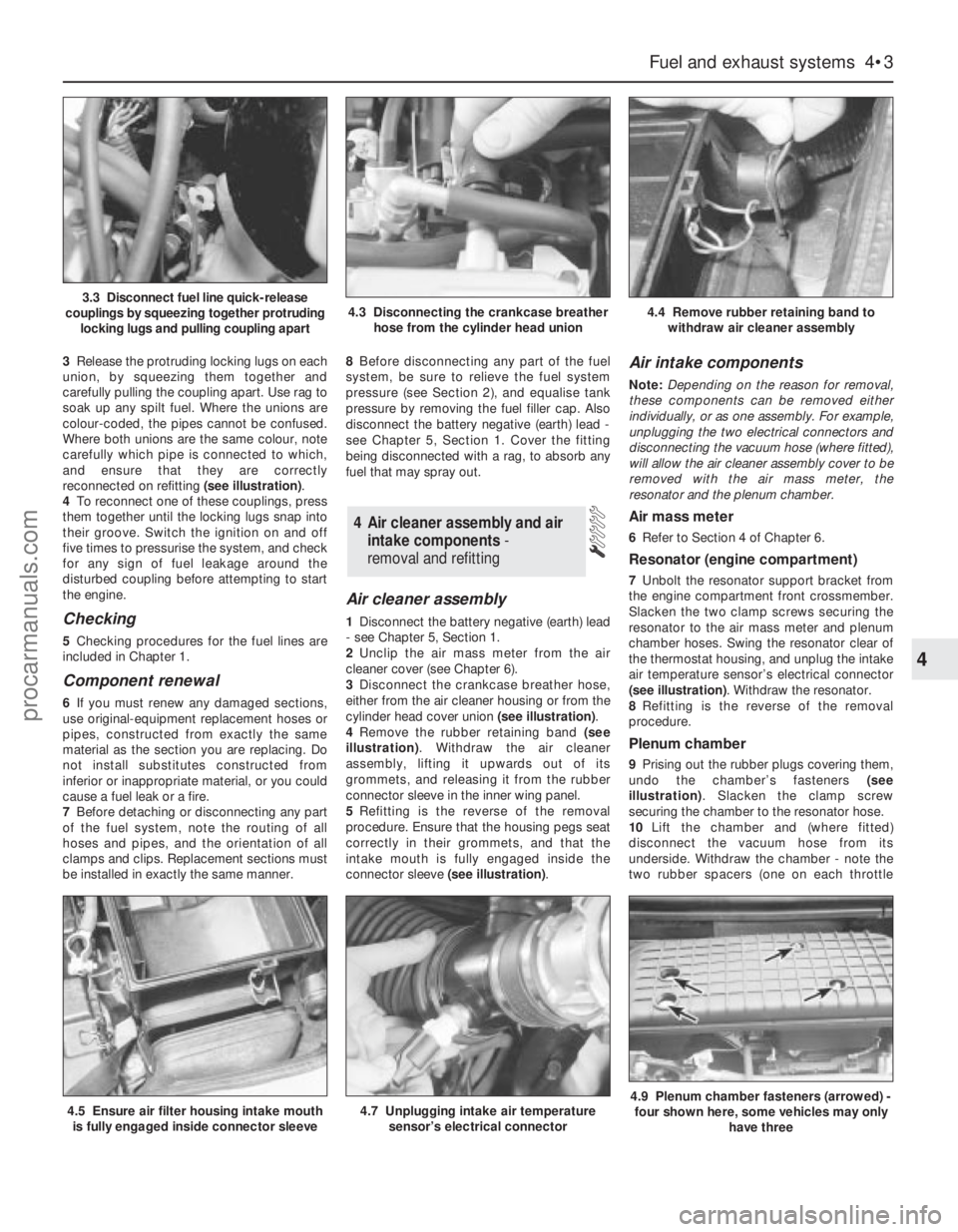
3Release the protruding locking lugs on each
union, by squeezing them together and
carefully pulling the coupling apart. Use rag to
soak up any spilt fuel. Where the unions are
colour-coded, the pipes cannot be confused.
Where both unions are the same colour, note
carefully which pipe is connected to which,
and ensure that they are correctly
reconnected on refitting (see illustration).
4To reconnect one of these couplings, press
them together until the locking lugs snap into
their groove. Switch the ignition on and off
five times to pressurise the system, and check
for any sign of fuel leakage around the
disturbed coupling before attempting to start
the engine.
Checking
5Checking procedures for the fuel lines are
included in Chapter 1.
Component renewal
6If you must renew any damaged sections,
use original-equipment replacement hoses or
pipes, constructed from exactly the same
material as the section you are replacing. Do
not install substitutes constructed from
inferior or inappropriate material, or you could
cause a fuel leak or a fire.
7Before detaching or disconnecting any part
of the fuel system, note the routing of all
hoses and pipes, and the orientation of all
clamps and clips. Replacement sections must
be installed in exactly the same manner.8Before disconnecting any part of the fuel
system, be sure to relieve the fuel system
pressure (see Section 2), and equalise tank
pressure by removing the fuel filler cap. Also
disconnect the battery negative (earth) lead -
see Chapter 5, Section 1. Cover the fitting
being disconnected with a rag, to absorb any
fuel that may spray out.
Air cleaner assembly
1Disconnect the battery negative (earth) lead
- see Chapter 5, Section 1.
2Unclip the air mass meter from the air
cleaner cover (see Chapter 6).
3Disconnect the crankcase breather hose,
either from the air cleaner housing or from the
cylinder head cover union (see illustration).
4Remove the rubber retaining band (see
illustration). Withdraw the air cleaner
assembly, lifting it upwards out of its
grommets, and releasing it from the rubber
connector sleeve in the inner wing panel.
5Refitting is the reverse of the removal
procedure. Ensure that the housing pegs seat
correctly in their grommets, and that the
intake mouth is fully engaged inside the
connector sleeve (see illustration).
Air intake components
Note:Depending on the reason for removal,
these components can be removed either
individually, or as one assembly. For example,
unplugging the two electrical connectors and
disconnecting the vacuum hose (where fitted),
will allow the air cleaner assembly cover to be
removed with the air mass meter, the
resonator and the plenum chamber.
Air mass meter
6Refer to Section 4 of Chapter 6.
Resonator (engine compartment)
7Unbolt the resonator support bracket from
the engine compartment front crossmember.
Slacken the two clamp screws securing the
resonator to the air mass meter and plenum
chamber hoses. Swing the resonator clear of
the thermostat housing, and unplug the intake
air temperature sensor’s electrical connector
(see illustration). Withdraw the resonator.
8Refitting is the reverse of the removal
procedure.
Plenum chamber
9Prising out the rubber plugs covering them,
undo the chamber’s fasteners (see
illustration). Slacken the clamp screw
securing the chamber to the resonator hose.
10Lift the chamber and (where fitted)
disconnect the vacuum hose from its
underside. Withdraw the chamber - note the
two rubber spacers (one on each throttle
4 Air cleaner assembly and air
intake components -
removal and refitting
Fuel and exhaust systems 4•3
4
4.5 Ensure air filter housing intake mouth
is fully engaged inside connector sleeve4.7 Unplugging intake air temperature
sensor’s electrical connector4.9 Plenum chamber fasteners (arrowed) -
four shown here, some vehicles may only
have three
3.3 Disconnect fuel line quick-release
couplings by squeezing together protruding
locking lugs and pulling coupling apart4.3 Disconnecting the crankcase breather
hose from the cylinder head union4.4 Remove rubber retaining band to
withdraw air cleaner assembly
procarmanuals.com
Page 110 of 279
Idle-increase solenoid valve
Check
43If this valve is thought to be faulty, unplug
its electrical connector and disconnect its
vacuum hoses, then connect a battery directly
across the valve’s terminals. Check that air
can flow through the valve’s passages when
the solenoid is energised, and that nothing
can pass when the solenoid is not energised.
Alternatively, connect an ohmmeter to
measure the resistance between the valve’s
terminals, and compare this reading to that
listed in the Specifications Section at the
beginning of this Chapter. Renew the valve if
it is faulty (see illustration).
44The solenoid’s diode is fitted to control
any voltage “spikes” which might occur as the
solenoid is switched off. A faulty diode would
not, therefore, necessarily interfere with the
operation of the valve. If the diode is thought
to be faulty, however, it can be checked by
unplugging it and connecting an ohmmeter
across its terminals, to check that continuity
exists in one direction only. If continuity is
found in both directions, or in neither, the
diode is faulty, and must be renewed.
Renewal
45If better access is required, remove the
plenum chamber (see Section 4).
46Disconnect the battery negative (earth)
lead - see Section 1 of Chapter 5.
46Unplug the valve’s electrical connector.
Unclip the valve from the bulkhead, then
disconnect its vacuum hoses and withdraw it.
47Refitting is the reverse of the removal
procedure.
Warning: Inspection and repair of
exhaust system components
should be done only after enough
time has elapsed after driving the vehicle
to allow the system components to cool
completely. This applies particularly to the
catalytic converter, which runs at very
high temperatures. Also, when working
under the vehicle, make sure it is securely
supported on axle stands.
1The exhaust system is composed of an
exhaust manifold, the front downpipe and
catalytic converter, and a rear section
incorporating two silencers (three on some
versions) and the tailpipe assembly. The
service replacement exhaust system consists
of three or four sections: the front
downpipe/catalytic converter, the
intermediate pipe and front silencer, and the
tailpipe and rear silencer. On some versions,
the tailpipe is in two pieces, with two rear
silencers. The system is suspended
throughout its entire length by rubber
mountings.
2If any of these parts are damaged ordeteriorated, excessive noise and vibration
will occur.
3Conduct regular inspections of the exhaust
system, to keep it safe and quiet. Look for any
damaged or bent parts, open seams, holes,
loose connections, excessive corrosion, or
other defects which could allow exhaust
fumes to enter the vehicle. Deteriorated
exhaust system components should not be
repaired - they should be replaced with new
parts.
4If the exhaust system components are
extremely corroded or rusted together, they
will probably have to be cut from the exhaust
system. The most convenient way of
accomplishing this is to have a quick-fit
exhaust repair specialist remove the corroded
sections. If, however, you want to save money
by doing it yourself (and you don’t have an
oxy/acetylene welding outfit with a cutting
torch), simply cut off the old components with
a hacksaw. If you have compressed air,
special pneumatic cutting chisels can also be
used. If you do decide to tackle the job at
home, be sure to wear eye protection, to
protect your eyes from metal chips, and work
gloves, to protect your hands. If the
production-fit system is still fitted, it must be
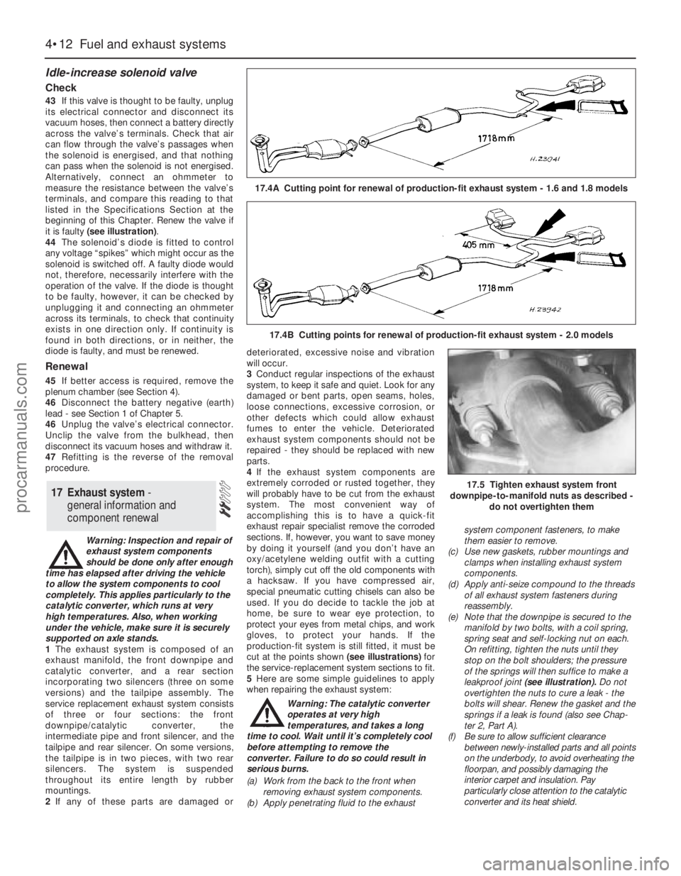
cut at the points shown (see illustrations) for
the service-replacement system sections to fit.
5Here are some simple guidelines to apply
when repairing the exhaust system:
Warning: The catalytic converter
operates at very high
temperatures, and takes a long
time to cool. Wait until it’s completely cool
before attempting to remove the
converter. Failure to do so could result in
serious burns.
(a) Work from the back to the front when
removing exhaust system components.
(b) Apply penetrating fluid to the exhaustsystem component fasteners, to make
them easier to remove.
(c) Use new gaskets, rubber mountings and
clamps when installing exhaust system
components.
(d) Apply anti-seize compound to the threads
of all exhaust system fasteners during
reassembly.
(e) Note that the downpipe is secured to the
manifold by two bolts, with a coil spring,
spring seat and self-locking nut on each.
On refitting, tighten the nuts until they
stop on the bolt shoulders; the pressure
of the springs will then suffice to make a
leakproof joint (see illustration). Do not
overtighten the nuts to cure a leak - the
bolts will shear. Renew the gasket and the
springs if a leak is found (also see Chap-
ter 2, Part A).
(f) Be sure to allow sufficient clearance
between newly-installed parts and all points
on the underbody, to avoid overheating the
floorpan, and possibly damaging the
interior carpet and insulation. Pay
particularly close attention to the catalytic
converter and its heat shield.
17 Exhaust system -
general information and
component renewal
4•12 Fuel and exhaust systems
17.4A Cutting point for renewal of production-fit exhaust system - 1.6 and 1.8 models
17.4B Cutting points for renewal of production-fit exhaust system - 2.0 models
17.5 Tighten exhaust system front
downpipe-to-manifold nuts as described -
do not overtighten them
procarmanuals.com
Page 116 of 279
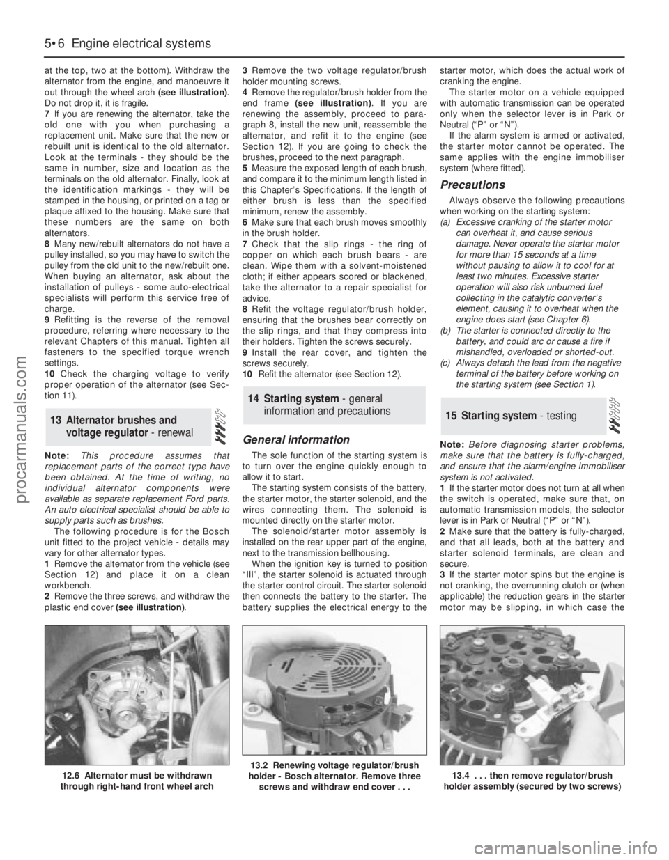
at the top, two at the bottom). Withdraw the
alternator from the engine, and manoeuvre it
out through the wheel arch (see illustration).
Do not drop it, it is fragile.
7If you are renewing the alternator, take the
old one with you when purchasing a
replacement unit. Make sure that the new or
rebuilt unit is identical to the old alternator.
Look at the terminals - they should be the
same in number, size and location as the
terminals on the old alternator. Finally, look at
the identification markings - they will be
stamped in the housing, or printed on a tag or
plaque affixed to the housing. Make sure that
these numbers are the same on both
alternators.
8Many new/rebuilt alternators do not have a
pulley installed, so you may have to switch the
pulley from the old unit to the new/rebuilt one.
When buying an alternator, ask about the
installation of pulleys - some auto-electrical
specialists will perform this service free of
charge.
9Refitting is the reverse of the removal
procedure, referring where necessary to the
relevant Chapters of this manual. Tighten all
fasteners to the specified torque wrench
settings.
10Check the charging voltage to verify
proper operation of the alternator (see Sec-
tion 11).
Note:This procedure assumes that
replacement parts of the correct type have
been obtained. At the time of writing, no
individual alternator components were
available as separate replacement Ford parts.
An auto electrical specialist should be able to
supply parts such as brushes.
The following procedure is for the Bosch
unit fitted to the project vehicle - details may
vary for other alternator types.
1Remove the alternator from the vehicle (see
Section 12) and place it on a clean
workbench.
2Remove the three screws, and withdraw the
plastic end cover (see illustration).3Remove the two voltage regulator/brush
holder mounting screws.
4Remove the regulator/brush holder from the
end frame (see illustration). If you are
renewing the assembly, proceed to para-
graph 8, install the new unit, reassemble the
alternator, and refit it to the engine (see
Section 12). If you are going to check the
brushes, proceed to the next paragraph.
5Measure the exposed length of each brush,
and compare it to the minimum length listed in
this Chapter’s Specifications. If the length of
either brush is less than the specified
minimum, renew the assembly.
6Make sure that each brush moves smoothly
in the brush holder.
7Check that the slip rings - the ring of
copper on which each brush bears - are
clean. Wipe them with a solvent-moistened
cloth; if either appears scored or blackened,
take the alternator to a repair specialist for
advice.
8Refit the voltage regulator/brush holder,
ensuring that the brushes bear correctly on
the slip rings, and that they compress into
their holders. Tighten the screws securely.
9Install the rear cover, and tighten the
screws securely.
10Refit the alternator (see Section 12).
General information
The sole function of the starting system is
to turn over the engine quickly enough to
allow it to start.
The starting system consists of the battery,
the starter motor, the starter solenoid, and the
wires connecting them. The solenoid is
mounted directly on the starter motor.
The solenoid/starter motor assembly is
installed on the rear upper part of the engine,
next to the transmission bellhousing.
When the ignition key is turned to position
“III”, the starter solenoid is actuated through
the starter control circuit. The starter solenoid
then connects the battery to the starter. The
battery supplies the electrical energy to thestarter motor, which does the actual work of
cranking the engine.
The starter motor on a vehicle equipped
with automatic transmission can be operated
only when the selector lever is in Park or
Neutral (“P” or “N”).
If the alarm system is armed or activated,
the starter motor cannot be operated. The
same applies with the engine immobiliser
system (where fitted).
Precautions
Always observe the following precautions
when working on the starting system:
(a) Excessive cranking of the starter motor
can overheat it, and cause serious
damage. Never operate the starter motor
for more than 15 seconds at a time
without pausing to allow it to cool for at
least two minutes. Excessive starter
operation will also risk unburned fuel
collecting in the catalytic converter’s
element, causing it to overheat when the
engine does start (see Chapter 6).
(b) The starter is connected directly to the
battery, and could arc or cause a fire if
mishandled, overloaded or shorted-out.
(c) Always detach the lead from the negative
terminal of the battery before working on
the starting system (see Section 1).
Note:Before diagnosing starter problems,
make sure that the battery is fully-charged,
and ensure that the alarm/engine immobiliser
system is not activated.
1If the starter motor does not turn at all when
the switch is operated, make sure that, on
automatic transmission models, the selector
lever is in Park or Neutral (“P” or “N”).
2Make sure that the battery is fully-charged,
and that all leads, both at the battery and
starter solenoid terminals, are clean and
secure.
3If the starter motor spins but the engine is
not cranking, the overrunning clutch or (when
applicable) the reduction gears in the starter
motor may be slipping, in which case the
15 Starting system - testing
14 Starting system - general
information and precautions
13 Alternator brushes and
voltage regulator - renewal
5•6 Engine electrical systems
12.6 Alternator must be withdrawn
through right-hand front wheel arch13.2 Renewing voltage regulator/brush
holder - Bosch alternator. Remove three
screws and withdraw end cover . . .13.4 . . . then remove regulator/brush
holder assembly (secured by two screws)
procarmanuals.com
Page 117 of 279
starter motor must be overhauled or renewed.
(Other possibilities are that the starter motor
mounting bolts are very loose, or that teeth
are missing from the flywheel/driveplate ring
gear.)
4If, when the switch is actuated, the starter
motor does not operate at all but the solenoid
clicks, then the problem lies with either the
battery, the main solenoid contacts, or the
starter motor itself (or the engine is seized).
5If the solenoid plunger cannot be heard to
click when the switch is actuated, the battery
is faulty, there is a fault in the circuit, or the
solenoid itself is defective.
6To check the solenoid, connect a fused
jumper lead between the battery (+) and the
ignition switch terminal (the small terminal) on
the solenoid. If the starter motor now
operates, the solenoid is OK, and the problem
is in the ignition switch, selector lever position
sensor (automatic transmission) or in the
wiring.
7If the starter motor still does not operate,
remove it (see Section 16). The brushes and
commutator may be checked (see Sec-
tion 17), but if the fault persists, the motor
should be renewed, or taken to an auto-
electrician for testing and repair.
8If the starter motor cranks the engine at anabnormally-slow speed, first make sure that
the battery is charged, and that all terminal
connections are tight. If the engine is partially
seized, or has the wrong viscosity oil in it, it
will crank slowly.
9Run the engine until normal operating
temperature is reached, then switch off and
disable the ignition system by unplugging the
ignition coil’s electrical connector; remove
fuse 14 to disconnect the fuel pump.
10Connect a voltmeter positive lead to the
battery positive terminal, and connect the
negative lead to the negative terminal.
11Crank the engine, and take the voltmeter
readings as soon as a steady figure is
indicated. Do not allow the starter motor to
turn for more than 15 seconds at a time. A
reading of 10.5 volts or more, with the starter
motor turning at normal cranking speed, is
normal. If the reading is 10.5 volts or more but
the cranking speed is slow, the solenoid
contacts are burned, the motor is faulty, or
there is a bad connection. If the reading is less
than 10.5 volts and the cranking speed is
slow, the starter motor is faulty or there is a
problem with the battery.1Disconnect the battery negative (earth) lead
- see Section 1.
2Remove the air mass meter and resonator -
refer to Chapter 4.
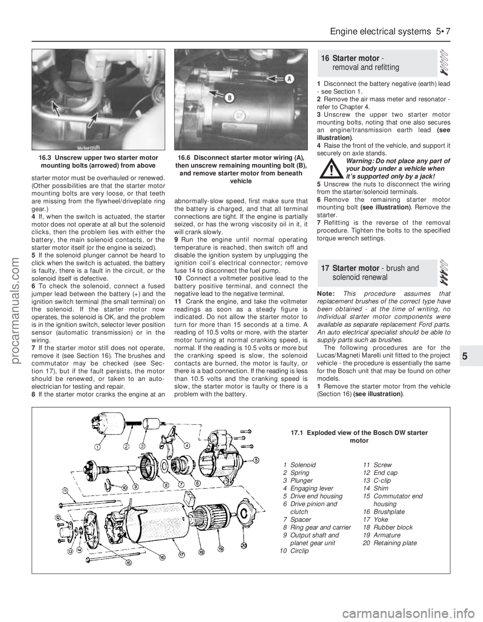
3Unscrew the upper two starter motor
mounting bolts, noting that one also secures
an engine/transmission earth lead (see
illustration).
4Raise the front of the vehicle, and support it
securely on axle stands.
Warning: Do not place any part of
your body under a vehicle when
it’s supported only by a jack!
5Unscrew the nuts to disconnect the wiring
from the starter/solenoid terminals.
6Remove the remaining starter motor
mounting bolt (see illustration). Remove the
starter.
7Refitting is the reverse of the removal
procedure. Tighten the bolts to the specified
torque wrench settings.
Note:This procedure assumes that
replacement brushes of the correct type have
been obtained - at the time of writing, no
individual starter motor components were
available as separate replacement Ford parts.
An auto electrical specialist should be able to
supply parts such as brushes.
The following procedures are for the
Lucas/Magneti Marelli unit fitted to the project
vehicle - the procedure is essentially the same
for the Bosch unit that may be found on other
models.
1Remove the starter motor from the vehicle
(Section 16) (see illustration).
17 Starter motor- brush and
solenoid renewal
16 Starter motor -
removal and refitting
Engine electrical systems 5•7
5
16.3 Unscrew upper two starter motor
mounting bolts (arrowed) from above16.6 Disconnect starter motor wiring (A),
then unscrew remaining mounting bolt (B),
and remove starter motor from beneath
vehicle
17.1 Exploded view of the Bosch DW starter
motor
1 Solenoid
2 Spring
3 Plunger
4 Engaging lever
5 Drive end housing
6 Drive pinion and
clutch
7 Spacer
8 Ring gear and carrier
9 Output shaft and
planet gear unit
10 Circlip11 Screw
12 End cap
13 C-clip
14 Shim
15 Commutator end
housing
16 Brushplate
17 Yoke
18 Rubber block
19 Armature
20 Retaining plate
procarmanuals.com
Page 194 of 279
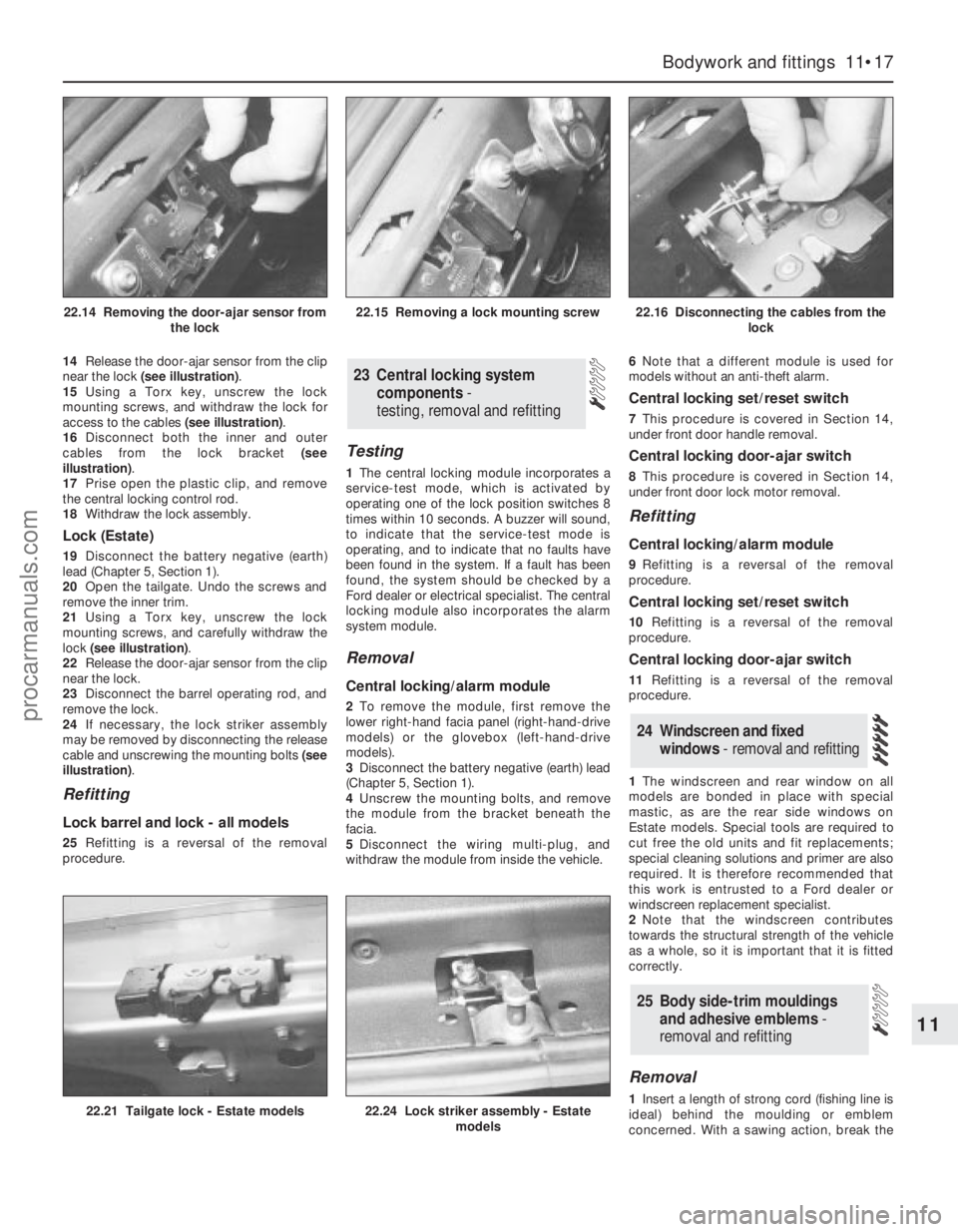
14Release the door-ajar sensor from the clip
near the lock (see illustration).
15Using a Torx key, unscrew the lock
mounting screws, and withdraw the lock for
access to the cables (see illustration).
16Disconnect both the inner and outer
cables from the lock bracket (see
illustration).
17Prise open the plastic clip, and remove
the central locking control rod.
18Withdraw the lock assembly.
Lock (Estate)
19Disconnect the battery negative (earth)
lead (Chapter 5, Section 1).
20Open the tailgate. Undo the screws and
remove the inner trim.
21Using a Torx key, unscrew the lock
mounting screws, and carefully withdraw the
lock (see illustration).
22Release the door-ajar sensor from the clip
near the lock.
23Disconnect the barrel operating rod, and
remove the lock.
24If necessary, the lock striker assembly
may be removed by disconnecting the release
cable and unscrewing the mounting bolts (see
illustration).
Refitting
Lock barrel and lock - all models
25Refitting is a reversal of the removal
procedure.
Testing
1The central locking module incorporates a
service-test mode, which is activated by
operating one of the lock position switches 8
times within 10 seconds. A buzzer will sound,
to indicate that the service-test mode is
operating, and to indicate that no faults have
been found in the system. If a fault has been
found, the system should be checked by a
Ford dealer or electrical specialist. The central
locking module also incorporates the alarm
system module.
Removal
Central locking/alarm module
2To remove the module, first remove the
lower right-hand facia panel (right-hand-drive
models) or the glovebox (left-hand-drive
models).
3Disconnect the battery negative (earth) lead
(Chapter 5, Section 1).
4Unscrew the mounting bolts, and remove
the module from the bracket beneath the
facia.
5Disconnect the wiring multi-plug, and
withdraw the module from inside the vehicle.6Note that a different module is used for
models without an anti-theft alarm.
Central locking set/reset switch
7This procedure is covered in Section 14,
under front door handle removal.
Central locking door-ajar switch
8This procedure is covered in Section 14,
under front door lock motor removal.
Refitting
Central locking/alarm module
9Refitting is a reversal of the removal
procedure.
Central locking set/reset switch
10Refitting is a reversal of the removal
procedure.
Central locking door-ajar switch
11Refitting is a reversal of the removal
procedure.
1The windscreen and rear window on all
models are bonded in place with special
mastic, as are the rear side windows on
Estate models. Special tools are required to
cut free the old units and fit replacements;
special cleaning solutions and primer are also
required. It is therefore recommended that
this work is entrusted to a Ford dealer or
windscreen replacement specialist.
2Note that the windscreen contributes
towards the structural strength of the vehicle
as a whole, so it is important that it is fitted
correctly.
Removal
1Insert a length of strong cord (fishing line is
ideal) behind the moulding or emblem
concerned. With a sawing action, break the
25 Body side-trim mouldings
and adhesive emblems -
removal and refitting
24 Windscreen and fixed
windows - removal and refitting
23 Central locking system
components-
testing, removal and refitting
Bodywork and fittings 11•17
11
22.21 Tailgate lock - Estate models22.24 Lock striker assembly - Estate
models
22.14 Removing the door-ajar sensor from
the lock22.15 Removing a lock mounting screw22.16 Disconnecting the cables from the
lock
procarmanuals.com
Page 266 of 279
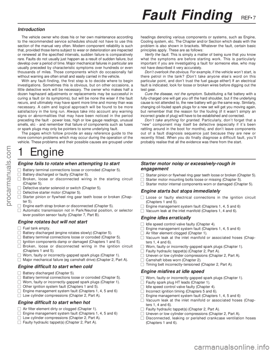
REF•7
Engine fails to rotate when attempting to start
m mBattery terminal connections loose or corroded (Chapter 5).
m mBattery discharged or faulty (Chapter 5).
m mBroken, loose or disconnected wiring in the starting circuit
(Chapter 5).
m mDefective starter solenoid or switch (Chapter 5).
m mDefective starter motor (Chapter 5).
m mStarter pinion or flywheel ring gear teeth loose or broken (Chap-
ter 5).
m mEngine earth strap broken or disconnected (Chapter 5).
m mAutomatic transmission not in Park/Neutral position, or selector
lever position sensor faulty (Chapter 7, Part B).
Engine rotates but will not start
m mFuel tank empty.
m mBattery discharged (engine rotates slowly) (Chapter 5).
m mBattery terminal connections loose or corroded (Chapter 5).
m mIgnition components damp or damaged (Chapters 1 and 5).
m mBroken, loose or disconnected wiring in the ignition circuit
(Chapters 1 and 5).
m mWorn, faulty or incorrectly-gapped spark plugs (Chapter 1).
m mMajor mechanical failure (eg camshaft drive) (Chapter 2, Part A).
Engine difficult to start when cold
m
mBattery discharged (Chapter 5).
m mBattery terminal connections loose or corroded (Chapter 5).
m mWorn, faulty or incorrectly-gapped spark plugs (Chapter 1).
m mOther ignition system fault (Chapters 1 and 5).
m mEngine management system fault (Chapters 1, 4, 5 and 6)
m mLow cylinder compressions (Chapter 2, Part A).
Engine difficult to start when hot
m
mAir filter element dirty or clogged (Chapter 1).
m mEngine management system fault (Chapters 1, 4, 5 and 6)
m mLow cylinder compressions (Chapter 2, Part A).
m mFaulty hydraulic tappet(s) (Chapter 2, Part A).
Starter motor noisy or excessively-rough in
engagement
m mStarter pinion or flywheel ring gear teeth loose or broken (Chapter 5).
m mStarter motor mounting bolts loose or missing (Chapter 5).
m mStarter motor internal components worn or damaged (Chapter 5).
Engine starts but stops immediately
m
mLoose or faulty electrical connections in the ignition circuit
(Chapters 1 and 5).
m mEngine management system fault (Chapters 1, 4, 5 and 6)
m mVacuum leak at the inlet manifold (Chapters 1, 4 and 6).
Engine idles erratically
m
mIdle speed control valve faulty (Chapter 4).
m mEngine management system fault (Chapters 1, 4, 5 and 6)
m mAir filter element clogged (Chapter 1).
m mVacuum leak at the inlet manifold or associated hoses (Chap-
ters 1, 4 and 6).
m mWorn, faulty or incorrectly-gapped spark plugs (Chapter 1).
m mFaulty hydraulic tappet(s) (Chapter 2, Part A).
m mUneven or low cylinder compressions (Chapter 2, Part A).
m mCamshaft lobes worn (Chapter 2).
m mTiming belt incorrectly-tensioned (Chapter 2, Part A).
Engine misfires at idle speed
m
mWorn, faulty or incorrectly-gapped spark plugs (Chapter 1).
m mFaulty spark plug HT leads (Chapter 1).
m mIdle speed control valve faulty (Chapter 4).
m mIncorrect ignition timing (Chapters 5 and 6).
m mEngine management system fault (Chapters 1, 4, 5 and 6)
m mVacuum leak at the inlet manifold or associated hoses (Chap-
ters 1, 4 and 6).
m mFaulty hydraulic tappet(s) (Chapter 2, Part A).
m mUneven or low cylinder compressions (Chapter 2, Part A).
m mDisconnected, leaking or perished crankcase ventilation hoses
(Chapters 1 and 6).
Fault Finding
The vehicle owner who does his or her own maintenance according
to the recommended service schedules should not have to use this
section of the manual very often. Modern component reliability is such
that, provided those items subject to wear or deterioration are inspected
or renewed at the specified intervals, sudden failure is comparatively
rare. Faults do not usually just happen as a result of sudden failure, but
develop over a period of time. Major mechanical failures in particular are
usually preceded by characteristic symptoms over hundreds or even
thousands of miles. Those components which do occasionally fail
without warning are often small and easily carried in the vehicle.
With any fault-finding, the first step is to decide where to begin
investigations. Sometimes this is obvious, but on other occasions, a
little detective work will be necessary. The owner who makes half a
dozen haphazard adjustments or replacements may be successful in
curing a fault (or its symptoms), but will be none the wiser if the fault
recurs, and ultimately may have spent more time and money than was
necessary. A calm and logical approach will be found to be more
satisfactory in the long run. Always take into account any warning
signs or abnormalities that may have been noticed in the period
preceding the fault - power loss, high or low gauge readings, unusual
smells, etc - and remember that failure of components such as fuses
or spark plugs may only be pointers to some underlying fault.
The pages which follow provide an easy reference guide to the
more common problems which may occur during the operation of the
vehicle. These problems and their possible causes are grouped underheadings denoting various components or systems, such as Engine,
Cooling system, etc. The Chapter and/or Section which deals with the
problem is also shown in brackets. Whatever the fault, certain basic
principles apply. These are as follows:
Verify the fault. This is simply a matter of being sure that you know
what the symptoms are before starting work. This is particularly
important if you are investigating a fault for someone else, who may
not have described it very accurately.
Don’t overlook the obvious. For example, if the vehicle won’t start, is
there petrol in the tank? (Don’t take anyone else’s word on this
particular point, and don’t trust the fuel gauge either!) If an electrical
fault is indicated, look for loose or broken wires before digging out the
test gear.
Cure the disease, not the symptom. Substituting a flat battery with a
fully-charged one will get you off the hard shoulder, but if the underlying
cause is not attended to, the new battery will go the same way. Similarly,
changing oil-fouled spark plugs for a new set will get you moving again,
but remember that the reason for the fouling (if it wasn’t simply an
incorrect grade of plug) will have to be established and corrected.
Don’t take anything for granted. Particularly, don’t forget that a
“new” component may itself be defective (especially if it’s been
rattling around in the boot for months), and don’t leave components
out of a fault diagnosis sequence just because they are new or
recently fitted. When you do finally diagnose a difficult fault, you’ll
probably realise that all the evidence was there from the start.
1 Engine
Introduction
procarmanuals.com