1993 FORD MONDEO oil viscosity
[x] Cancel search: oil viscosityPage 16 of 279
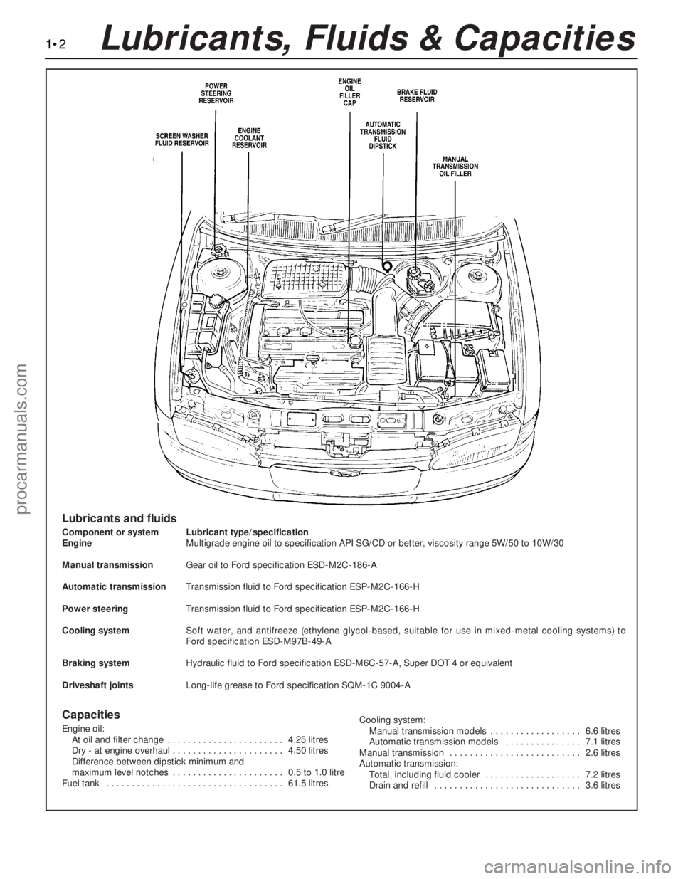
1•2Lubricants, Fluids & Capacities
Lubricants and fluids
Component or system Lubricant type/specification
EngineMultigrade engine oil to specification API SG/CD or better, viscosity range 5W/50 to 10W/30
Manual transmissionGear oil to Ford specification ESD-M2C-186-A
Automatic transmissionTransmission fluid to Ford specification ESP-M2C-166-H
Power steeringTransmission fluid to Ford specification ESP-M2C-166-H
Cooling systemSoft water, and antifreeze (ethylene glycol-based, suitable for use in mixed-metal cooling systems) to
Ford specification ESD-M97B-49-A
Braking systemHydraulic fluid to Ford specification ESD-M6C-57-A, Super DOT 4 or equivalent
Driveshaft jointsLong-life grease to Ford specification SQM-1C 9004-A
Capacities
Engine oil:
At oil and filter change . . . . . . . . . . . . . . . . . . . . . . . 4.25 litres
Dry - at engine overhaul . . . . . . . . . . . . . . . . . . . . . . 4.50 litres
Difference between dipstick minimum and
maximum level notches . . . . . . . . . . . . . . . . . . . . . . 0.5 to 1.0 litre
Fuel tank . . . . . . . . . . . . . . . . . . . . . . . . . . . . . . . . . . . 61.5 litresCooling system:
Manual transmission models . . . . . . . . . . . . . . . . . . 6.6 litres
Automatic transmission models . . . . . . . . . . . . . . . 7.1 litres
Manual transmission . . . . . . . . . . . . . . . . . . . . . . . . . . 2.6 litres
Automatic transmission:
Total, including fluid cooler . . . . . . . . . . . . . . . . . . . 7.2 litres
Drain and refill . . . . . . . . . . . . . . . . . . . . . . . . . . . . . 3.6 litres
procarmanuals.com
Page 45 of 279
The cylinder head is provided with two oil
galleries, one on the inlet side and one on the
exhaust, to ensure constant oil supply to the
camshaft bearings and hydraulic tappets. A
retaining valve (inserted into the cylinder
head’s top surface, in the middle, on the inlet
side) prevents these galleries from being
drained when the engine is switched off. The
valve incorporates a ventilation hole in its
upper end, to allow air bubbles to escape
from the system when the engine is restarted.
While the crankshaft and camshaft
bearings and the hydraulic tappets receive a
pressurised supply, the camshaft lobes and
valves are lubricated by splash, as are all
other engine components.
Valve clearances - general
It is necessary for a clearance to exist
between the tip of each valve stem and the
valve operating mechanism, to allow for the
expansion of the various components as the
engine reaches normal operating
temperature.
On most older engine designs, this meant
that the valve clearances (also known as
“tappet” clearances) had to be checked and
adjusted regularly. If the clearances were
allowed to be too slack, the engine would be
very noisy, its power output would suffer, and
its fuel consumption would increase. If the
clearances were allowed to be too tight, the
engine’s power output would be reduced,
and the valves and their seats could be
severely damaged.
The engines covered in this manual,
however, employ hydraulic tappets which use
the lubricating system’s oil pressure
automatically to take up the clearance
between each camshaft lobe and its
respective valve stem. Therefore, there is no
need for regular checking and adjustment of
the valve clearances, but it is essential that
onlygood-quality oil of the recommended
viscosity and specification is used in the
engine, and that this oil is always changed at
the recommended intervals. If this advice is
not followed, the oilways and tappets may
become clogged with particles of dirt, or
deposits of burnt (inferior) engine oil, so that
the system cannot work properly; ultimately,
one or more of the tappets may fail, and
expensive repairs may be required.
On starting the engine from cold, there will
be a slight delay while full oil pressure builds
up in all parts of the engine, especially in the
tappets; the valve components, therefore,
may well “rattle” for about 10 seconds or so,
and then quieten. This is a normal state of
affairs, and is nothing to worry about,
provided that all tappets quieten quickly and
stay quiet.
After the vehicle has been standing for
several days, the valve components may
“rattle” for longer than usual, as nearly all the
oil will have drained away from the engine’s
top end components and bearing surfaces.
While this is only to be expected, care mustbe taken not to damage the engine under
these circumstances - avoid high speed
running until all the tappets are refilled with oil
and operating normally. With the vehicle
stationary, hold the engine at no more than a
fast idle speed (maximum 2000 to 2500 rpm)
for 10 to 15 seconds, or until the noise
ceases. Do not run the engine at more than
3000 rpm until the tappets are fully recharged
with oil and the noise has ceased.
If the valve components are thought to be
noisy, or if a light rattle persists from the top
end after the engine has warmed up to
normal operating temperature, take the
vehicle to a Ford dealer for expert advice.
Depending on the mileage covered and the
usage to which each vehicle has been put,
some vehicles may be noisier than others;
only a good mechanic experienced in these
engines can tell if the noise level is typical for
the vehicle’s mileage, or if a genuine fault
exists. If any tappet’s operation is faulty, it
must be renewed (Section 13).
The following major repair operations can
be accomplished without removing the
engine from the vehicle. However, owners
should note that any operation involving the
removal of the sump requires careful
forethought, depending on the level of skill
and the tools and facilities available; refer to
the relevant text for details.
(a) Compression pressure - testing.
(b) Cylinder head cover - removal and
refitting.
(c) Timing belt covers - removal and refitting.
(d) Timing belt - renewal.
(e) Timing belt tensioner and toothed pulleys
- removal and refitting.
(f) Camshaft oil seals - renewal.
(g) Camshafts and hydraulic tappets -
removal and refitting.
(h) Cylinder head - removal, overhaul and
refitting.
(i) Cylinder head and pistons -
decarbonising.
(j) Sump - removal and refitting.
(k) Crankshaft oil seals - renewal.
(l) Oil pump - removal and refitting.
(m) Piston/connecting rod assemblies -
removal and refitting (but see note below).
(n) Flywheel/driveplate - removal and
refitting.
(o) Engine/transmission mountings - removal
and refitting.
Clean the engine compartment and the
exterior of the engine with some type of
degreaser before any work is done. It will
make the job easier, and will help to keep dirt
out of the internal areas of the engine.
Depending on the components involved, it
may be helpful to remove the bonnet, to
improve access to the engine as repairs are
performed (refer to Chapter 11 if necessary).Cover the wings to prevent damage to the
paint; special covers are available, but an old
bedspread or blanket will also work.
If vacuum, exhaust, oil or coolant leaks
develop, indicating a need for component/
gasket or seal replacement, the repairs can
generally be made with the engine in the
vehicle. The intake and exhaust manifold
gaskets, sump gasket, crankshaft oil seals
and cylinder head gasket are all accessible
with the engine in place.
Exterior components such as the intake
and exhaust manifolds, the sump, the oil
pump, the water pump, the starter motor, the
alternator and the fuel system components
can be removed for repair with the engine in
place.
Since the cylinder head can be removed
without lifting out the engine, camshaft and
valve component servicing can also be
accomplished with the engine in the vehicle,
as can renewal of the timing belt and toothed
pulleys.
In extreme cases caused by a lack of
necessary equipment, repair or renewal of
piston rings, pistons, connecting rods and
big-end bearings is possible with the engine
in the vehicle. However, this practice is not
recommended, because of the cleaning and
preparation work that must be done to the
components involved, and because of the
amount of preliminary dismantling work
required - these operations are therefore
covered in Part B of this Chapter.
1When engine performance is down, or if
misfiring occurs which cannot be attributed to
the ignition or fuel systems, a compression
test can provide diagnostic clues as to the
engine’s condition. If the test is performed
regularly, it can give warning of trouble before
any other symptoms become apparent.
2The engine must be fully warmed-up to
normal operating temperature, the oil level
must be correct, the battery must be fully
charged, and the spark plugs must be
removed. The aid of an assistant will be
required also.
3Disable the ignition system by unplugging
the ignition coil’s electrical connector, and
remove fuse 14 to disconnect the fuel pump.
4Fit a compression tester to the No 1
cylinder spark plug hole - the type of tester
which screws into the plug thread is to be
preferred.
5Have the assistant hold the throttle wide
open and crank the engine on the starter
motor; after one or two revolutions, the
compression pressure should build up to a
maximum figure, and then stabilise. Record
the highest reading obtained.
6Repeat the test on the remaining cylinders,
recording the pressure developed in each.
7At the time of writing, no compression
3 Compression test -
description and interpretation
2 Repair operations possible with
the engine in the vehicle
In-car engine repair procedures 2A•5
2A
procarmanuals.com
Page 55 of 279
wear (scoring, pitting etc) and for ovality, and
renew if necessary.
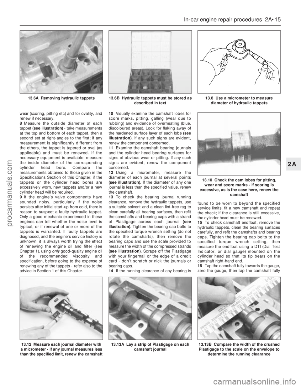
8Measure the outside diameter of each
tappet (see illustration)- take measurements
at the top and bottom of each tappet, then a
second set at right-angles to the first; if any
measurement is significantly different from
the others, the tappet is tapered or oval (as
applicable) and must be renewed. If the
necessary equipment is available, measure
the inside diameter of the corresponding
cylinder head bore. Compare the
measurements obtained to those given in the
Specifications Section of this Chapter; if the
tappets or the cylinder head bores are
excessively worn, new tappets and/or a new
cylinder head will be required.
9If the engine’s valve components have
sounded noisy, particularly if the noise
persists after initial start-up from cold, there is
reason to suspect a faulty hydraulic tappet.
Only a good mechanic experienced in these
engines can tell whether the noise level is
typical, or if renewal of one or more of the
tappets is warranted. If faulty tappets are
diagnosed, and the engine’s service history is
unknown, it is always worth trying the effect
of renewing the engine oil and filter (see
Chapter 1), using onlygood-quality engine oil
of the recommended viscosity and
specification, before going to the expense of
renewing any of the tappets - refer also to the
advice in Section 1 of this Chapter.10Visually examine the camshaft lobes for
score marks, pitting, galling (wear due to
rubbing) and evidence of overheating (blue,
discoloured areas). Look for flaking away of
the hardened surface layer of each lobe (see
illustration). If any such signs are evident,
renew the component concerned.
11Examine the camshaft bearing journals
and the cylinder head bearing surfaces for
signs of obvious wear or pitting. If any such
signs are evident, renew the component
concerned.
12Using a micrometer, measure the
diameter of each journal at several points
(see illustration). If the diameter of any one
journal is less than the specified value, renew
the camshaft.
13To check the bearing journal running
clearance, remove the hydraulic tappets, use
a suitable solvent and a clean lint-free rag to
clean carefully all bearing surfaces, then refit
the camshafts and bearing caps with a strand
of Plastigage across each journal (see
illustration). Tighten the bearing cap bolts to
the specified torque wrench setting (do not
rotate the camshafts), then remove the
bearing caps and use the scale provided to
measure the width of the compressed strands
(see illustration). Scrape off the Plastigage
with your fingernail or the edge of a credit
card - don’t scratch or nick the journals or
bearing caps.
14If the running clearance of any bearing isfound to be worn to beyond the specified
service limits, fit a new camshaft and repeat
the check; if the clearance is still excessive,
the cylinder head must be renewed.
15To check camshaft endfloat, remove the
hydraulic tappets, clean the bearing surfaces
carefully, and refit the camshafts and bearing
caps. Tighten the bearing cap bolts to the
specified torque wrench setting, then
measure the endfloat using a DTI (Dial Test
Indicator, or dial gauge) mounted on the
cylinder head so that its tip bears on the
camshaft right-hand end.
16Tap the camshaft fully towards the gauge,
zero the gauge, then tap the camshaft fully
In-car engine repair procedures 2A•15
2A
13.12 Measure each journal diameter with
a micrometer - if any journal measures less
than the specified limit, renew the camshaft13.13A Lay a strip of Plastigage on each
camshaft journal13.13B Compare the width of the crushed
Plastigage to the scale on the envelope to
determine the running clearance
13.6A Removing hydraulic tappets13.6B Hydraulic tappets must be stored as
described in text13.8 Use a micrometer to measure
diameter of hydraulic tappets
13.10 Check the cam lobes for pitting,
wear and score marks - if scoring is
excessive, as is the case here, renew the
camshaft
procarmanuals.com
Page 117 of 279
starter motor must be overhauled or renewed.
(Other possibilities are that the starter motor
mounting bolts are very loose, or that teeth
are missing from the flywheel/driveplate ring
gear.)
4If, when the switch is actuated, the starter
motor does not operate at all but the solenoid
clicks, then the problem lies with either the
battery, the main solenoid contacts, or the
starter motor itself (or the engine is seized).
5If the solenoid plunger cannot be heard to
click when the switch is actuated, the battery
is faulty, there is a fault in the circuit, or the
solenoid itself is defective.
6To check the solenoid, connect a fused
jumper lead between the battery (+) and the
ignition switch terminal (the small terminal) on
the solenoid. If the starter motor now
operates, the solenoid is OK, and the problem
is in the ignition switch, selector lever position
sensor (automatic transmission) or in the
wiring.
7If the starter motor still does not operate,
remove it (see Section 16). The brushes and
commutator may be checked (see Sec-
tion 17), but if the fault persists, the motor
should be renewed, or taken to an auto-
electrician for testing and repair.
8If the starter motor cranks the engine at anabnormally-slow speed, first make sure that
the battery is charged, and that all terminal
connections are tight. If the engine is partially
seized, or has the wrong viscosity oil in it, it
will crank slowly.
9Run the engine until normal operating
temperature is reached, then switch off and
disable the ignition system by unplugging the
ignition coil’s electrical connector; remove
fuse 14 to disconnect the fuel pump.
10Connect a voltmeter positive lead to the
battery positive terminal, and connect the
negative lead to the negative terminal.
11Crank the engine, and take the voltmeter
readings as soon as a steady figure is
indicated. Do not allow the starter motor to
turn for more than 15 seconds at a time. A
reading of 10.5 volts or more, with the starter
motor turning at normal cranking speed, is
normal. If the reading is 10.5 volts or more but
the cranking speed is slow, the solenoid
contacts are burned, the motor is faulty, or
there is a bad connection. If the reading is less
than 10.5 volts and the cranking speed is
slow, the starter motor is faulty or there is a
problem with the battery.1Disconnect the battery negative (earth) lead
- see Section 1.
2Remove the air mass meter and resonator -
refer to Chapter 4.
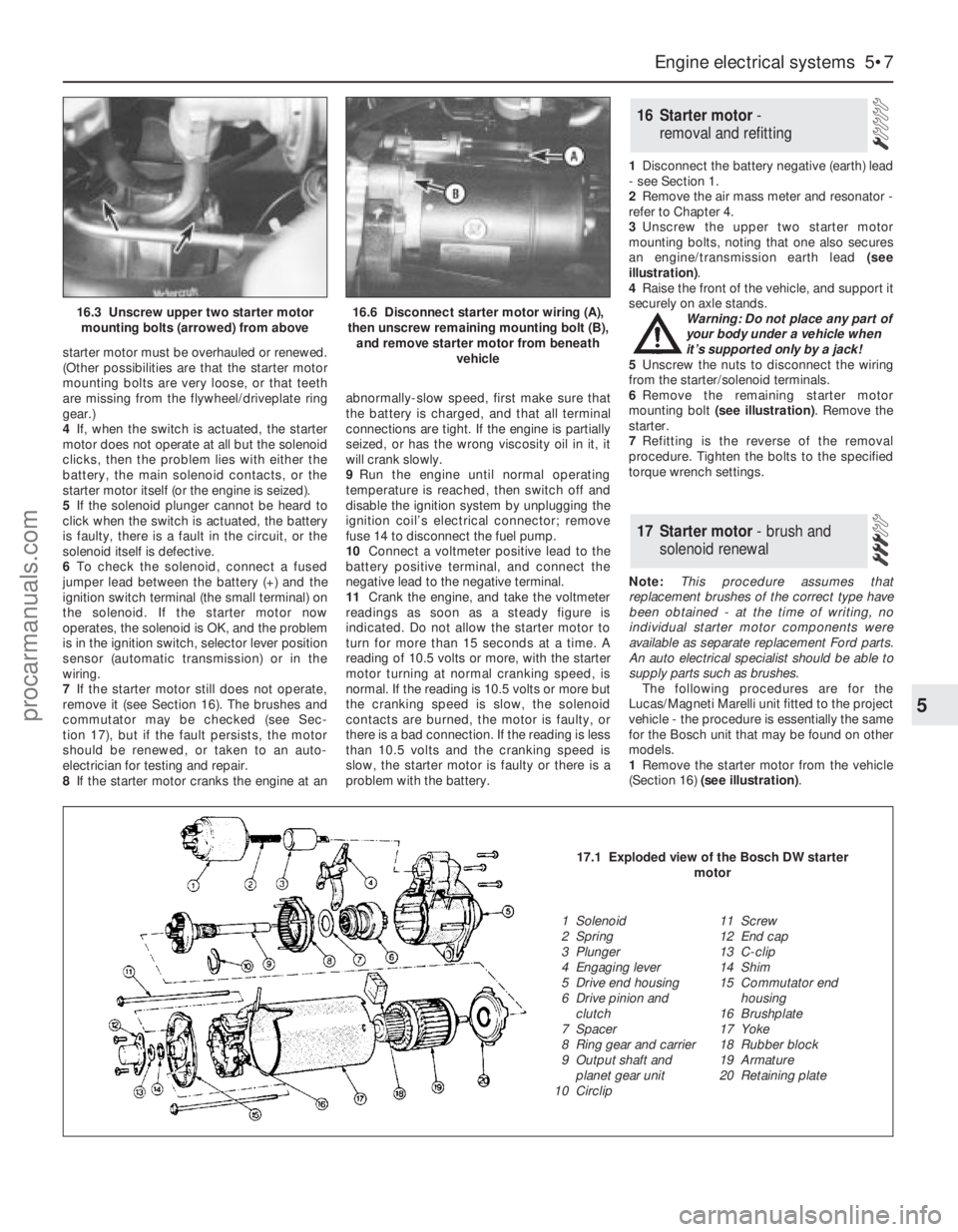
3Unscrew the upper two starter motor
mounting bolts, noting that one also secures
an engine/transmission earth lead (see
illustration).
4Raise the front of the vehicle, and support it
securely on axle stands.
Warning: Do not place any part of
your body under a vehicle when
it’s supported only by a jack!
5Unscrew the nuts to disconnect the wiring
from the starter/solenoid terminals.
6Remove the remaining starter motor
mounting bolt (see illustration). Remove the
starter.
7Refitting is the reverse of the removal
procedure. Tighten the bolts to the specified
torque wrench settings.
Note:This procedure assumes that
replacement brushes of the correct type have
been obtained - at the time of writing, no
individual starter motor components were
available as separate replacement Ford parts.
An auto electrical specialist should be able to
supply parts such as brushes.
The following procedures are for the
Lucas/Magneti Marelli unit fitted to the project
vehicle - the procedure is essentially the same
for the Bosch unit that may be found on other
models.
1Remove the starter motor from the vehicle
(Section 16) (see illustration).
17 Starter motor- brush and
solenoid renewal
16 Starter motor -
removal and refitting
Engine electrical systems 5•7
5
16.3 Unscrew upper two starter motor
mounting bolts (arrowed) from above16.6 Disconnect starter motor wiring (A),
then unscrew remaining mounting bolt (B),
and remove starter motor from beneath
vehicle
17.1 Exploded view of the Bosch DW starter
motor
1 Solenoid
2 Spring
3 Plunger
4 Engaging lever
5 Drive end housing
6 Drive pinion and
clutch
7 Spacer
8 Ring gear and carrier
9 Output shaft and
planet gear unit
10 Circlip11 Screw
12 End cap
13 C-clip
14 Shim
15 Commutator end
housing
16 Brushplate
17 Yoke
18 Rubber block
19 Armature
20 Retaining plate
procarmanuals.com
Page 275 of 279
REF•16Glossary of Technical Terms
RotorIn a distributor, the rotating device
inside the cap that connects the centre
electrode and the outer terminals as it turns,
distributing the high voltage from the coil
secondary winding to the proper spark plug.
Also, that part of an alternator which rotates
inside the stator. Also, the rotating assembly
of a turbocharger, including the compressor
wheel, shaft and turbine wheel.
RunoutThe amount of wobble (in-and-out
movement) of a gear or wheel as it’s rotated.
The amount a shaft rotates “out-of-true.” The
out-of-round condition of a rotating part.
SSealantA liquid or paste used to prevent
leakage at a joint. Sometimes used in
conjunction with a gasket.
Sealed beam lampAn older headlight design
which integrates the reflector, lens and
filaments into a hermetically-sealed one-piece
unit. When a filament burns out or the lens
cracks, the entire unit is simply replaced.
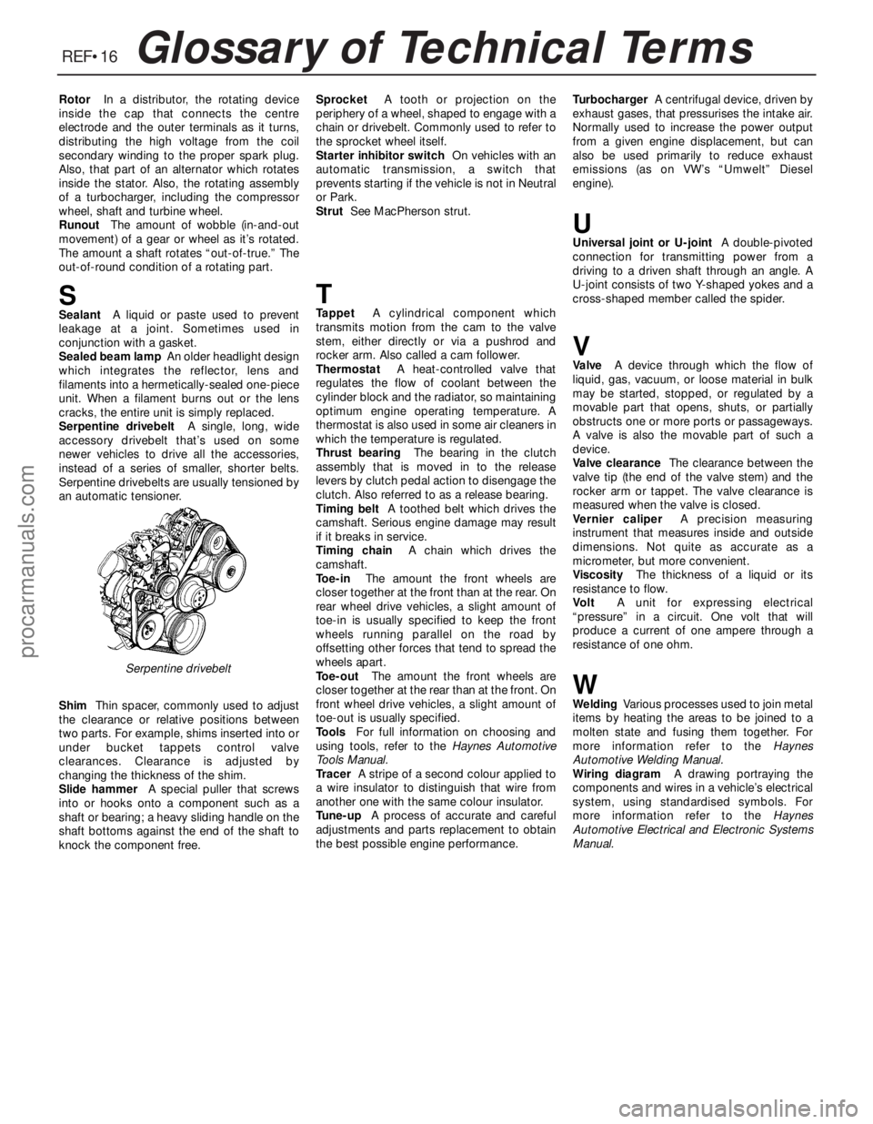
Serpentine drivebeltA single, long, wide
accessory drivebelt that’s used on some
newer vehicles to drive all the accessories,
instead of a series of smaller, shorter belts.
Serpentine drivebelts are usually tensioned by
an automatic tensioner.
ShimThin spacer, commonly used to adjust
the clearance or relative positions between
two parts. For example, shims inserted into or
under bucket tappets control valve
clearances. Clearance is adjusted by
changing the thickness of the shim.
Slide hammerA special puller that screws
into or hooks onto a component such as a
shaft or bearing; a heavy sliding handle on the
shaft bottoms against the end of the shaft to
knock the component free.SprocketA tooth or projection on the
periphery of a wheel, shaped to engage with a
chain or drivebelt. Commonly used to refer to
the sprocket wheel itself.
Starter inhibitor switchOn vehicles with an
automatic transmission, a switch that
prevents starting if the vehicle is not in Neutral
or Park.
StrutSee MacPherson strut.
TTappetA cylindrical component which
transmits motion from the cam to the valve
stem, either directly or via a pushrod and
rocker arm. Also called a cam follower.
ThermostatA heat-controlled valve that
regulates the flow of coolant between the
cylinder block and the radiator, so maintaining
optimum engine operating temperature. A
thermostat is also used in some air cleaners in
which the temperature is regulated.
Thrust bearingThe bearing in the clutch
assembly that is moved in to the release
levers by clutch pedal action to disengage the
clutch. Also referred to as a release bearing.
Timing beltA toothed belt which drives the
camshaft. Serious engine damage may result
if it breaks in service.
Timing chainA chain which drives the
camshaft.
Toe-inThe amount the front wheels are
closer together at the front than at the rear. On
rear wheel drive vehicles, a slight amount of
toe-in is usually specified to keep the front
wheels running parallel on the road by
offsetting other forces that tend to spread the
wheels apart.
Toe-outThe amount the front wheels are
closer together at the rear than at the front. On
front wheel drive vehicles, a slight amount of
toe-out is usually specified.
ToolsFor full information on choosing and
using tools, refer to the Haynes Automotive
Tools Manual.
TracerA stripe of a second colour applied to
a wire insulator to distinguish that wire from
another one with the same colour insulator.
Tune-upA process of accurate and careful
adjustments and parts replacement to obtain
the best possible engine performance.TurbochargerA centrifugal device, driven by
exhaust gases, that pressurises the intake air.
Normally used to increase the power output
from a given engine displacement, but can
also be used primarily to reduce exhaust
emissions (as on VW’s “Umwelt” Diesel
engine).
UUniversal joint or U-jointA double-pivoted
connection for transmitting power from a
driving to a driven shaft through an angle. A
U-joint consists of two Y-shaped yokes and a
cross-shaped member called the spider.
VValveA device through which the flow of
liquid, gas, vacuum, or loose material in bulk
may be started, stopped, or regulated by a
movable part that opens, shuts, or partially
obstructs one or more ports or passageways.
A valve is also the movable part of such a
device.
Valve clearanceThe clearance between the
valve tip (the end of the valve stem) and the
rocker arm or tappet. The valve clearance is
measured when the valve is closed.
Vernier caliperA precision measuring
instrument that measures inside and outside
dimensions. Not quite as accurate as a
micrometer, but more convenient.
ViscosityThe thickness of a liquid or its
resistance to flow.
VoltA unit for expressing electrical
“pressure” in a circuit. One volt that will
produce a current of one ampere through a
resistance of one ohm.
WWeldingVarious processes used to join metal
items by heating the areas to be joined to a
molten state and fusing them together. For
more information refer to the Haynes
Automotive Welding Manual.
Wiring diagramA drawing portraying the
components and wires in a vehicle’s electrical
system, using standardised symbols. For
more information refer to the Haynes
Automotive Electrical and Electronic Systems
Manual.
Serpentine drivebelt
procarmanuals.com