1993 FORD MONDEO service indicator
[x] Cancel search: service indicatorPage 23 of 279
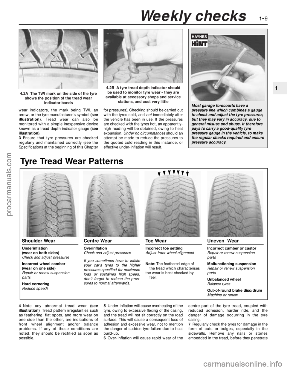
wear indicators, the mark being TWI, an
arrow, or the tyre manufacturer’s symbol (see
illustration). Tread wear can also be
monitored with a simple inexpensive device
known as a tread depth indicator gauge (see
illustration).
3Ensure that tyre pressures are checked
regularly and maintained correctly (see the
Specifications at the beginning of this Chapterfor pressures). Checking should be carried out
with the tyres cold, and notimmediately after
the vehicle has been in use. If the pressures
are checked with the tyres hot, an apparently-
high reading will be obtained, owing to heat
expansion. Under no circumstancesshould an
attempt be made to reduce the pressures to
the quoted cold reading in this instance, or
effective under-inflation will result.
1•9
1
Tyre Tread Wear Patterns
Shoulder Wear
Underinflation
(wear on both sides)
Check and adjust pressures
Incorrect wheel camber
(wear on one side)
Repair or renew suspension
parts
Hard cornering
Reduce speed!
Centre Wear
Overinflation
Check and adjust pressures
If you sometimes have to inflate
your car’s tyres to the higher
pressures specified for maximum
load or sustained high speed,
don’t forget to reduce the pres-
sures to normal afterwards.
Toe Wear
Incorrect toe setting
Adjust front wheel alignment
Note: The feathered edge of
the tread which characterises
toe wear is best checked by
feel.
Uneven Wear
Incorrect camber or castor
Repair or renew suspension
parts
Malfunctioning suspension
Repair or renew suspension
parts
Unbalanced wheel
Balance tyres
Out-of-round brake disc/drum
Machine or renew
4.2A The TWI mark on the side of the tyre
shows the position of the tread wear
indicator bands
4.2B A tyre tread depth indicator should
be used to monitor tyre wear - they are
available at accessory shops and service
stations, and cost very little
Weekly checks
Most garage forecourts have a
pressure line which combines a gauge
to check and adjust the tyre pressures,
but they may vary in accuracy, due to
general misuse and abuse. It therefore
pays to carry a good-quality tyre
pressure gauge in the vehicle, to make
the regular checks required and ensure
pressure accuracy.
4Note any abnormal tread wear (see
illustration). Tread pattern irregularities such
as feathering, flat spots, and more wear on
one side than the other, are indications of
front wheel alignment and/or balance
problems. If any of these conditions are
noted, they should be rectified as soon as
possible.5Under-inflation will cause overheating of the
tyre, owing to excessive flexing of the casing,
and the tread will not sit correctly on the road
surface. This will cause a consequent loss of
adhesion and excessive wear, not to mention
the danger of sudden tyre failure due to heat
build-up.
6Over-inflation will cause rapid wear of thecentre part of the tyre tread, coupled with
reduced adhesion, harder ride, and the
danger of damage occurring in the tyre
casing.
7Regularly check the tyres for damage in the
form of cuts or bulges, especially in the
sidewalls. Remove any nails or stones
embedded in the tread, before they penetrate
procarmanuals.com
Page 55 of 279
wear (scoring, pitting etc) and for ovality, and
renew if necessary.
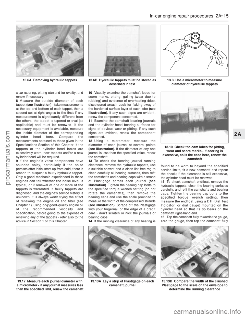
8Measure the outside diameter of each
tappet (see illustration)- take measurements
at the top and bottom of each tappet, then a
second set at right-angles to the first; if any
measurement is significantly different from
the others, the tappet is tapered or oval (as
applicable) and must be renewed. If the
necessary equipment is available, measure
the inside diameter of the corresponding
cylinder head bore. Compare the
measurements obtained to those given in the
Specifications Section of this Chapter; if the
tappets or the cylinder head bores are
excessively worn, new tappets and/or a new
cylinder head will be required.
9If the engine’s valve components have
sounded noisy, particularly if the noise
persists after initial start-up from cold, there is
reason to suspect a faulty hydraulic tappet.
Only a good mechanic experienced in these
engines can tell whether the noise level is
typical, or if renewal of one or more of the
tappets is warranted. If faulty tappets are
diagnosed, and the engine’s service history is
unknown, it is always worth trying the effect
of renewing the engine oil and filter (see
Chapter 1), using onlygood-quality engine oil
of the recommended viscosity and
specification, before going to the expense of
renewing any of the tappets - refer also to the
advice in Section 1 of this Chapter.10Visually examine the camshaft lobes for
score marks, pitting, galling (wear due to
rubbing) and evidence of overheating (blue,
discoloured areas). Look for flaking away of
the hardened surface layer of each lobe (see
illustration). If any such signs are evident,
renew the component concerned.
11Examine the camshaft bearing journals
and the cylinder head bearing surfaces for
signs of obvious wear or pitting. If any such
signs are evident, renew the component
concerned.
12Using a micrometer, measure the
diameter of each journal at several points
(see illustration). If the diameter of any one
journal is less than the specified value, renew
the camshaft.
13To check the bearing journal running
clearance, remove the hydraulic tappets, use
a suitable solvent and a clean lint-free rag to
clean carefully all bearing surfaces, then refit
the camshafts and bearing caps with a strand
of Plastigage across each journal (see
illustration). Tighten the bearing cap bolts to
the specified torque wrench setting (do not
rotate the camshafts), then remove the
bearing caps and use the scale provided to
measure the width of the compressed strands
(see illustration). Scrape off the Plastigage
with your fingernail or the edge of a credit
card - don’t scratch or nick the journals or
bearing caps.
14If the running clearance of any bearing isfound to be worn to beyond the specified
service limits, fit a new camshaft and repeat
the check; if the clearance is still excessive,
the cylinder head must be renewed.
15To check camshaft endfloat, remove the
hydraulic tappets, clean the bearing surfaces
carefully, and refit the camshafts and bearing
caps. Tighten the bearing cap bolts to the
specified torque wrench setting, then
measure the endfloat using a DTI (Dial Test
Indicator, or dial gauge) mounted on the
cylinder head so that its tip bears on the
camshaft right-hand end.
16Tap the camshaft fully towards the gauge,
zero the gauge, then tap the camshaft fully
In-car engine repair procedures 2A•15
2A
13.12 Measure each journal diameter with
a micrometer - if any journal measures less
than the specified limit, renew the camshaft13.13A Lay a strip of Plastigage on each
camshaft journal13.13B Compare the width of the crushed
Plastigage to the scale on the envelope to
determine the running clearance
13.6A Removing hydraulic tappets13.6B Hydraulic tappets must be stored as
described in text13.8 Use a micrometer to measure
diameter of hydraulic tappets
13.10 Check the cam lobes for pitting,
wear and score marks - if scoring is
excessive, as is the case here, renew the
camshaft
procarmanuals.com
Page 100 of 279
This Chapter is concerned with those
features of the engine management system
that supply clean fuel and air to the engine,
meter it in the required proportions, and
dispose of the results. Since the emission
control sub-systems modify the functions of
both the fuel and exhaust sub-systems, all of
which are integral parts of the whole engine
management system, there are many cross-
references to Chapters 5 and 6. Information
on the electronic control system, its fault
diagnosis, sensors and actuators, is given in
Chapter 6.
The air intake system consists of several
plastics components designed to eliminate
induction roar as much as possible. The air
intake tube (opening behind the direction
indicator/headlight assembly) is connected,
via small and large resonators located under
the front left-hand wing, to the air cleaner
assembly in the engine compartment. Once it
has passed through the filter element and the
air mass meter, the air enters the plenum
chamber mounted above the throttle housing
and inlet manifold; the resonator mounted in
the engine compartment further reduces noise
levels.
The fuel system consists of a plastic tank
(mounted under the body, beneath the rear
seats), combined metal and plastic fuel hoses,
an electric fuel pump mounted in the fuel tank,
and an electronic fuel injection system.
The exhaust system consists of an exhaust
manifold, the front downpipe and catalytic
converter and, on production-fit systems, a
rear section incorporating two or three
silencers and the tailpipe assembly. The
service replacement exhaust system consists
of three or four sections: the front
downpipe/catalytic converter, the
intermediate pipe and front silencer, and the
tailpipe and rear silencer. On some versions,
the tailpipe is in two pieces, with two rear
silencers. The system is suspended
throughout its entire length by rubber
mountings.
Extreme caution should be exercised when
dealing with either the fuel or exhaust
systems. Fuel is a primary element for
combustion. Be very careful! The exhaust
system is an area for exercising caution, as it
operates at very high temperatures. Serious
burns can result from even momentary
contact with any part of the exhaust system,
and the fire risk is ever-present. The catalytic
converter in particular runs at very high
temperatures - refer to the information in
Chapter 6.
Warning: Many of the procedures
in this Chapter require the
removal of fuel lines and
connections, which may result in
some fuel spillage. Petrol is extremely
flammable, so take extra precautionswhen you work on any part of the fuel
system. Don’t smoke, or allow open flames
or bare light bulbs, near the work area.
Don’t work in a garage where a natural
gas-type appliance (such as a water
heater or clothes dryer) with a pilot light is
present. If you spill any fuel on your skin,
rinse it off immediately with soap and
water. When you perform any kind of work
on the fuel system, wear safety glasses,
and have a Class B type fire extinguisher
on hand. Before carrying out any operation
on the fuel system, refer also to the
precautions given in “Safety first!” at the
beginning of this manual, and follow them
implicitly. Petrol is a highly-dangerous and
volatile liquid, and the precautions
necessary when handling it cannot be
overstressed.
Warning: The fuel system will
remain pressurised for long
periods of time after the engine is
switched off - this pressure must
be released before any part of the system
is disturbed. Petrol is extremely
flammable, so take extra precautions
when you work on any part of the fuel
system. Don’t smoke, or allow open flames
or bare light bulbs, near the work area.
Don’t work in a garage where a natural
gas-type appliance (such as a water
heater or clothes dryer) with a pilot light is
present. If you spill any fuel on your skin,
rinse it off immediately with soap and
water. When you perform any kind of work
on the fuel system, wear safety glasses,
and have a Class B type fire extinguisher
on hand.
1The fuel system referred to in this Chapter
is defined as the fuel tank and tank-mounted
fuel pump/fuel gauge sender unit, the fuel
filter, the fuel injectors and the pressure
regulator in the injector rail, and the metal
pipes and flexible hoses of the fuel lines
between these components. All these contain
fuel, which will be under pressure while the
engine is running and/or while the ignition is
switched on.
2The pressure will remain for some time after
the ignition has been switched off, and must
be relieved before any of these components is
disturbed for servicing work.
3The simplest method is simply to
disconnect the fuel pump’s electrical supply
while the engine is running - either by
removing the fuel pump fuse (number 14), or
by lifting the red button on the fuel cut-off
switch (see Section 13) - and to allow the
engine to idle until it dies through lack of fuel
pressure. Turn the engine over once or twice
on the starter to ensure that all pressure is
released, then switch off the ignition; do not
forget to refit the fuse (or depress the redbutton, as appropriate) when work is
complete.
4The Ford method of depressurisation is to
use service tool 29-033 fitted to the fuel rail
pressure test/release fitting - a Schrader-type
valve with a blue plastic cap, located on the
union of the fuel feed line and the fuel rail - to
release the pressure, using a suitable
container and wads of rag to catch the spilt
fuel. Do notsimply depress the valve core to
release fuel pressure - droplets of fuel will
spray out, with a consequent risk of fire, and
of personal injury through fuel getting into
your eyes.
Warning: Either procedure will
merely relieve the increased
pressure necessary for the
engine to run. Remember that
fuel will still be present in the system
components, and take precautions
accordingly before disconnecting any of
them.
5Note that, once the fuel system has been
depressurised and drained (even partially), it
will take significantly longer to restart the
engine - perhaps several seconds of cranking
- before the system is refilled and pressure
restored.
Warning: The fuel system
pressure must be released before
any part of the system is
disturbed - see Section 2. Petrol
is extremely flammable, so take extra
precautions when you work on any part of
the fuel system. Don’t smoke, or allow
open flames or bare light bulbs, near the
work area. Don’t work in a garage where a
natural gas-type appliance (such as a
water heater or clothes dryer) with a pilot
light is present. If you spill any fuel on your
skin, rinse it off immediately with soap and
water. When you perform any kind of work
on the fuel system, wear safety glasses,
and have a Class B type fire extinguisher
on hand.
Disconnecting and connecting
quick-release couplings
1Quick-release couplings are employed at all
unions in the fuel feed and return lines.
2Before disconnecting any fuel system
component, relieve the residual pressure in
the system (see Section 2), and equalise tank
pressure by removing the fuel filler cap.
Warning: This procedure will
merely relieve the increased
pressure necessary for the
engine to run - remember that
fuel will still be present in the system
components, and take precautions
accordingly before disconnecting any of
them.
3 Fuel lines and fittings-
general information
2 Fuel system - depressurisation
1 General information and
precautions
4•2 Fuel and exhaust systems
procarmanuals.com
Page 140 of 279
back again, as an assistant depresses the
accelerator pedal. If the valve shows any sign
of stiffness, sticking or otherwise-inhibited
movement (and the accelerator cable is
known from the previous check to be in good
condition), spray the throttle linkage with
penetrating lubricant, allow time for it to work,
and repeat the check; if no improvement is
obtained, the complete throttle housing must
be renewed (Chapter 4).
15Unclip the air cleaner cover, and check
that the air filter element and the crankcase
ventilation system filter are not clogged or
soaked. (A clogged air filter will obstruct the
intake air flow, causing a noticeable effect on
engine performance; a clogged crankcase
ventilation system filter will inhibit crankcase
“breathing”). Renew or clean the filter(s) as
appropriate; refer to the relevant Sections of
Chapter 1 for further information, if required.
Before refitting the air cleaner cover, check
that the air intake (located under the front left-
hand wing, opening behind the direction
indicator/headlight assembly) is clear. It
should be possible to blow through the intake,
or to probe it (carefully) as far as the rear of
the direction indicator light.
16Start the engine and allow it to idle.
Note:Working in the engine compartment
while the engine is running requires great care
if the risk of personal injury is to be avoided;
among the dangers are burns from contact
with hot components, or contact with moving
components such as the radiator cooling fan
or the auxiliary drivebelt. Refer to “Safety
first!” at the front of this manual before
starting, and ensure that your hands, and long
hair or loose clothing, are kept well clear of hot
or moving components at all times.
17Working from the air intake junction at the
inner wing panel, via the air cleaner assembly
and air mass meter, to the resonator, plenum
chamber, throttle housing and inlet manifold
(and including the various vacuum hoses and
pipes connected to these), check for air leaks.
Usually, these will be revealed by sucking or
hissing noises, but minor leaks may be traced
by spraying a solution of soapy water on to
the suspect joint; if a leak exists, it will be
shown by the change in engine note and the
accompanying air bubbles (or sucking-in of
the liquid, depending on the pressure
difference at that point). If a leak is found at
any point, tighten the fastening clamp and/or
renew the faulty components, as applicable.
18Similarly, work from the cylinder head, via
the manifold (and not forgetting the related
EGR and pulse-air system components) to the
tailpipe, to check that the exhaust system is
free from leaks. The simplest way of doing
this, if the vehicle can be raised and
supported safely and with complete security
while the check is made, is to temporarily
block the tailpipe while listening for the sound
of escaping exhaust gases; any leak should
be evident. If a leak is found at any point,
tighten the fastening clamp bolts and/or nuts,
renew the gasket, and/or renew the faultysection of the system, as necessary, to seal
the leak.
19It is possible to make a further check of
the electrical connections by wiggling each
electrical connector of the system in turn as
the engine is idling; a faulty connector will be
immediately evident from the engine’s
response as contact is broken and remade. A
faulty connector should be renewed to ensure
the future reliability of the system; note that
this may mean the renewal of that entire
section of the loom - see your local Ford
dealer for details.
20Switch off the engine. If the fault is not yet
identified, the next step is to check the
ignition voltages, using an engine analyser
with an oscilloscope - without such
equipment, the only tests possible are to
remove and check each spark plug in turn, to
check the spark plug (HT) lead connections
and resistances, and to check the
connections and resistances of the ignition
coil. Refer to the relevant Sections of
Chapters 1 and 5.
21The final step in these preliminary checks
would be to use an exhaust gas analyser to
measure the CO level at the exhaust tailpipe.This check cannot be made without special
test equipment - see your local Ford dealer for
details.
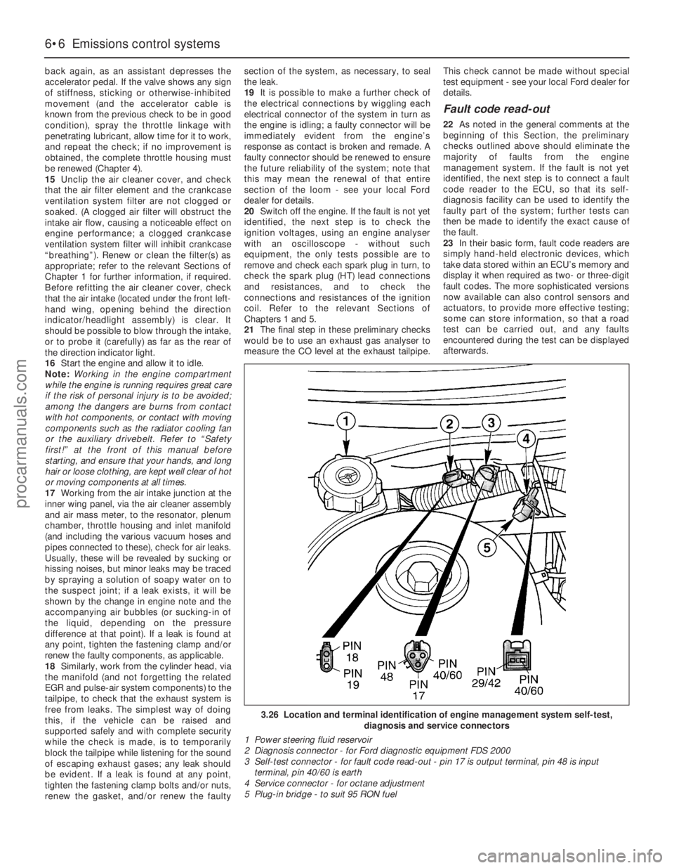
Fault code read-out
22As noted in the general comments at the
beginning of this Section, the preliminary
checks outlined above should eliminate the
majority of faults from the engine
management system. If the fault is not yet
identified, the next step is to connect a fault
code reader to the ECU, so that its self-
diagnosis facility can be used to identify the
faulty part of the system; further tests can
then be made to identify the exact cause of
the fault.
23In their basic form, fault code readers are
simply hand-held electronic devices, which
take data stored within an ECU’s memory and
display it when required as two- or three-digit
fault codes. The more sophisticated versions
now available can also control sensors and
actuators, to provide more effective testing;
some can store information, so that a road
test can be carried out, and any faults
encountered during the test can be displayed
afterwards.
6•6 Emissions control systems
3.26 Location and terminal identification of engine management system self-test,
diagnosis and service connectors
1 Power steering fluid reservoir
2 Diagnosis connector - for Ford diagnostic equipment FDS 2000
3 Self-test connector - for fault code read-out - pin 17 is output terminal, pin 48 is input
terminal, pin 40/60 is earth
4 Service connector - for octane adjustment
5 Plug-in bridge - to suit 95 RON fuel
procarmanuals.com
Page 204 of 279
BulbsWattage Type
Headlight main beam . . . . . . . . . . . . . . . . . . . . . . . . . . . . . . . . . . . . . . . 55 Halogen
Headlight dipped beam . . . . . . . . . . . . . . . . . . . . . . . . . . . . . . . . . . . . . . 55 Halogen
Foglights . . . . . . . . . . . . . . . . . . . . . . . . . . . . . . . . . . . . . . . . . . . . . . . . . 55 Halogen
Sidelights . . . . . . . . . . . . . . . . . . . . . . . . . . . . . . . . . . . . . . . . . . . . . . . . . 5 Wedge
Direction indicator lights . . . . . . . . . . . . . . . . . . . . . . . . . . . . . . . . . . . . . 21 Bayonet
Side repeater lights . . . . . . . . . . . . . . . . . . . . . . . . . . . . . . . . . . . . . . . . . 5 Wedge
Stop-lights . . . . . . . . . . . . . . . . . . . . . . . . . . . . . . . . . . . . . . . . . . . . . . . . 21 Bayonet
Reversing lights . . . . . . . . . . . . . . . . . . . . . . . . . . . . . . . . . . . . . . . . . . . . 21 Bayonet
Rear fog/tail lights (Saloon and Estate) . . . . . . . . . . . . . . . . . . . . . . . . . . 21/4 Bayonet
Rear tail light (Saloon and Hatchback) . . . . . . . . . . . . . . . . . . . . . . . . . . 5 Bayonet
Number plate lights . . . . . . . . . . . . . . . . . . . . . . . . . . . . . . . . . . . . . . . . . 5 Festoon
Engine compartment . . . . . . . . . . . . . . . . . . . . . . . . . . . . . . . . . . . . . . . . 10 Wedge
Interior lights . . . . . . . . . . . . . . . . . . . . . . . . . . . . . . . . . . . . . . . . . . . . . . 10 Festoon
Reading light . . . . . . . . . . . . . . . . . . . . . . . . . . . . . . . . . . . . . . . . . . . . . . 5 Wedge
Torque wrench settingsNm lbf ft
Windscreen wiper motor bolts:
Into old motor (see text) . . . . . . . . . . . . . . . . . . . . . . . . . . . . . . . . . . . 8 6
Into new motor (see text) . . . . . . . . . . . . . . . . . . . . . . . . . . . . . . . . . . . 12 9
Body electrical system 12•3
12
Warning: Before carrying out any
work on the electrical system,
read through the precautions
given in “Safety first!” at the beginning of
this manual.The electrical system is of 12-volt negative
earth type. Power for the lights and all
electrical accessories is supplied by a
lead/acid battery which is charged by the
alternator.
This Chapter covers repair and service
procedures for the various electrical
components not associated with the engine.
Information on the battery, ignition system,alternator, and starter motor can be found in
Chapter 5.
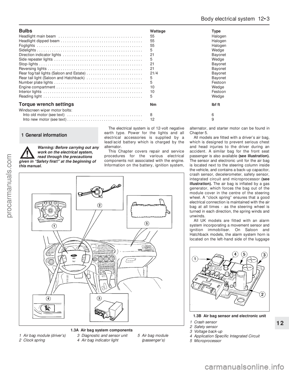
All models are fitted with a driver’s air bag,
which is designed to prevent serious chest
and head injuries to the driver during an
accident. A similar bag for the front seat
passenger is also available (see illustration).
The sensor and electronic unit for the air bag
is located next to the steering column inside
the vehicle, and contains a back-up capacitor,
crash sensor, decelerometer, safety sensor,
integrated circuit and microprocessor (see
illustration). The air bag is inflated by a gas
generator, which forces the bag out of the
module cover in the centre of the steering
wheel. A “clock spring” ensures that a good
electrical connection is maintained with the air
bag at all times - as the steering wheel is
turned in each direction, the spring winds and
unwinds.
All UK models are fitted with an alarm
system incorporating a movement sensor and
ignition immobiliser. On Saloon and
Hatchback models, the alarm system horn is
located on the left-hand side of the luggage
1 General information
1.3A Air bag system components
1 Air bag module (driver’s)
2 Clock spring3 Diagnostic and sensor unit
4 Air bag indicator light5 Air bag module
(passenger’s)
1.3B Air bag sensor and electronic unit
1 Crash sensor
2 Safety sensor
3 Voltage back-up
4 Application Specific Integrated Circuit
5 Microprocessor
procarmanuals.com
Page 214 of 279
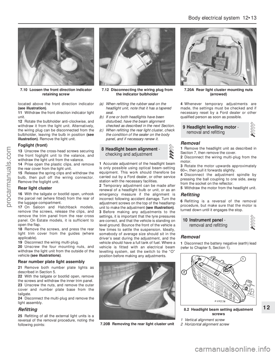
located above the front direction indicator
(see illustration).
11Withdraw the front direction indicator light
unit.
12Rotate the bulbholder anti-clockwise, and
withdraw it from the light unit. Alternatively,
the wiring plug can be disconnected from the
bulbholder, leaving the bulb in position (see
illustration). Remove the light unit.
Foglight (front)
13Unscrew the cross-head screws securing
the front foglight unit to the valance, and
withdraw the light unit from the valance.
14Prise open the plastic clips, and remove
the rear cover from the light unit.
15Release the spring clips and withdraw the
bulb, then pull off the wiring connector.
Remove the foglight unit.
Rear light cluster
16With the tailgate or bootlid open, unhook
the parcel net (where fitted) from the rear of
the luggage compartment.
17On Saloon and Hatchback models,
remove the screws, release the clips, and
remove the trim panel from the rear cross
panel. On Estate models, it is sufficient to
open the flap.
18Remove the screws, and press the rear
light trim cover from the guides (where
applicable).
19Disconnect the wiring multi-plug.
20Unscrew the four mounting nuts, and
withdraw the light unit from the outside of the
vehicle (see illustrations).
Rear number plate light assembly
21Remove both number plate lights as
described in Section 5.
22With the tailgate or bootlid open, remove
the screws and withdraw the inner trim panel.
23Unscrew the nuts, and remove the outer
cover and number plate base from the
tailgate.
24Disconnect the multi-plug and remove the
light assembly.
Refitting
25Refitting of all the external light units is a
reversal of the removal procedure, noting the
following points:(a) When refitting the rubber seal on the
headlight unit, note that it has a tapered
seat.
(b) If one or both headlights have been
disturbed, have the beam alignment
checked as described in the next Section.
(c) When refitting the rear light cluster, check
the condition of the sealer on the body
panel, and if necessary renew it.
1Accurate adjustment of the headlight beam
is only possible using optical beam-setting
equipment. This work should therefore be
carried out by a Ford dealer, or other service
station with the necessary facilities.
2Temporary adjustment can be made after
renewal of a headlight bulb or unit, or as an
emergency measure if the alignment is
incorrect following accident damage. Turn the
adjustment screws on the top of the headlamp
unit to make the adjustment (see illustration).
3Before making any adjustments to the
settings, it is important that the tyre pressures
are correct, and that the vehicle is standing on
level ground. Bounce the front of the vehicle a
few times to settle the suspension. Ideally,
somebody of average size should sit in the
driver’s seat during the adjustment, and the
vehicle should have a full tank of fuel. Where a
vehicle is fitted with an electrical beam
levelling system, set the switch to the “O”
position before making any adjustments.4Whenever temporary adjustments are
made, the settings must be checked and if
necessary reset by a Ford dealer or other
qualified person as soon as possible.
Removal
1Remove the headlight unit as described in
Section 7, then remove the cover.
2Disconnect the wiring multi-plug from the
motor.
3Rotate the motor upwards approximately
60°, then pull it forwards slightly.
4Disconnect the adjustment spindle by
pressing the ball coupling to one side, away
from the socket on the reflector.
5Withdraw the motor from the headlight unit.
Refitting
6Refitting is a reversal of the removal
procedure, but make sure that the motor is
turned down until it engages the stop.
Removal
1Disconnect the battery negative (earth) lead
(refer to Chapter 5, Section 1).
10 Instrument panel -
removal and refitting
9 Headlight levelling motor -
removal and refitting
8 Headlight beam alignment-
checking and adjustment
Body electrical system 12•13
12
7.20B Removing the rear light cluster unit
8.2 Headlight beam setting adjustment
screws
1 Vertical alignment screw
2 Horizontal alignment screw
7.10 Loosen the front direction indicator
retaining screw7.12 Disconnecting the wiring plug from
the indicator bulbholder7.20A Rear light cluster mounting nuts
(arrowed)
procarmanuals.com
Page 219 of 279
the specified mileage (or time) since the last
service has been reached.
4To reset the service interval system and
turn off the light, a switch inside the glovebox
must be depressed for a minimum of 4
seconds with the ignition switched on. This
should be carried out by a Ford dealer if the
vehicle is still in the warranty period.
Component renewal
5The following paragraphs describe brief
removal procedures for the auxiliary warning
system components. Disconnect the battery
negative (earth) lead before commencing
work (refer to Chapter 5, Section 1). Refitting
procedures are a reversal of removal.
Display warning bulb
6Remove the control assembly.
7Prise off the cover, and pull out the relevant
bulb and bulbholder.
Low air temperature warning sender
unit
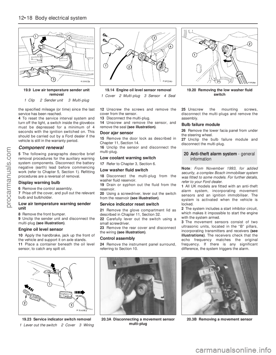
8Remove the front bumper.
9Unclip the sender unit and disconnect the
multi-plug (see illustration).
Engine oil level sensor
10Apply the handbrake, jack up the front of
the vehicle and support it on axle stands.
11Place a container beneath the oil level
sensor, to catch any spilt oil.12Unscrew the screws and remove the
cover from the sensor.
13Disconnect the multi-plug.
14Unscrew and remove the sensor, and
remove the seal (see illustration).
Door ajar sensor
15Remove the door lock as described in
Chapter 11, Section 14.
16Unclip the sensor and disconnect the
multi-plug.
Low coolant warning switch
17Refer to Chapter 3, Section 6.
Low washer fluid switch
18Disconnect the multi-plug from the
washer fluid reservoir.
19Drain or syphon out the fluid from the
reservoir.
20Using a screwdriver, lever out the switch
from the reservoir (see illustration).
Service indicator reset switch
21Remove the glove compartment lid as
described in Chapter 11, Section 32.
22Carefully lever out the switch using a
small screwdriver.
23Remove the rear cover and disconnect
the wiring (see illustration).
Control assembly
24Remove the instrument panel surround,
referring to Section 10.25Unscrew the mounting screws,
disconnect the multi-plugs and remove the
assembly.
Bulb failure module
26Remove the lower facia panel from under
the steering wheel.
27Unclip the bulb failure module and
disconnect the multi-plug.
Note: From November 1993, for added
security, a complex Bosch immobiliser system
was fitted to some models. For further details,
refer to your Ford dealer.
1All UK models are fitted with an anti-theft
alarm system, incorporating movement
sensors and an ignition immobiliser. The
system is activated when the vehicle is
locked.
2The system includes a start inhibitor circuit,
which makes it impossible to start the engine
with the system armed.
3The movement sensors consist of two
ultrasonic units, located in the “B” pillars,
incorporating transmitters and receivers (see
illustrations). The receivers check that the
echo frequency matches the original
frequency. If there is any significant
difference, the system triggers the alarm.
20 Anti-theft alarm system- general
information
12•18 Body electrical system
19.9 Low air temperature sender unit
removal
1 Clip 2 Sender unit 3 Multi-plug19.14 Engine oil level sensor removal
1 Cover 2 Multi-plug 3 Sensor 4 Seal19.20 Removing the low washer fluid
switch
19.23 Service indicator switch removal
1 Lever out the switch 2 Cover 3 Wiring20.3A Disconnecting a movement sensor
multi-plug20.3B Removing a movement sensor
procarmanuals.com
Page 269 of 279
6 Automatic transmission
REF•10Fault Finding
Note:Due to the complexity of the automatic transmission and its
electronic control system, it is difficult for the home mechanic to
properly diagnose and service this unit. For problems other than the
following, the vehicle should be taken to a dealer service department
or automatic transmission specialist.
Fluid leakage
m mAutomatic transmission fluid is usually deep red in colour. Fluid
leaks should not be confused with engine oil, which can easily be
blown onto the transmission by airflow.
m mTo determine the source of a leak, first remove all built-up dirt and
grime from the transmission housing and surrounding areas, using
a degreasing agent, or by steam-cleaning. Drive the vehicle at low
speed, so airflow will not blow the leak far from its source. Raise
and support the vehicle, and determine where the leak is coming
from. The following are common areas of leakage:
(a) Housing joints (Chapters 1 and 7, Part B).
(b) Dipstick tube (Chapters 1 and 7, Part B).
(c) Transmission-to-fluid cooler pipes/unions (Chapters 3 and 7,
Part B).
(d) Speedometer drive pinion O-ring (Chapter 7, Part B).
(e) Differential side gear oil seals (Chapter 7, Part B).
Transmission fluid brown, or has burned smell
m mTransmission fluid level low, or fluid in need of renewal (Chapter 1).
Transmission will not downshift (kickdown) with
accelerator pedal fully depressed
m mLow transmission fluid level (Chapter 1).
m mIncorrect selector cable adjustment (Chapter 7, Part B).
m mEngine management system fault (Chapters 1, 4, 5 and 6).
General gear selection problems
m
mChapter 7, Part B, deals with checking and adjusting the selector
cable on automatic transmissions. The following are common
problems which may be caused by a poorly-adjusted cable:
(a) Engine starting in gears other than Park or Neutral.
(b) Indicator on gear selector lever pointing to a gear other than the
one actually being used.
(c) Vehicle moves when in Park or Neutral.
(d) Poor gear shift quality or erratic gear changes.
Refer to Chapter 7, Part B for the selector cable adjustment
procedure.
Engine will not start in any gear, or starts in gears
other than Park or Neutral
m mIncorrect selector lever position sensor adjustment (Chapter 7,
Part B).
m mIncorrect selector cable adjustment (Chapter 7, Part B).
Transmission slips, shifts roughly, is noisy, or has no
drive in forward or reverse gears
m mThere are many probable causes for the above problems, but the
home mechanic should be concerned with only one possibility -
fluid level. Before taking the vehicle to a dealer or transmission
specialist, check the fluid level and condition of the fluid as
described in Chapter 1. Correct the fluid level as necessary, or
change the fluid if needed. If the problem persists, professional
help will be necessary.
7 Driveshafts
Clicking or knocking noise on turns (at slow speed
on full-lock)
m mLack of constant velocity joint lubricant (Chapter 8).
m mWorn outer constant velocity joint (Chapter 8).
Vibration when accelerating or decelerating
m
mWorn inner constant velocity joint (Chapter 8).
m mBent or distorted driveshaft (Chapter 8).
8 Braking system
Note:Before assuming that a brake problem exists, make sure that the tyres are in good condition and correctly inflated, that the front wheel
alignment is correct, and that the vehicle is not loaded with weight in an unequal manner. Apart from checking the condition of all pipe and hose
connections, any faults occurring on the Anti-lock Braking System (ABS) should be referred to a Ford dealer for diagnosis - the same applies to the
components of the Traction Control System (TCS).
Vehicle pulls to one side under braking
m mWorn, defective, damaged or contaminated front or rear brake
pads/shoes on one side (Chapter 1).
m mSeized or partially-seized front or rear brake caliper/wheel cylinder
piston (Chapter 9).
m mA mixture of brake pad/shoe lining materials fitted between sides
(Chapter 1).
m mBrake caliper mounting bolts loose (Chapter 9).
m mRear brake backplate mounting bolts loose (Chapter 9).
m mWorn or damaged steering or suspension components (Chap-
ter 10).
Noise (grinding or high-pitched squeal) when brakes
applied
m mBrake pad or shoe friction lining material worn down to metal
backing (Chapter 1).
m mExcessive corrosion of brake disc or drum (may be apparent after
the vehicle has been standing for some time) (Chapter 1).
m mForeign object (stone chipping, etc) trapped between brake disc
and splash shield (Chapter 1).
Excessive brake pedal travel
m mInoperative rear brake self-adjust mechanism (Chapter 9).
m mFaulty master cylinder (Chapter 9).
m mAir in hydraulic system (Chapter 9).
procarmanuals.com