1993 FORD MONDEO brake rotor
[x] Cancel search: brake rotorPage 61 of 279

and right-hand mountings. Do not yet
release the hoist; the weight of the
engine/transmission unit must not be
taken by the mountings until all are
correctly aligned.
(d) Fitting the Ford service tool in place of the
front mounting, tighten the
engine/transmission mounting fasteners
to their specified torque wrench settings,
and in the sequence described in Part B
of this Chapter, Section 4, paragraphs 49
and 50.
(e) Refill the cooling system (see Chapter 1).
(f) Refill the engine with oil, remembering
that you are advised to fit a new filter (see
Chapter 1).
(g) Check for signs of oil or coolant leaks
once the engine has been restarted and
warmed-up to normal operating
temperature.
Removal
Note:While this task is theoretically possible
when the engine is in place in the vehicle, in
practice, it requires so much preliminary
dismantling, and is so difficult to carry out due
to the restricted access, that owners are
advised to remove the engine from the vehicle
first. Note, however, that the oil pumppressure relief valve can be removed with the
engine in situ - see paragraph 8.
In addition to the new pump gasket and
other replacement parts required, read
through Section 15, and ensure that the
necessary tools and facilities are available.
1Remove the timing belt (see Section 10).
2Withdraw the crankshaft toothed pulley
and the thrustwasher behind it, noting which
way round the thrustwasher is fitted (see
Section 11).
3Remove the sump (see Section 15).
4Undo the screws securing the oil pump
pick-up/strainer pipe to the pump, then
unscrew the nut and withdraw the oil pump
pick-up/strainer pipe. Discard the gasket.
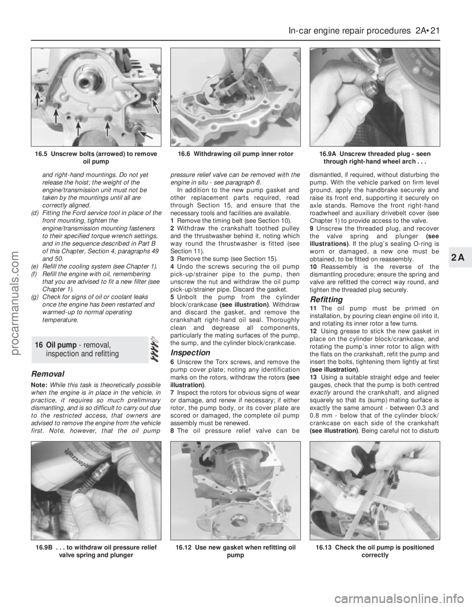
5Unbolt the pump from the cylinder
block/crankcase (see illustration). Withdraw
and discard the gasket, and remove the
crankshaft right-hand oil seal. Thoroughly
clean and degrease all components,
particularly the mating surfaces of the pump,
the sump, and the cylinder block/crankcase.
Inspection
6Unscrew the Torx screws, and remove the
pump cover plate; noting any identification
marks on the rotors, withdraw the rotors (see
illustration).
7Inspect the rotors for obvious signs of wear
or damage, and renew if necessary; if either
rotor, the pump body, or its cover plate are
scored or damaged, the complete oil pump
assembly must be renewed.
8The oil pressure relief valve can bedismantled, if required, without disturbing the
pump. With the vehicle parked on firm level
ground, apply the handbrake securely and
raise its front end, supporting it securely on
axle stands. Remove the front right-hand
roadwheel and auxiliary drivebelt cover (see
Chapter 1) to provide access to the valve.
9Unscrew the threaded plug, and recover
the valve spring and plunger (see
illustrations). If the plug’s sealing O-ring is
worn or damaged, a new one must be
obtained, to be fitted on reassembly.
10Reassembly is the reverse of the
dismantling procedure; ensure the spring and
valve are refitted the correct way round, and
tighten the threaded plug securely.
Refitting
11The oil pump must be primed on
installation, by pouring clean engine oil into it,
and rotating its inner rotor a few turns.
12Using grease to stick the new gasket in
place on the cylinder block/crankcase, and
rotating the pump’s inner rotor to align with
the flats on the crankshaft, refit the pump and
insert the bolts, tightening them lightly at first
(see illustration).
13Using a suitable straight edge and feeler
gauges, check that the pump is both centred
exactlyaround the crankshaft, and aligned
squarely so that its (sump) mating surface is
exactly the same amount - between 0.3 and
0.8 mm - below that of the cylinder block/
crankcase on each side of the crankshaft
(see illustration). Being careful not to disturb
16 Oil pump - removal,
inspection and refitting
In-car engine repair procedures 2A•21
2A
16.9B . . . to withdraw oil pressure relief
valve spring and plunger16.12 Use new gasket when refitting oil
pump16.13 Check the oil pump is positioned
correctly
16.5 Unscrew bolts (arrowed) to remove
oil pump16.6 Withdrawing oil pump inner rotor16.9A Unscrew threaded plug - seen
through right-hand wheel arch . . .
procarmanuals.com
Page 274 of 279

REF•15Glossary of Technical Terms
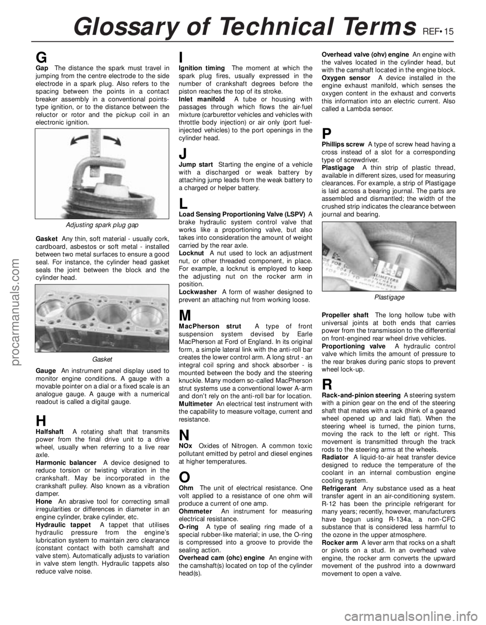
GGapThe distance the spark must travel in
jumping from the centre electrode to the side
electrode in a spark plug. Also refers to the
spacing between the points in a contact
breaker assembly in a conventional points-
type ignition, or to the distance between the
reluctor or rotor and the pickup coil in an
electronic ignition.
GasketAny thin, soft material - usually cork,
cardboard, asbestos or soft metal - installed
between two metal surfaces to ensure a good
seal. For instance, the cylinder head gasket
seals the joint between the block and the
cylinder head.
GaugeAn instrument panel display used to
monitor engine conditions. A gauge with a
movable pointer on a dial or a fixed scale is an
analogue gauge. A gauge with a numerical
readout is called a digital gauge.
HHalfshaftA rotating shaft that transmits
power from the final drive unit to a drive
wheel, usually when referring to a live rear
axle.
Harmonic balancerA device designed to
reduce torsion or twisting vibration in the
crankshaft. May be incorporated in the
crankshaft pulley. Also known as a vibration
damper.
HoneAn abrasive tool for correcting small
irregularities or differences in diameter in an
engine cylinder, brake cylinder, etc.
Hydraulic tappetA tappet that utilises
hydraulic pressure from the engine’s
lubrication system to maintain zero clearance
(constant contact with both camshaft and
valve stem). Automatically adjusts to variation
in valve stem length. Hydraulic tappets also
reduce valve noise.
IIgnition timingThe moment at which the
spark plug fires, usually expressed in the
number of crankshaft degrees before the
piston reaches the top of its stroke.
Inlet manifoldA tube or housing with
passages through which flows the air-fuel
mixture (carburettor vehicles and vehicles with
throttle body injection) or air only (port fuel-
injected vehicles) to the port openings in the
cylinder head.
JJump startStarting the engine of a vehicle
with a discharged or weak battery by
attaching jump leads from the weak battery to
a charged or helper battery.
LLoad Sensing Proportioning Valve (LSPV)A
brake hydraulic system control valve that
works like a proportioning valve, but also
takes into consideration the amount of weight
carried by the rear axle.
LocknutA nut used to lock an adjustment
nut, or other threaded component, in place.
For example, a locknut is employed to keep
the adjusting nut on the rocker arm in
position.
LockwasherA form of washer designed to
prevent an attaching nut from working loose.
MMacPherson strutA type of front
suspension system devised by Earle
MacPherson at Ford of England. In its original
form, a simple lateral link with the anti-roll bar
creates the lower control arm. A long strut - an
integral coil spring and shock absorber - is
mounted between the body and the steering
knuckle. Many modern so-called MacPherson
strut systems use a conventional lower A-arm
and don’t rely on the anti-roll bar for location.
MultimeterAn electrical test instrument with
the capability to measure voltage, current and
resistance.
NNOxOxides of Nitrogen. A common toxic
pollutant emitted by petrol and diesel engines
at higher temperatures.
OOhmThe unit of electrical resistance. One
volt applied to a resistance of one ohm will
produce a current of one amp.
OhmmeterAn instrument for measuring
electrical resistance.
O-ringA type of sealing ring made of a
special rubber-like material; in use, the O-ring
is compressed into a groove to provide the
sealing action.
Overhead cam (ohc) engineAn engine with
the camshaft(s) located on top of the cylinder
head(s).Overhead valve (ohv) engineAn engine with
the valves located in the cylinder head, but
with the camshaft located in the engine block.
Oxygen sensorA device installed in the
engine exhaust manifold, which senses the
oxygen content in the exhaust and converts
this information into an electric current. Also
called a Lambda sensor.
PPhillips screwA type of screw head having a
cross instead of a slot for a corresponding
type of screwdriver.
PlastigageA thin strip of plastic thread,
available in different sizes, used for measuring
clearances. For example, a strip of Plastigage
is laid across a bearing journal. The parts are
assembled and dismantled; the width of the
crushed strip indicates the clearance between
journal and bearing.
Propeller shaftThe long hollow tube with
universal joints at both ends that carries
power from the transmission to the differential
on front-engined rear wheel drive vehicles.
Proportioning valveA hydraulic control
valve which limits the amount of pressure to
the rear brakes during panic stops to prevent
wheel lock-up.
RRack-and-pinion steeringA steering system
with a pinion gear on the end of the steering
shaft that mates with a rack (think of a geared
wheel opened up and laid flat). When the
steering wheel is turned, the pinion turns,
moving the rack to the left or right. This
movement is transmitted through the track
rods to the steering arms at the wheels.
RadiatorA liquid-to-air heat transfer device
designed to reduce the temperature of the
coolant in an internal combustion engine
cooling system.
RefrigerantAny substance used as a heat
transfer agent in an air-conditioning system.
R-12 has been the principle refrigerant for
many years; recently, however, manufacturers
have begun using R-134a, a non-CFC
substance that is considered less harmful to
the ozone in the upper atmosphere.
Rocker armA lever arm that rocks on a shaft
or pivots on a stud. In an overhead valve
engine, the rocker arm converts the upward
movement of the pushrod into a downward
movement to open a valve.
Adjusting spark plug gap
Plastigage
Gasket
procarmanuals.com