1993 FORD MONDEO sensor
[x] Cancel search: sensorPage 59 of 279
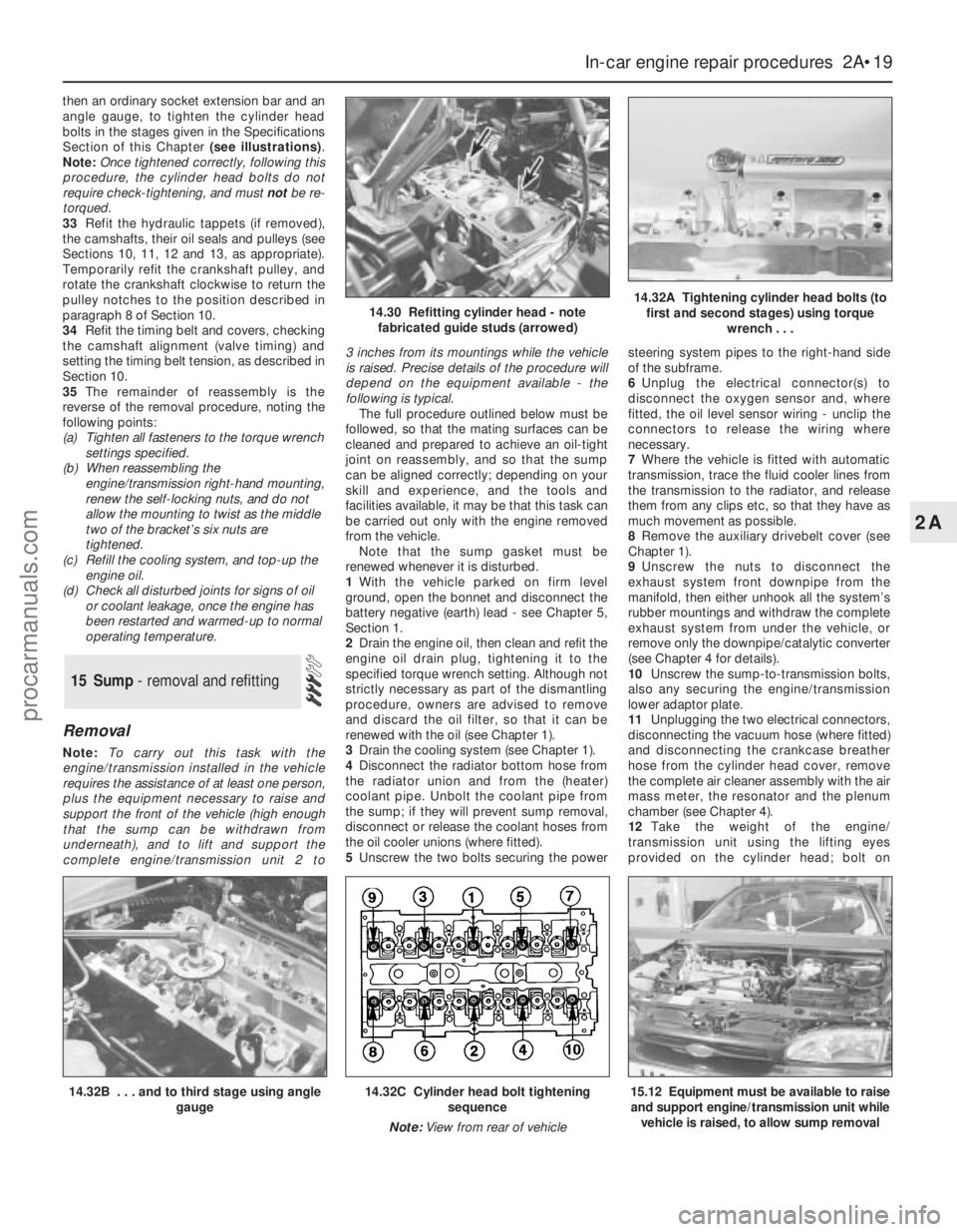
then an ordinary socket extension bar and an
angle gauge, to tighten the cylinder head
bolts in the stages given in the Specifications
Section of this Chapter (see illustrations).
Note:Once tightened correctly, following this
procedure, the cylinder head bolts do not
require check-tightening, and must notbe re-
torqued.
33Refit the hydraulic tappets (if removed),
the camshafts, their oil seals and pulleys (see
Sections 10, 11, 12 and 13, as appropriate).
Temporarily refit the crankshaft pulley, and
rotate the crankshaft clockwise to return the
pulley notches to the position described in
paragraph 8 of Section 10.
34Refit the timing belt and covers, checking
the camshaft alignment (valve timing) and
setting the timing belt tension, as described in
Section 10.
35The remainder of reassembly is the
reverse of the removal procedure, noting the
following points:
(a) Tighten all fasteners to the torque wrench
settings specified.
(b) When reassembling the
engine/transmission right-hand mounting,
renew the self-locking nuts, and do not
allow the mounting to twist as the middle
two of the bracket’s six nuts are
tightened.
(c) Refill the cooling system, and top-up the
engine oil.
(d) Check all disturbed joints for signs of oil
or coolant leakage, once the engine has
been restarted and warmed-up to normal
operating temperature.
Removal
Note:To carry out this task with the
engine/transmission installed in the vehicle
requires the assistance of at least one person,
plus the equipment necessary to raise and
support the front of the vehicle (high enough
that the sump can be withdrawn from
underneath), and to lift and support the
complete engine/transmission unit 2 to 3 inches from its mountings while the vehicle
is raised. Precise details of the procedure will
depend on the equipment available - the
following is typical.
The full procedure outlined below must be
followed, so that the mating surfaces can be
cleaned and prepared to achieve an oil-tight
joint on reassembly, and so that the sump
can be aligned correctly; depending on your
skill and experience, and the tools and
facilities available, it may be that this task can
be carried out only with the engine removed
from the vehicle.
Note that the sump gasket must be
renewed whenever it is disturbed.
1With the vehicle parked on firm level
ground, open the bonnet and disconnect the
battery negative (earth) lead - see Chapter 5,
Section 1.
2Drain the engine oil, then clean and refit the
engine oil drain plug, tightening it to the
specified torque wrench setting. Although not
strictly necessary as part of the dismantling
procedure, owners are advised to remove
and discard the oil filter, so that it can be
renewed with the oil (see Chapter 1).
3Drain the cooling system (see Chapter 1).
4Disconnect the radiator bottom hose from
the radiator union and from the (heater)
coolant pipe. Unbolt the coolant pipe from
the sump; if they will prevent sump removal,
disconnect or release the coolant hoses from
the oil cooler unions (where fitted).
5Unscrew the two bolts securing the powersteering system pipes to the right-hand side
of the subframe.
6Unplug the electrical connector(s) to
disconnect the oxygen sensor and, where
fitted, the oil level sensor wiring - unclip the
connectors to release the wiring where
necessary.
7Where the vehicle is fitted with automatic
transmission, trace the fluid cooler lines from
the transmission to the radiator, and release
them from any clips etc, so that they have as
much movement as possible.
8Remove the auxiliary drivebelt cover (see
Chapter 1).
9Unscrew the nuts to disconnect the
exhaust system front downpipe from the
manifold, then either unhook all the system’s
rubber mountings and withdraw the complete
exhaust system from under the vehicle, or
remove only the downpipe/catalytic converter
(see Chapter 4 for details).
10Unscrew the sump-to-transmission bolts,
also any securing the engine/transmission
lower adaptor plate.
11Unplugging the two electrical connectors,
disconnecting the vacuum hose (where fitted)
and disconnecting the crankcase breather
hose from the cylinder head cover, remove
the complete air cleaner assembly with the air
mass meter, the resonator and the plenum
chamber (see Chapter 4).
12Take the weight of the engine/
transmission unit using the lifting eyes
provided on the cylinder head; bolt on
15 Sump - removal and refitting
In-car engine repair procedures 2A•19
2A
14.32B . . . and to third stage using angle
gauge14.32C Cylinder head bolt tightening
sequence
Note:View from rear of vehicle15.12 Equipment must be available to raise
and support engine/transmission unit while
vehicle is raised, to allow sump removal
14.30 Refitting cylinder head - note
fabricated guide studs (arrowed)14.32A Tightening cylinder head bolts (to
first and second stages) using torque
wrench . . .
procarmanuals.com
Page 62 of 279
the gasket, move the pump into the correct
position, and tighten its bolts to the specified
torque wrench setting.
14Check that the pump is correctly located;
if necessary, unbolt it again, and repeat the
full procedure to ensure that the pump is
correctly aligned.
15Fit a new crankshaft right-hand oil seal
(see Section 20).
16Using grease to stick the gasket in place
on the pump, refit the pick-up/strainer pipe,
tightening its screws and nut to their specified
torque wrench settings (see illustration).
17The remainder of reassembly is the
reverse of the removal procedure, referring to
the relevant text for details where required.
1Drain the cooling system (see Chapter 1).
Disconnect the coolant hoses from the oil
cooler.
2Unscrew the oil filter (see Chapter 1) -
catch any escaping oil in a drip tray.
3Unscrew the filter adaptor from the oil
pump, and withdraw the oil cooler; note how
its unions are aligned, and be prepared for oil
loss from the cooler.
4Refitting is the reverse of the removal
procedure, noting the following points:(a) Renew all O-rings and seals disturbed on
removal.
(b) Align the cooler’s unions as noted on
removal, and tighten the adaptor to the
specified torque wrench setting.
(c) Refill the cooling system (see Chapter 1).
(d) Refit the oil filter, then check the engine
oil level, and top-up as necessary (see
Chapter 1).
(e) Check for signs of oil or coolant leaks once
the engine has been restarted and warmed-
up to normal operating temperature.
1With the vehicle parked on firm level
ground, open the bonnet and disconnect the
battery negative (earth) lead - see Chapter 5,
Section 1.
2Raise the front of the vehicle, and support it
securely on axle stands.
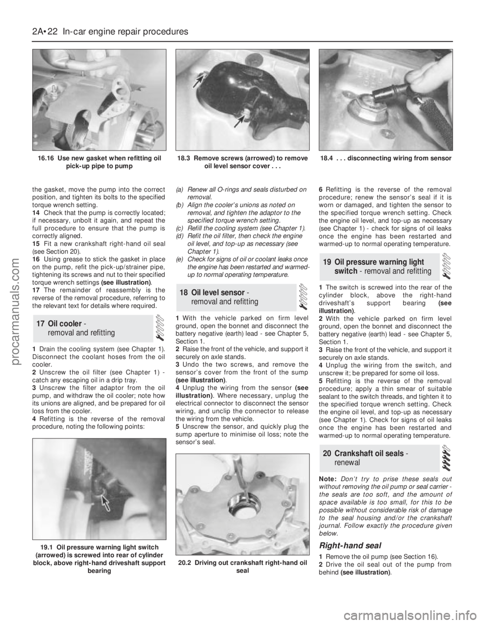
3Undo the two screws, and remove the
sensor’s cover from the front of the sump
(see illustration).
4Unplug the wiring from the sensor (see
illustration). Where necessary, unplug the
electrical connector to disconnect the sensor
wiring, and unclip the connector to release
the wiring from the vehicle.
5Unscrew the sensor, and quickly plug the
sump aperture to minimise oil loss; note the
sensor’s seal.6Refitting is the reverse of the removal
procedure; renew the sensor’s seal if it is
worn or damaged, and tighten the sensor to
the specified torque wrench setting. Check
the engine oil level, and top-up as necessary
(see Chapter 1) - check for signs of oil leaks
once the engine has been restarted and
warmed-up to normal operating temperature.
1The switch is screwed into the rear of the
cylinder block, above the right-hand
driveshaft’s support bearing (see
illustration).
2With the vehicle parked on firm level
ground, open the bonnet and disconnect the
battery negative (earth) lead - see Chapter 5,
Section 1.
3Raise the front of the vehicle, and support it
securely on axle stands.
4Unplug the wiring from the switch, and
unscrew it; be prepared for some oil loss.
5Refitting is the reverse of the removal
procedure; apply a thin smear of suitable
sealant to the switch threads, and tighten it to
the specified torque wrench setting. Check
the engine oil level, and top-up as necessary
(see Chapter 1). Check for signs of oil leaks
once the engine has been restarted and
warmed-up to normal operating temperature.
Note:Don’t try to prise these seals out
without removing the oil pump or seal carrier -
the seals are too soft, and the amount of
space available is too small, for this to be
possible without considerable risk of damage
to the seal housing and/or the crankshaft
journal. Follow exactly the procedure given
below.
Right-hand seal
1Remove the oil pump (see Section 16).
2Drive the oil seal out of the pump from
behind (see illustration).
20 Crankshaft oil seals -
renewal
19 Oil pressure warning light
switch - removal and refitting
18 Oil level sensor-
removal and refitting
17 Oil cooler -
removal and refitting
2A•22 In-car engine repair procedures
16.16 Use new gasket when refitting oil
pick-up pipe to pump18.3 Remove screws (arrowed) to remove
oil level sensor cover . . .18.4 . . . disconnecting wiring from sensor
19.1 Oil pressure warning light switch
(arrowed) is screwed into rear of cylinder
block, above right-hand driveshaft support
bearing
20.2 Driving out crankshaft right-hand oil
seal
procarmanuals.com
Page 64 of 279
Removal
1Remove the transmission (see the relevant
Part of Chapter 7). Now is a good time to
check components such as oil seals and
renew them if necessary.
2Where appropriate, remove the clutch
(Chapter 8). Now is a good time to check or
renew the clutch components and pilot
bearing.
3Use a centre-punch or paint to make
alignment marks on the flywheel/driveplate
and crankshaft, to ensure correct alignment
during refitting.
4Prevent the flywheel/driveplate from
turning by locking the ring gear teeth, or by
bolting a strap between the flywheel/
driveplate and the cylinder block/
crankcase. Slacken the bolts evenly until all
are free.
5Remove each bolt in turn, and ensure that
new replacements are obtained for
reassembly; these bolts are subjected to
severe stresses, and so must be renewed,
regardless of their apparent condition,
whenever they are disturbed.
6Noting the reinforcing plate (automatic
transmission-equipped models only),
withdraw the flywheel/driveplate; do not drop
it - it is very heavy.
Inspection
7Clean the flywheel/driveplate to remove
grease and oil. Inspect the surface for cracks,
rivet grooves, burned areas and score marks.
Light scoring can be removed with emery
cloth. Check for cracked and broken ring gear
teeth. Lay the flywheel/driveplate on a flat
surface, and use a straight edge to check for
warpage.
8Clean and inspect the mating surfaces of
the flywheel/driveplate and the crankshaft. If
the crankshaft left-hand seal is leaking, renew
it (see Section 20) before refitting the
flywheel/driveplate.
9While the flywheel/driveplate is removed,clean carefully its inboard (right-hand) face,
particularly the recesses which serve as the
reference points for the crankshaft
speed/position sensor. Clean the sensor’s tip,
and check that the sensor is securely
fastened.
Refitting
10On refitting, ensure that the
engine/transmission adaptor plate is in place
(where necessary), then fit the
flywheel/driveplate to the crankshaft so that
all bolt holes align - it will fit only one way -
check this using the marks made on removal.
Do not forget the reinforcing plate (where
fitted).
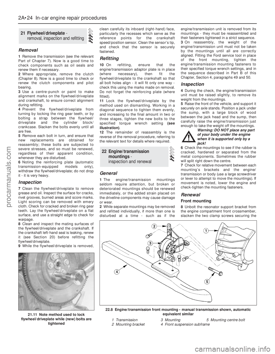
11Lock the flywheel/driveplate by the
method used on dismantling. Working in a
diagonal sequence to tighten them evenly,
and increasing to the final amount in two or
three stages, tighten the new bolts to the
specified torque wrench setting (see
illustration).
12The remainder of reassembly is the
reverse of the removal procedure, referring to
the relevant text for details where required.
General
1The engine/transmission mountings
seldom require attention, but broken or
deteriorated mountings should be renewed
immediately, or the added strain placed on
the driveline components may cause damage
or wear.
2While separate mountings may be removed
and refitted individually, if more than one is
disturbed at a time - such as if theengine/transmission unit is removed from its
mountings - they must be reassembled and
their fasteners tightened in a strict sequence.
3On reassembly, the weight of the
engine/transmission unit must not be taken
by the mountings until all are correctly
aligned. Fitting the Ford service tool in place
of the front mounting, tighten the
engine/transmission mounting fasteners to
their specified torque wrench settings, and in
the sequence described in Part B of this
Chapter, Section 4, paragraphs 49 and 50.
Inspection
4During the check, the engine/transmission
unit must be raised slightly, to remove its
weight from the mountings.
5Raise the front of the vehicle, and support it
securely on axle stands. Position a jack under
the sump, with a large block of wood
between the jack head and the sump, then
carefully raise the engine/transmission just
enough to take the weight off the mountings.
Warning: DO NOT place any part
of your body under the engine
when it is supported only by a
jack!
6Check the mountings to see if the rubber is
cracked, hardened or separated from the
metal components. Sometimes the rubber
will split right down the centre.
7Check for relative movement between each
mounting’s brackets and the engine/
transmission or body (use a large screwdriver
or lever to attempt to move the mountings). If
movement is noted, lower the engine and
check-tighten the mounting fasteners.
Renewal
Front mounting
8Unbolt the resonator support bracket from
the engine compartment front crossmember,
slacken the two clamp screws securing the
22 Engine/transmission
mountings -
inspection and renewal
21 Flywheel/driveplate -
removal, inspection and refitting
2A•24 In-car engine repair procedures
21.11 Note method used to lock
flywheel/driveplate while (new) bolts are
tightened
22.8 Engine/transmission front mounting - manual transmission shown, automatic
equivalent similar
1 Transmission 3 Mounting 5 Mounting centre bolt
2 Mounting bracket 4 Front suspension subframe
procarmanuals.com
Page 71 of 279
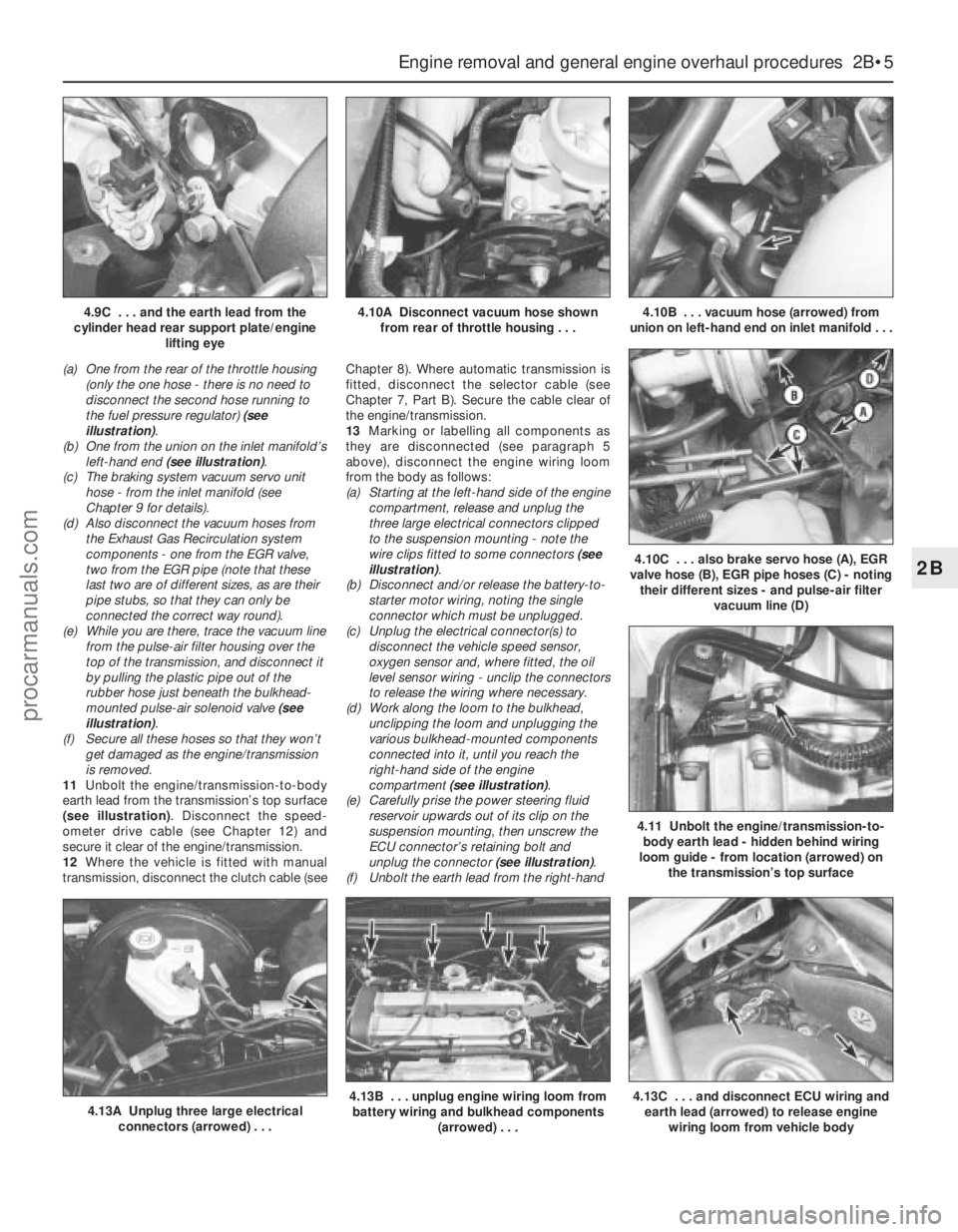
(a) One from the rear of the throttle housing
(only the one hose - there is no need to
disconnect the second hose running to
the fuel pressure regulator) (see
illustration).
(b) One from the union on the inlet manifold’s
left-hand end (see illustration).
(c) The braking system vacuum servo unit
hose - from the inlet manifold (see
Chapter 9 for details).
(d) Also disconnect the vacuum hoses from
the Exhaust Gas Recirculation system
components - one from the EGR valve,
two from the EGR pipe (note that these
last two are of different sizes, as are their
pipe stubs, so that they can only be
connected the correct way round).
(e) While you are there, trace the vacuum line
from the pulse-air filter housing over the
top of the transmission, and disconnect it
by pulling the plastic pipe out of the
rubber hose just beneath the bulkhead-
mounted pulse-air solenoid valve (see
illustration).
(f) Secure all these hoses so that they won’t
get damaged as the engine/transmission
is removed.
11Unbolt the engine/transmission-to-body
earth lead from the transmission’s top surface
(see illustration). Disconnect the speed-
ometer drive cable (see Chapter 12) and
secure it clear of the engine/transmission.
12Where the vehicle is fitted with manual
transmission, disconnect the clutch cable (seeChapter 8). Where automatic transmission is
fitted, disconnect the selector cable (see
Chapter 7, Part B). Secure the cable clear of
the engine/transmission.
13Marking or labelling all components as
they are disconnected (see paragraph 5
above), disconnect the engine wiring loom
from the body as follows:
(a) Starting at the left-hand side of the engine
compartment, release and unplug the
three large electrical connectors clipped
to the suspension mounting - note the
wire clips fitted to some connectors (see
illustration).
(b) Disconnect and/or release the battery-to-
starter motor wiring, noting the single
connector which must be unplugged.
(c) Unplug the electrical connector(s) to
disconnect the vehicle speed sensor,
oxygen sensor and, where fitted, the oil
level sensor wiring - unclip the connectors
to release the wiring where necessary.
(d) Work along the loom to the bulkhead,
unclipping the loom and unplugging the
various bulkhead-mounted components
connected into it, until you reach the
right-hand side of the engine
compartment (see illustration).
(e) Carefully prise the power steering fluid
reservoir upwards out of its clip on the
suspension mounting, then unscrew the
ECU connector’s retaining bolt and
unplug the connector (see illustration).
(f) Unbolt the earth lead from the right-hand
Engine removal and general engine overhaul procedures 2B•5
2B
4.13A Unplug three large electrical
connectors (arrowed) . . .4.13B . . . unplug engine wiring loom from
battery wiring and bulkhead components
(arrowed) . . .4.13C . . . and disconnect ECU wiring and
earth lead (arrowed) to release engine
wiring loom from vehicle body
4.9C . . . and the earth lead from the
cylinder head rear support plate/engine
lifting eye4.10A Disconnect vacuum hose shown
from rear of throttle housing . . .4.10B . . . vacuum hose (arrowed) from
union on left-hand end on inlet manifold . . .
4.10C . . . also brake servo hose (A), EGR
valve hose (B), EGR pipe hoses (C) - noting
their different sizes - and pulse-air filter
vacuum line (D)
4.11 Unbolt the engine/transmission-to-
body earth lead - hidden behind wiring
loom guide - from location (arrowed) on
the transmission’s top surface
procarmanuals.com
Page 75 of 279
gear linkage heat shield. Reconnect the
gearchange linkage and transmission support
rods to the transmission, adjusting the linkage
using the marks made on removal (see
Chapter 7, Part A, for details).
56Re-install the remaining components and
fasteners in the reverse order of removal.
57Add coolant, engine oil and transmission
fluids as needed (see Chapter 1).
58Run the engine, and check for proper
operation and the absence of leaks. Shut off
the engine, and recheck the fluid levels.
59Remember that, since the front suspension
subframe and steering gear have been
disturbed, the wheel alignment and steering
angles must be checked fully and carefully as
soon as possible, with any necessary
adjustments being made. This operation is best
carried out by an experienced mechanic, using
proper checking equipment; the vehicle should
therefore be taken to a Ford dealer or similarly-
qualified person for attention.
1It is much easier to dismantle and work on
the engine if it is mounted on a portable engine
stand. These stands can often be hired from a
tool hire shop. Before the engine is mounted
on a stand, the flywheel/driveplate should be
removed (Part A of this Chapter, Section 21)
so that the stand bolts can be tightened into
the end of the cylinder block/crankcase.
2If a stand is not available, it is possible to
dismantle the engine with it mounted on
blocks, on a sturdy workbench or on the floor.
Be extra-careful not to tip or drop the engine
when working without a stand.
3If you are going to obtain a reconditioned
engine, all external components must be
removed first, to be transferred to the
replacement engine (just as they will if you are
doing a complete engine overhaul yourself).
Note:When removing the external
components from the engine, pay close
attention to details that may be helpful or
important during refitting. Note the fitted
position of gaskets, seals, spacers, pins,
washers, bolts and other small items.These
external components include the following:
(a) Alternator and brackets (Chapter 5).
(b) HT leads and spark plugs (Chapter 1).
(c) Thermostat and housing (Chapter 3).
(d) Dipstick tube.
(e) Fuel injection system components
(Chapter 4).
(f) All electrical switches and sensors - refer
to the appropriate Chapter.
(g) Inlet and exhaust manifolds (Part A of this
Chapter).
(h) Oil filter (Chapter 1).
(i) Engine/transmission mounting brackets
(Part A of this Chapter, Section 22).
(j) Flywheel/driveplate (Part A of this
Chapter, Section 21).
4If you are obtaining a “short” engine (whichconsists of the engine cylinder
block/crankcase, crankshaft, pistons and
connecting rods all assembled), then the
cylinder head, sump, oil pump, and timing belt
will have to be removed also.
5If you are planning a complete overhaul, the
engine can be dismantled and the internal
components removed in the following order.
(a) Inlet and exhaust manifolds (Part A of this
Chapter).
(b) Timing belt, toothed pulleys and
tensioner, and timing belt inner cover
(Part A of this Chapter).
(c) Cylinder head (Part A of this Chapter,
Section 14).
(d) Flywheel/driveplate (Part A of this
Chapter, Section 21).
(e) Sump (Part A of this Chapter, Section 15).
(f) Oil pump (Part A of this Chapter, Sec-
tion 16).
(g) Piston/connecting rod assemblies
(Section 9).
(h) Crankshaft (Section 10).
6Before beginning the dismantling andoverhaul procedures, make sure that you have
all of the correct tools necessary. Refer to the
introductory pages at the beginning of this
manual for further information.
Note:New and reconditioned cylinder heads
are available from the manufacturers, and
from engine overhaul specialists. Due to the
fact that some specialist tools are required for
the dismantling and inspection procedures,
and new components may not be readily
available (refer to Section 1 of this Part), it may
be more practical and economical for the
home mechanic to purchase a reconditioned
head, rather than to dismantle, inspect and
recondition the original head.
1Remove the camshafts and hydraulic
tappets (Part A of this Chapter, Section 13),
being careful to store the hydraulic tappets as
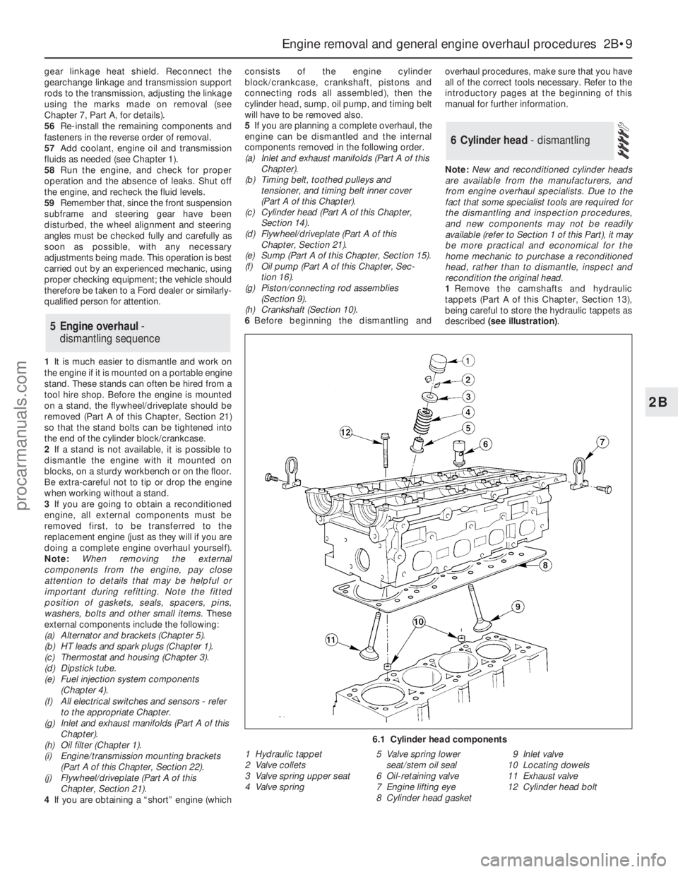
described (see illustration).
6 Cylinder head - dismantling
5 Engine overhaul-
dismantling sequence
Engine removal and general engine overhaul procedures 2B•9
2B
6.1 Cylinder head components
1 Hydraulic tappet
2 Valve collets
3 Valve spring upper seat
4 Valve spring5 Valve spring lower
seat/stem oil seal
6 Oil-retaining valve
7 Engine lifting eye
8 Cylinder head gasket9 Inlet valve
10 Locating dowels
11 Exhaust valve
12 Cylinder head bolt
procarmanuals.com
Page 79 of 279
remove the piston/connecting rod assemblies
may result in piston ring breakage.
7Slacken each of the big-end bearing cap
bolts half a turn at a time, until they can be
removed by hand. Remove the No 1 cap and
bearing shell. Don’t drop the shell out of the
cap.
8Remove the upper bearing shell, and push
the connecting rod/piston assembly out
through the top of the engine. Use a wooden
hammer handle to push on the connecting
rod’s bearing recess. If resistance is felt,
double-check that all of the ridge was
removed from the cylinder.
9Repeat the procedure for the remaining
cylinders.
10After removal, reassemble the big-end
bearing caps and shells on their respective
connecting rods, and refit the bolts finger-
tight. Leaving the old shells in place until
reassembly will help prevent the bearing
recesses from being accidentally nicked or
gouged. New shells should be used on
reassembly.
11Don’t attempt to separate the pistons
from the connecting rods - see Section 12.
Note:The crankshaft can be removed only
after the engine/transmission has been
removed from the vehicle. It is assumed that
the transmission and flywheel/driveplate,
timing belt, cylinder head, sump, oil pump
pick-up/strainer pipe and oil baffle, oil pump,
and piston/connecting rod assemblies, have
already been removed. The crankshaft left-
hand oil seal carrier must be unbolted from
the cylinder block/crankcase before
proceeding with crankshaft removal.
1Before the crankshaft is removed, check
the endfloat. Mount a DTI (Dial Test Indicator,
or dial gauge) with the stem in line with the
crankshaft and just touching the crankshaft
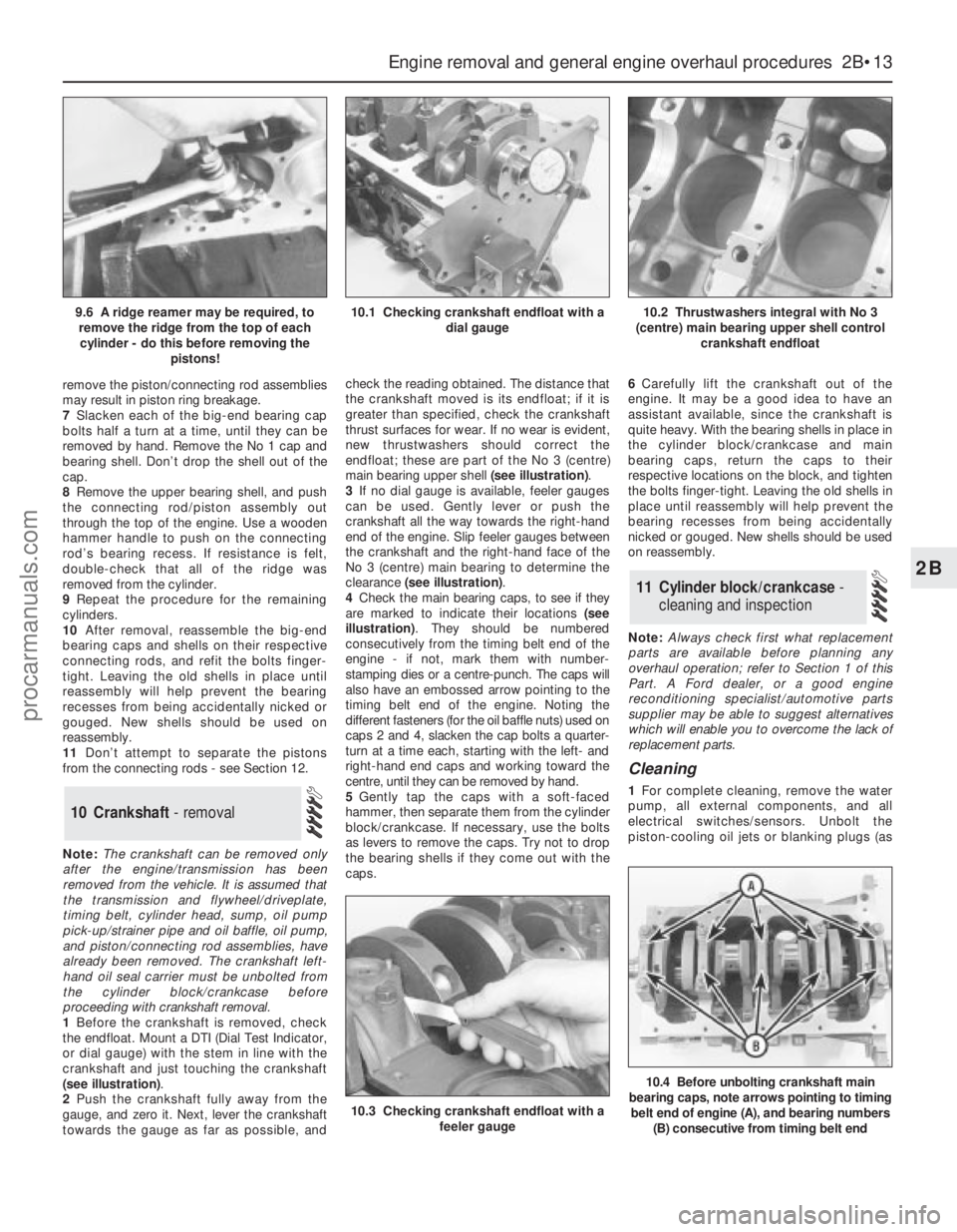
(see illustration).
2Push the crankshaft fully away from the
gauge, and zero it. Next, lever the crankshaft
towards the gauge as far as possible, andcheck the reading obtained. The distance that
the crankshaft moved is its endfloat; if it is
greater than specified, check the crankshaft
thrust surfaces for wear. If no wear is evident,
new thrustwashers should correct the
endfloat; these are part of the No 3 (centre)
main bearing upper shell (see illustration).
3If no dial gauge is available, feeler gauges
can be used. Gently lever or push the
crankshaft all the way towards the right-hand
end of the engine. Slip feeler gauges between
the crankshaft and the right-hand face of the
No 3 (centre) main bearing to determine the
clearance (see illustration).
4Check the main bearing caps, to see if they
are marked to indicate their locations (see
illustration). They should be numbered
consecutively from the timing belt end of the
engine - if not, mark them with number-
stamping dies or a centre-punch. The caps will
also have an embossed arrow pointing to the
timing belt end of the engine. Noting the
different fasteners (for the oil baffle nuts) used on
caps 2 and 4, slacken the cap bolts a quarter-
turn at a time each, starting with the left- and
right-hand end caps and working toward the
centre, until they can be removed by hand.
5Gently tap the caps with a soft-faced
hammer, then separate them from the cylinder
block/crankcase. If necessary, use the bolts
as levers to remove the caps. Try not to drop
the bearing shells if they come out with the
caps.6Carefully lift the crankshaft out of the
engine. It may be a good idea to have an
assistant available, since the crankshaft is
quite heavy. With the bearing shells in place in
the cylinder block/crankcase and main
bearing caps, return the caps to their
respective locations on the block, and tighten
the bolts finger-tight. Leaving the old shells in
place until reassembly will help prevent the
bearing recesses from being accidentally
nicked or gouged. New shells should be used
on reassembly.
Note:Always check first what replacement
parts are available before planning any
overhaul operation; refer to Section 1 of this
Part. A Ford dealer, or a good engine
reconditioning specialist/automotive parts
supplier may be able to suggest alternatives
which will enable you to overcome the lack of
replacement parts.
Cleaning
1For complete cleaning, remove the water
pump, all external components, and all
electrical switches/sensors. Unbolt the
piston-cooling oil jets or blanking plugs (as
11 Cylinder block/crankcase -
cleaning and inspection
10 Crankshaft - removal
Engine removal and general engine overhaul procedures 2B•13
2B
10.3 Checking crankshaft endfloat with a
feeler gauge
10.4 Before unbolting crankshaft main
bearing caps, note arrows pointing to timing
belt end of engine (A), and bearing numbers
(B) consecutive from timing belt end
9.6 A ridge reamer may be required, to
remove the ridge from the top of each
cylinder - do this before removing the
pistons!10.1 Checking crankshaft endfloat with a
dial gauge10.2 Thrustwashers integral with No 3
(centre) main bearing upper shell control
crankshaft endfloat
procarmanuals.com
Page 80 of 279
applicable); note that Ford state that the
piston-cooling oil jets (where fitted) must be
renewed whenever the engine is dismantled
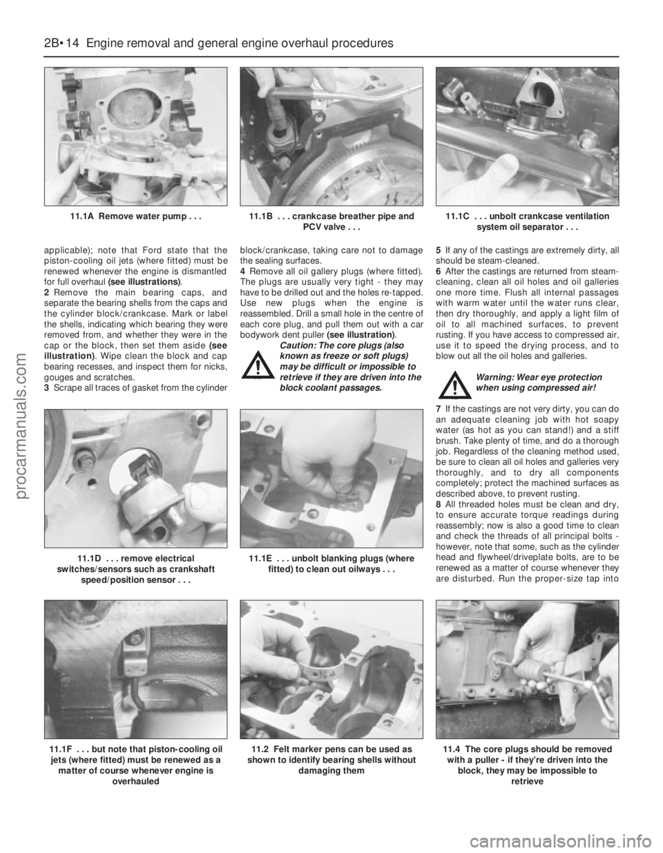
for full overhaul (see illustrations).
2Remove the main bearing caps, and
separate the bearing shells from the caps and
the cylinder block/crankcase. Mark or label
the shells, indicating which bearing they were
removed from, and whether they were in the
cap or the block, then set them aside (see
illustration). Wipe clean the block and cap
bearing recesses, and inspect them for nicks,
gouges and scratches.
3Scrape all traces of gasket from the cylinderblock/crankcase, taking care not to damage
the sealing surfaces.
4Remove all oil gallery plugs (where fitted).
The plugs are usually very tight - they may
have to be drilled out and the holes re-tapped.
Use new plugs when the engine is
reassembled. Drill a small hole in the centre of
each core plug, and pull them out with a car
bodywork dent puller (see illustration).
Caution: The core plugs (also
known as freeze or soft plugs)
may be difficult or impossible to
retrieve if they are driven into the
block coolant passages.5If any of the castings are extremely dirty, all
should be steam-cleaned.
6After the castings are returned from steam-
cleaning, clean all oil holes and oil galleries
one more time. Flush all internal passages
with warm water until the water runs clear,
then dry thoroughly, and apply a light film of
oil to all machined surfaces, to prevent
rusting. If you have access to compressed air,
use it to speed the drying process, and to
blow out all the oil holes and galleries.
Warning: Wear eye protection
when using compressed air!
7If the castings are not very dirty, you can do
an adequate cleaning job with hot soapy
water (as hot as you can stand!) and a stiff
brush. Take plenty of time, and do a thorough
job. Regardless of the cleaning method used,
be sure to clean all oil holes and galleries very
thoroughly, and to dry all components
completely; protect the machined surfaces as
described above, to prevent rusting.
8All threaded holes must be clean and dry,
to ensure accurate torque readings during
reassembly; now is also a good time to clean
and check the threads of all principal bolts -
however, note that some, such as the cylinder
head and flywheel/driveplate bolts, are to be
renewed as a matter of course whenever they
are disturbed. Run the proper-size tap into
2B•14 Engine removal and general engine overhaul procedures
11.1A Remove water pump . . .11.1B . . . crankcase breather pipe and
PCV valve . . .11.1C . . . unbolt crankcase ventilation
system oil separator . . .
11.1F . . . but note that piston-cooling oil
jets (where fitted) must be renewed as a
matter of course whenever engine is
overhauled11.2 Felt marker pens can be used as
shown to identify bearing shells without
damaging them
11.1D . . . remove electrical
switches/sensors such as crankshaft
speed/position sensor . . .11.1E . . . unbolt blanking plugs (where
fitted) to clean out oilways . . .
11.4 The core plugs should be removed
with a puller - if they’re driven into the
block, they may be impossible to
retrieve
procarmanuals.com
Page 89 of 279
Chapter 3
Cooling, heating, and air conditioning systems
Air conditioning system - general information
and precautions . . . . . . . . . . . . . . . . . . . . . . . . . . . . . . . . . . . . . . . . 11
Air conditioning system components - removal and refitting . . . . . . 12
Antifreeze - general information . . . . . . . . . . . . . . . . . . . . . . . . . . . . 2
Auxiliary drivebelt check and renewal . . . . . . . . . . . . . See Chapter 1
Coolant level check . . . . . . . . . . . . . . . . . . . . . . . . . . . See Chapter 1
Coolant renewal . . . . . . . . . . . . . . . . . . . . . . . . . . . . . . See Chapter 1
Cooling system checks (coolant leaks,
hose condition) . . . . . . . . . . . . . . . . . . . . . . . . . . . . . See Chapter 1
Cooling system electrical switches and sensors -
testing, removal and refitting . . . . . . . . . . . . . . . . . . . . . . . . . . . . . 6
Cooling system hoses - disconnection and renewal . . . . . . . . . . . . 3Cooling system servicing (draining, flushing
and refilling) . . . . . . . . . . . . . . . . . . . . . . . . . . . . . . . See Chapter 1
General information . . . . . . . . . . . . . . . . . . . . . . . . . . . . . . . . . . . . . . 1
Heater/air conditioning controls - removal and refitting . . . . . . . . . . 10
Heater/ventilation components - removal and refitting . . . . . . . . . . . 9
Pollen filter renewal . . . . . . . . . . . . . . . . . . . . . . . . . . . See Chapter 1
Radiator and expansion tank - removal, inspection
and refitting . . . . . . . . . . . . . . . . . . . . . . . . . . . . . . . . . . . . . . . . . . . . 7
Radiator electric cooling fan(s) - testing, removal and refitting . . . . . 5
Thermostat - removal, testing and refitting . . . . . . . . . . . . . . . . . . . . 4
Water pump - check, removal and refitting . . . . . . . . . . . . . . . . . . . . 8
Coolant
Mixture type . . . . . . . . . . . . . . . . . . . . . . . . . . . . . . . . . . . . . . . . . . . . . . See Chapter 1
Cooling system capacity . . . . . . . . . . . . . . . . . . . . . . . . . . . . . . . . . . . . . See Chapter 1
System pressure
Pressure test . . . . . . . . . . . . . . . . . . . . . . . . . . . . . . . . . . . . . . . . . . . . . . 1.2 bars - should hold this pressure for at least 10 seconds
Expansion tank filler cap
Pressure rating . . . . . . . . . . . . . . . . . . . . . . . . . . . . . . . . . . . . . . . . . . . . 1.2 bars approximately - see cap for actual value
Thermostat
Starts to open . . . . . . . . . . . . . . . . . . . . . . . . . . . . . . . . . . . . . . . . . . . . . 88°C
Radiator electric cooling fan
Switches on at:
Single-speed fans, two-speed fans - first stage . . . . . . . . . . . . . . . . . 100°C
Two-speed fans - second stage . . . . . . . . . . . . . . . . . . . . . . . . . . . . . 103°C
Switches off at:
Single-speed fans, two-speed fans - first stage . . . . . . . . . . . . . . . . . 93°C
Two-speed fans - second stage . . . . . . . . . . . . . . . . . . . . . . . . . . . . . 100°C
Coolant temperature sensor
Resistance:
At -40°C . . . . . . . . . . . . . . . . . . . . . . . . . . . . . . . . . . . . . . . . . . . . . . . . 860.0 to 900.0 kilohms
At 20°C . . . . . . . . . . . . . . . . . . . . . . . . . . . . . . . . . . . . . . . . . . . . . . . . 35.0 to 40.0 kilohms
At 100°C . . . . . . . . . . . . . . . . . . . . . . . . . . . . . . . . . . . . . . . . . . . . . . . 1.9 to 2.5 kilohms
At 120°C . . . . . . . . . . . . . . . . . . . . . . . . . . . . . . . . . . . . . . . . . . . . . . . 1.0 to 1.3 kilohms
Air conditioning system
Refrigerant . . . . . . . . . . . . . . . . . . . . . . . . . . . . . . . . . . . . . . . . . . . . . . . . R134a
3•1
Easy,suitable for
novice with little
experienceFairly easy,suitable
for beginner with
some experienceFairly difficult,suitable
for competent DIY
mechanicDifficult,suitable for
experienced DIY
mechanicVery difficult,
suitable for expert DIY
or professional
Degrees of difficulty
Specifications Contents
3
procarmanuals.com