1993 FORD MONDEO coolant reservoir
[x] Cancel search: coolant reservoirPage 17 of 279
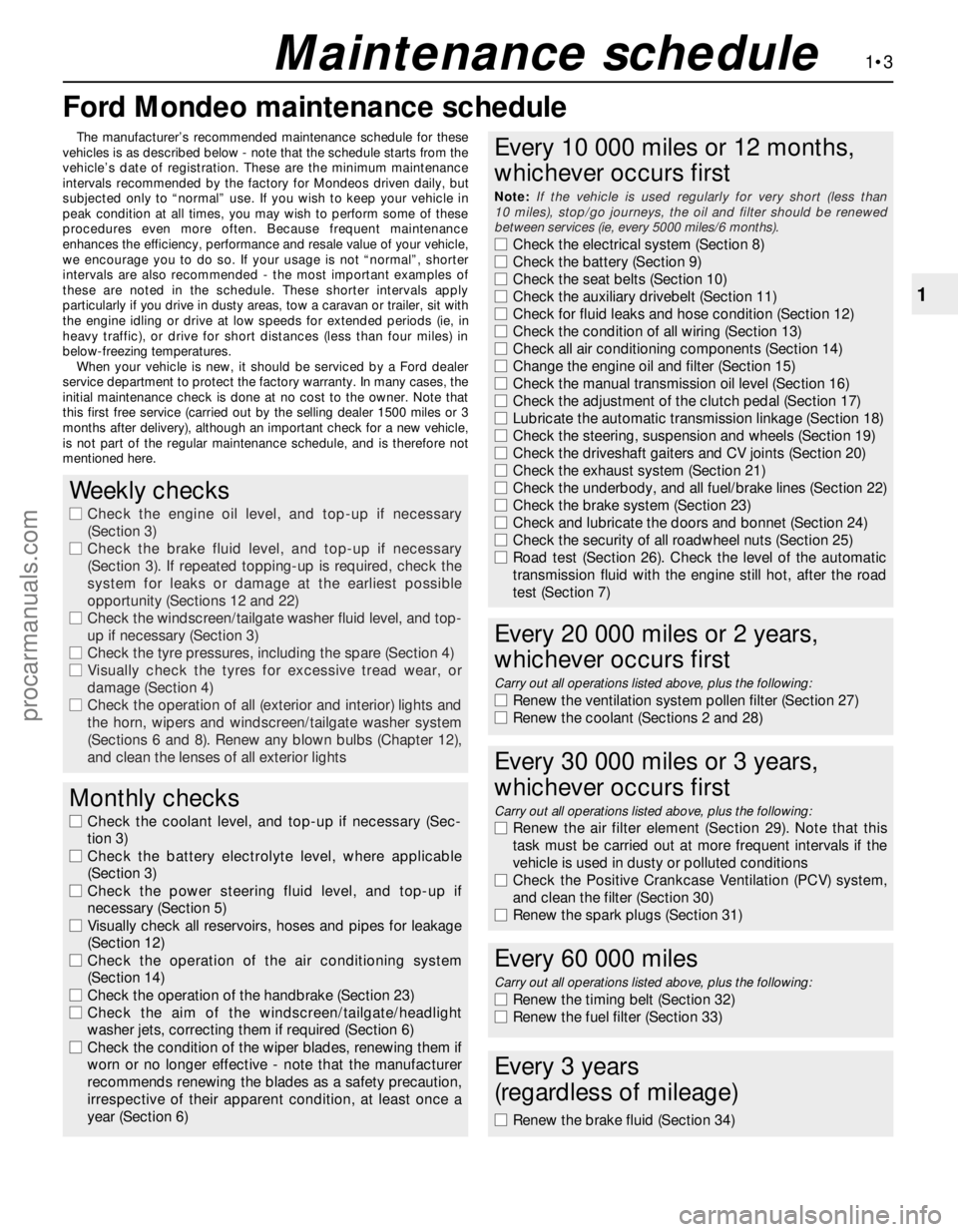
Ford Mondeo maintenance schedule
1•3
1
Maintenance schedule
The manufacturer’s recommended maintenance schedule for these
vehicles is as described below - note that the schedule starts from the
vehicle’s date of registration. These are the minimum maintenance
intervals recommended by the factory for Mondeos driven daily, but
subjected only to “normal” use. If you wish to keep your vehicle in
peak condition at all times, you may wish to perform some of these
procedures even more often. Because frequent maintenance
enhances the efficiency, performance and resale value of your vehicle,
we encourage you to do so. If your usage is not “normal”, shorter
intervals are also recommended - the most important examples of
these are noted in the schedule. These shorter intervals apply
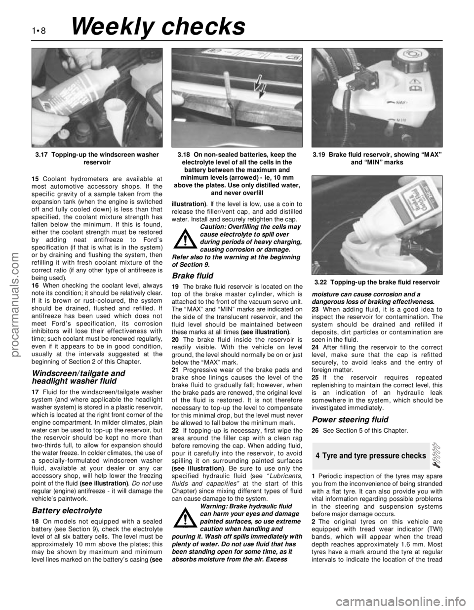
particularly if you drive in dusty areas, tow a caravan or trailer, sit with
the engine idling or drive at low speeds for extended periods (ie, in
heavy traffic), or drive for short distances (less than four miles) in
below-freezing temperatures.
When your vehicle is new, it should be serviced by a Ford dealer
service department to protect the factory warranty. In many cases, the
initial maintenance check is done at no cost to the owner. Note that
this first free service (carried out by the selling dealer 1500 miles or 3
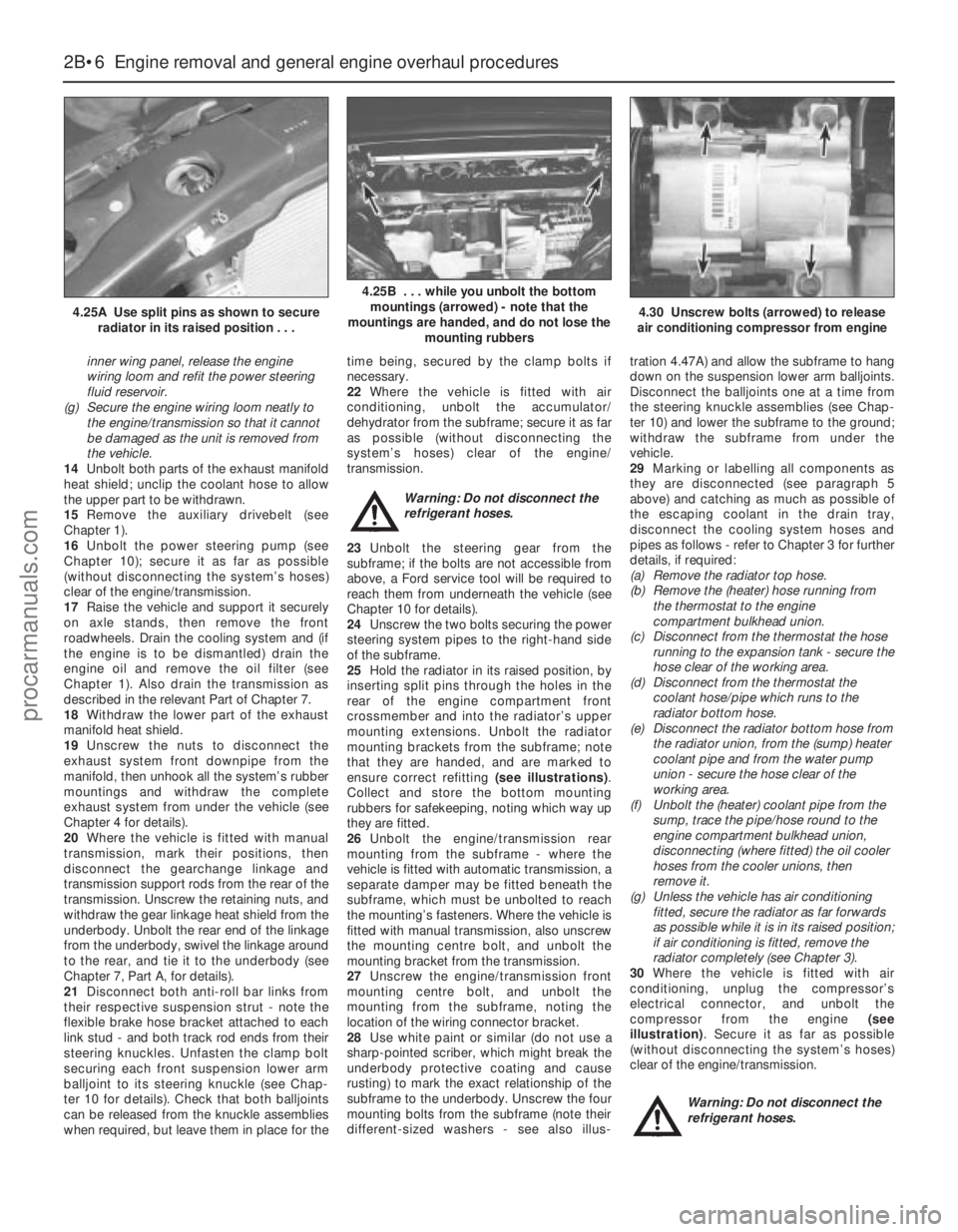
months after delivery), although an important check for a new vehicle,
is not part of the regular maintenance schedule, and is therefore not
mentioned here.
Weekly checks
m mCheck the engine oil level, and top-up if necessary
(Section 3)
m mCheck the brake fluid level, and top-up if necessary
(Section 3). If repeated topping-up is required, check the
system for leaks or damage at the earliest possible
opportunity (Sections 12 and 22)
m mCheck the windscreen/tailgate washer fluid level, and top-
up if necessary (Section 3)
m mCheck the tyre pressures, including the spare (Section 4)
m mVisually check the tyres for excessive tread wear, or
damage (Section 4)
m mCheck the operation of all (exterior and interior) lights and
the horn, wipers and windscreen/tailgate washer system
(Sections 6 and 8). Renew any blown bulbs (Chapter 12),
and clean the lenses of all exterior lights
Monthly checks
m mCheck the coolant level, and top-up if necessary (Sec-
tion 3)
m mCheck the battery electrolyte level, where applicable
(Section 3)
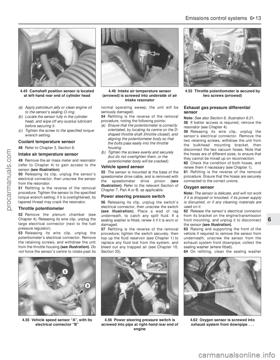
m mCheck the power steering fluid level, and top-up if
necessary (Section 5)
m mVisually check all reservoirs, hoses and pipes for leakage
(Section 12)
m mCheck the operation of the air conditioning system
(Section 14)
m mCheck the operation of the handbrake (Section 23)
m mCheck the aim of the windscreen/tailgate/headlight
washer jets, correcting them if required (Section 6)
m mCheck the condition of the wiper blades, renewing them if
worn or no longer effective - note that the manufacturer
recommends renewing the blades as a safety precaution,
irrespective of their apparent condition, at least once a
year (Section 6)
Every 10 000 miles or 12 months,
whichever occurs first
Note:If the vehicle is used regularly for very short (less than
10 miles), stop/go journeys, the oil and filter should be renewed
between services (ie, every 5000 miles/6 months).
m mCheck the electrical system (Section 8)
m mCheck the battery (Section 9)
m mCheck the seat belts (Section 10)
m mCheck the auxiliary drivebelt (Section 11)
m mCheck for fluid leaks and hose condition (Section 12)
m mCheck the condition of all wiring (Section 13)
m mCheck all air conditioning components (Section 14)
m mChange the engine oil and filter (Section 15)
m mCheck the manual transmission oil level (Section 16)
m mCheck the adjustment of the clutch pedal (Section 17)
m mLubricate the automatic transmission linkage (Section 18)
m mCheck the steering, suspension and wheels (Section 19)
m mCheck the driveshaft gaiters and CV joints (Section 20)
m mCheck the exhaust system (Section 21)
m mCheck the underbody, and all fuel/brake lines (Section 22)
m mCheck the brake system (Section 23)
m mCheck and lubricate the doors and bonnet (Section 24)
m mCheck the security of all roadwheel nuts (Section 25)
m mRoad test (Section 26). Check the level of the automatic
transmission fluid with the engine still hot, after the road
test (Section 7)
Every 20 000 miles or 2 years,
whichever occurs first
Carry out all operations listed above, plus the following:
m mRenew the ventilation system pollen filter (Section 27)
m mRenew the coolant (Sections 2 and 28)
Every 30 000 miles or 3 years,
whichever occurs first
Carry out all operations listed above, plus the following:
m mRenew the air filter element (Section 29). Note that this
task must be carried out at more frequent intervals if the
vehicle is used in dusty or polluted conditions
m mCheck the Positive Crankcase Ventilation (PCV) system,
and clean the filter (Section 30)
m mRenew the spark plugs (Section 31)
Every 60 000 miles
Carry out all operations listed above, plus the following:
m
mRenew the timing belt (Section 32)
m mRenew the fuel filter (Section 33)
Every 3 years
(regardless of mileage)
m mRenew the brake fluid (Section 34)
procarmanuals.com
Page 22 of 279
15Coolant hydrometers are available at
most automotive accessory shops. If the
specific gravity of a sample taken from the
expansion tank (when the engine is switched
off and fully cooled down) is less than that
specified, the coolant mixture strength has
fallen below the minimum. If this is found,
either the coolant strength must be restored
by adding neat antifreeze to Ford’s
specification (if that is what is in the system)
or by draining and flushing the system, then
refilling it with fresh coolant mixture of the
correct ratio (if any other type of antifreeze is
being used).
16When checking the coolant level, always
note its condition; it should be relatively clear.
If it is brown or rust-coloured, the system
should be drained, flushed and refilled. If
antifreeze has been used which does not
meet Ford’s specification, its corrosion
inhibitors will lose their effectiveness with
time; such coolant must be renewed regularly,
even if it appears to be in good condition,
usually at the intervals suggested at the
beginning of Section 2 of this Chapter.
Windscreen/tailgate and
headlight washer fluid
17Fluid for the windscreen/tailgate washer
system (and where applicable the headlight
washer system) is stored in a plastic reservoir,
which is located at the right front corner of the
engine compartment. In milder climates, plain
water can be used to top-up the reservoir, but
the reservoir should be kept no more than
two-thirds full, to allow for expansion should
the water freeze. In colder climates, the use of
a specially-formulated windscreen washer
fluid, available at your dealer or any car
accessory shop, will help lower the freezing
point of the fluid (see illustration). Do notuse
regular (engine) antifreeze - it will damage the
vehicle’s paintwork.
Battery electrolyte
18On models not equipped with a sealed
battery (see Section 9), check the electrolyte
level of all six battery cells. The level must be
approximately 10 mm above the plates; this
may be shown by maximum and minimum
level lines marked on the battery’s casing (seeillustration). If the level is low, use a coin to
release the filler/vent cap, and add distilled
water. Install and securely retighten the cap.
Caution: Overfilling the cells may
cause electrolyte to spill over
during periods of heavy charging,
causing corrosion or damage.
Refer also to the warning at the beginning
of Section 9.
Brake fluid
19The brake fluid reservoir is located on the
top of the brake master cylinder, which is
attached to the front of the vacuum servo unit.
The “MAX” and “MIN” marks are indicated on
the side of the translucent reservoir, and the
fluid level should be maintained between
these marks at all times (see illustration).
20The brake fluid inside the reservoir is
readily visible. With the vehicle on level
ground, the level should normally be on or just
below the “MAX” mark.
21Progressive wear of the brake pads and
brake shoe linings causes the level of the
brake fluid to gradually fall; however, when
the brake pads are renewed, the original level
of the fluid is restored. It is not therefore
necessary to top-up the level to compensate
for this minimal drop, but the level must never
be allowed to fall below the minimum mark.
22If topping-up is necessary, first wipe the
area around the filler cap with a clean rag
before removing the cap. When adding fluid,
pour it carefully into the reservoir, to avoid
spilling it on surrounding painted surfaces
(see illustration). Be sure to use only the
specified hydraulic fluid (see “Lubricants,
fluids and capacities”at the start of this
Chapter) since mixing different types of fluid
can cause damage to the system.
Warning: Brake hydraulic fluid
can harm your eyes and damage
painted surfaces, so use extreme
caution when handling and
pouring it. Wash off spills immediately with
plenty of water. Do not use fluid that has
been standing open for some time, as it
absorbs moisture from the air. Excessmoisture can cause corrosion and a
dangerous loss of braking effectiveness.
23When adding fluid, it is a good idea to
inspect the reservoir for contamination. The
system should be drained and refilled if
deposits, dirt particles or contamination are
seen in the fluid.
24After filling the reservoir to the correct
level, make sure that the cap is refitted
securely, to avoid leaks and the entry of
foreign matter.
25If the reservoir requires repeated
replenishing to maintain the correct level, this
is an indication of an hydraulic leak
somewhere in the system, which should be
investigated immediately.
Power steering fluid
26See Section 5 of this Chapter.
1Periodic inspection of the tyres may spare
you from the inconvenience of being stranded
with a flat tyre. It can also provide you with
vital information regarding possible problems
in the steering and suspension systems
before major damage occurs.
2The original tyres on this vehicle are
equipped with tread wear indicator (TWI)
bands, which will appear when the tread
depth reaches approximately 1.6 mm. Most
tyres have a mark around the tyre at regular
intervals to indicate the location of the tread
4 Tyre and tyre pressure checks
1•8
3.17 Topping-up the windscreen washer
reservoir3.18 On non-sealed batteries, keep the
electrolyte level of all the cells in the
battery between the maximum and
minimum levels (arrowed) - ie, 10 mm
above the plates. Use only distilled water,
and never overfill3.19 Brake fluid reservoir, showing “MAX”
and “MIN” marks
3.22 Topping-up the brake fluid reservoir
Weekly checks
procarmanuals.com
Page 29 of 279
5Check all fluid reservoirs, filler caps, drain
plugs and fittings etc, looking for any signs of
leakage of oil, transmission and/or brake
hydraulic fluid, coolant and power steering
fluid. If the vehicle is regularly parked in the
same place, close inspection of the ground
underneath it will soon show any leaks; ignore
the puddle of water which will be left if the air
conditioning system is in use. As soon as a
leak is detected, its source must be traced
and rectified. Where oil has been leaking for
some time, it is usually necessary to use a
steam cleaner, pressure washer or similar, to
clean away the accumulated dirt, so that the
exact source of the leak can be identified.
Vacuum hoses
6It’s quite common for vacuum hoses,
especially those in the emissions system, to
be colour-coded, or to be identified by
coloured stripes moulded into them. Various
systems require hoses with different wall
thicknesses, collapse resistance and
temperature resistance. When renewing
hoses, be sure the new ones are made of the
same material.
7Often the only effective way to check a
hose is to remove it completely from the
vehicle. If more than one hose is removed, be
sure to label the hoses and fittings to ensure
correct installation.
8When checking vacuum hoses, be sure to
include any plastic T-fittings in the check.
Inspect the fittings for cracks, and check the
hose where it fits over the fitting for distortion,
which could cause leakage.
9A small piece of vacuum hose (quarter-inch
inside diameter) can be used as a
stethoscope to detect vacuum leaks. Hold
one end of the hose to your ear, and probe
around vacuum hoses and fittings, listening
for the “hissing” sound characteristic of a
vacuum leak.
Warning: When probing with the
vacuum hose stethoscope, be
very careful not to come into
contact with moving engine
components such as the auxiliary
drivebelt, radiator electric cooling fan, etc.
Fuel hoses
Warning: There are certain
precautions which must be taken
when inspecting or servicing fuel
system components. Work in a well-
ventilated area, and do not allow open
flames (cigarettes, appliance pilot lights,
etc.) or bare light bulbs near the work
area. Mop up any spills immediately, and
do not store fuel-soaked rags where they
could ignite.
10Check all fuel hoses for deterioration and
chafing. Check especially for cracks in areas
where the hose bends, and also just before
fittings, such as where a hose attaches to the
fuel filter.
11High-quality fuel line, usually identified by
the word “Fluoroelastomer” printed on thehose, should be used for fuel line renewal.
Never, under any circumstances, use
unreinforced vacuum line, clear plastic tubing
or water hose for fuel lines.
12Spring-type clamps are commonly used
on fuel lines. These clamps often lose their
tension over a period of time, and can be
“sprung” during removal. Replace all
spring-type clamps with screw clamps
whenever a hose is replaced.
Metal lines
13Sections of metal piping are often used
for fuel line between the fuel filter and the
engine. Check carefully to be sure the piping
has not been bent or crimped, and that cracks
have not started in the line.
14If a section of metal fuel line must be
renewed, only seamless steel piping should
be used, since copper and aluminium piping
don’t have the strength necessary to
withstand normal engine vibration.
15Check the metal brake lines where they
enter the master cylinder and ABS hydraulic
unit (if used) for cracks in the lines or loose
fittings. Any sign of brake fluid leakage calls
for an immediate and thorough inspection of
the brake system.
1With the vehicle parked on level ground,
apply the handbrake firmly and open the
bonnet. Using an inspection light or a small
electric torch, check all visible wiring within
and beneath the engine compartment.
2What you are looking for is wiring that is
obviously damaged by chafing against sharp
edges, or against moving suspension/
transmission components and/or the auxiliary
drivebelt, by being trapped or crushed
between carelessly-refitted components, or
melted by being forced into contact with the
hot engine castings, coolant pipes, etc. In
almost all cases, damage of this sort is
caused in the first instance by incorrect
routing on reassembly after previous work has
been carried out.
3Depending on the extent of the problem,
damaged wiring may be repaired by rejoining
the break or splicing-in a new length of wire,
using solder to ensure a good connection,
and remaking the insulation with adhesive
insulating tape or heat-shrink tubing, as
appropriate. If the damage is extensive, given
the implications for the vehicle’s future
reliability, the best long-term answer may well
be to renew that entire section of the loom,
however expensive this may appear.
4When the actual damage has been
repaired, ensure that the wiring loom is re-
routed correctly, so that it is clear of other
components, and not stretched or kinked, and
is secured out of harm’s way using the plastic
clips, guides and ties provided.
5Check all electrical connectors, ensuringthat they are clean, securely fastened, and
that each is locked by its plastic tabs or wire
clip, as appropriate. If any connector shows
external signs of corrosion (accumulations of
white or green deposits, or streaks of “rust”),
or if any is thought to be dirty, it must be
unplugged and cleaned using electrical
contact cleaner. If the connector pins are
severely corroded, the connector must be
renewed; note that this may mean the renewal
of that entire section of the loom - see your
local Ford dealer for details.
6If the cleaner completely removes the
corrosion to leave the connector in a
satisfactory condition, it would be wise to
pack the connector with a suitable material
which will exclude dirt and moisture,
preventing the corrosion from occurring
again; a Ford dealer may be able to
recommend a suitable product.
7Check the condition of the battery
connections - remake the connections or
renew the leads if a fault is found (see Chap-
ter 5). Use the same techniques to ensure that
all earth points in the engine compartment
provide good electrical contact through clean,
metal-to-metal joints, and that all are securely
fastened. (In addition to the earth connection
at the engine lifting eye, and that from the
transmission to the body/battery, there are
one or two earth points behind each headlight
assembly, and one below the power steering
fluid reservoir.)
8Refer to Section 31 for details of spark plug
(HT) lead checks.
Warning: The air conditioning
system is under high pressure.
Do not loosen any fittings or
remove any components until
after the system has been discharged. Air
conditioning refrigerant must be properly
discharged into an approved type of
container, at a dealer service department
or an automotive air conditioning repair
facility capable of handling R134a
refrigerant. Always wear eye protection
when disconnecting air conditioning
system fittings.
1The following maintenance checks should
be performed on a regular basis, to ensure
that the air conditioner continues to operate at
peak efficiency:
(a) Check the auxiliary drivebelt. If it’s worn
or deteriorated, renew it (see Section 11).
(b) Check the system hoses. Look for cracks,
bubbles, hard spots and deterioration.
Inspect the hoses and all fittings for oil
bubbles and seepage. If there’s any
evidence of wear, damage or leaks, renew
the hose(s).
(c) Inspect the condenser fins for leaves,
insects and other debris. Use a “fin
14 Air conditioning system
check
13 Engine compartment wiring
check
1•15
1
Every 10 000 miles
procarmanuals.com
Page 72 of 279
inner wing panel, release the engine
wiring loom and refit the power steering
fluid reservoir.
(g) Secure the engine wiring loom neatly to
the engine/transmission so that it cannot
be damaged as the unit is removed from
the vehicle.
14Unbolt both parts of the exhaust manifold
heat shield; unclip the coolant hose to allow
the upper part to be withdrawn.
15Remove the auxiliary drivebelt (see
Chapter 1).
16Unbolt the power steering pump (see
Chapter 10); secure it as far as possible
(without disconnecting the system’s hoses)
clear of the engine/transmission.
17Raise the vehicle and support it securely
on axle stands, then remove the front
roadwheels. Drain the cooling system and (if
the engine is to be dismantled) drain the
engine oil and remove the oil filter (see
Chapter 1). Also drain the transmission as
described in the relevant Part of Chapter 7.
18Withdraw the lower part of the exhaust
manifold heat shield.
19Unscrew the nuts to disconnect the
exhaust system front downpipe from the
manifold, then unhook all the system’s rubber
mountings and withdraw the complete
exhaust system from under the vehicle (see
Chapter 4 for details).
20Where the vehicle is fitted with manual
transmission, mark their positions, then
disconnect the gearchange linkage and
transmission support rods from the rear of the
transmission. Unscrew the retaining nuts, and
withdraw the gear linkage heat shield from the
underbody. Unbolt the rear end of the linkage
from the underbody, swivel the linkage around
to the rear, and tie it to the underbody (see
Chapter 7, Part A, for details).
21Disconnect both anti-roll bar links from
their respective suspension strut - note the
flexible brake hose bracket attached to each
link stud - and both track rod ends from their
steering knuckles. Unfasten the clamp bolt
securing each front suspension lower arm
balljoint to its steering knuckle (see Chap-
ter 10 for details). Check that both balljoints
can be released from the knuckle assemblies
when required, but leave them in place for thetime being, secured by the clamp bolts if
necessary.
22Where the vehicle is fitted with air
conditioning, unbolt the accumulator/
dehydrator from the subframe; secure it as far
as possible (without disconnecting the
system’s hoses) clear of the engine/
transmission.
Warning: Do not disconnect the
refrigerant hoses.
23Unbolt the steering gear from the
subframe; if the bolts are not accessible from
above, a Ford service tool will be required to
reach them from underneath the vehicle (see
Chapter 10 for details).
24Unscrew the two bolts securing the power
steering system pipes to the right-hand side
of the subframe.
25Hold the radiator in its raised position, by
inserting split pins through the holes in the
rear of the engine compartment front
crossmember and into the radiator’s upper
mounting extensions. Unbolt the radiator
mounting brackets from the subframe; note
that they are handed, and are marked to
ensure correct refitting (see illustrations).
Collect and store the bottom mounting
rubbers for safekeeping, noting which way up
they are fitted.
26Unbolt the engine/transmission rear
mounting from the subframe - where the
vehicle is fitted with automatic transmission, a
separate damper may be fitted beneath the
subframe, which must be unbolted to reach
the mounting’s fasteners. Where the vehicle is
fitted with manual transmission, also unscrew
the mounting centre bolt, and unbolt the
mounting bracket from the transmission.
27Unscrew the engine/transmission front
mounting centre bolt, and unbolt the
mounting from the subframe, noting the
location of the wiring connector bracket.
28Use white paint or similar (do not use a
sharp-pointed scriber, which might break the
underbody protective coating and cause
rusting) to mark the exact relationship of the
subframe to the underbody. Unscrew the four
mounting bolts from the subframe (note their
different-sized washers - see also illus-tration 4.47A) and allow the subframe to hang
down on the suspension lower arm balljoints.
Disconnect the balljoints one at a time from
the steering knuckle assemblies (see Chap-
ter 10) and lower the subframe to the ground;
withdraw the subframe from under the
vehicle.
29Marking or labelling all components as
they are disconnected (see paragraph 5
above) and catching as much as possible of
the escaping coolant in the drain tray,
disconnect the cooling system hoses and
pipes as follows - refer to Chapter 3 for further
details, if required:
(a) Remove the radiator top hose.
(b) Remove the (heater) hose running from
the thermostat to the engine
compartment bulkhead union.
(c) Disconnect from the thermostat the hose
running to the expansion tank - secure the
hose clear of the working area.
(d) Disconnect from the thermostat the
coolant hose/pipe which runs to the
radiator bottom hose.
(e) Disconnect the radiator bottom hose from
the radiator union, from the (sump) heater
coolant pipe and from the water pump
union - secure the hose clear of the
working area.
(f) Unbolt the (heater) coolant pipe from the
sump, trace the pipe/hose round to the
engine compartment bulkhead union,
disconnecting (where fitted) the oil cooler
hoses from the cooler unions, then
remove it.
(g) Unless the vehicle has air conditioning
fitted, secure the radiator as far forwards
as possible while it is in its raised position;
if air conditioning is fitted, remove the
radiator completely (see Chapter 3).
30Where the vehicle is fitted with air
conditioning, unplug the compressor’s
electrical connector, and unbolt the
compressor from the engine (see
illustration). Secure it as far as possible
(without disconnecting the system’s hoses)
clear of the engine/transmission.
Warning: Do not disconnect the
refrigerant hoses.
2B•6 Engine removal and general engine overhaul procedures
4.25A Use split pins as shown to secure
radiator in its raised position . . .
4.25B . . . while you unbolt the bottom
mountings (arrowed) - note that the
mountings are handed, and do not lose the
mounting rubbers
4.30 Unscrew bolts (arrowed) to release
air conditioning compressor from engine
procarmanuals.com
Page 147 of 279
(a) Apply petroleum jelly or clean engine oil
to the sensor’s sealing O-ring.
(b) Locate the sensor fully in the cylinder
head, and wipe off any surplus lubricant
before securing it.
(c) Tighten the screw to the specified torque
wrench setting.
Coolant temperature sensor
48Refer to Chapter 3, Section 6.
Intake air temperature sensor
49Remove the air mass meter and resonator
(refer to Chapter 4) to gain access to the
sensor (see illustration).
50Releasing its clip, unplug the sensor’s
electrical connector, then unscrew the sensor
from the resonator.
51Refitting is the reverse of the removal
procedure. Tighten the sensor to the specified
torque wrench setting; if it is overtightened, its
tapered thread may crack the resonator.
Throttle potentiometer
52Remove the plenum chamber (see
Chapter 4). Releasing its wire clip, unplug the
large electrical connector (next to the fuel
pressure regulator).
53Releasing its wire clip, unplug the
potentiometer’s electrical connector. Remove
the retaining screws, and withdraw the unit
from the throttle housing (see illustration). Do
notforce the sensor’s centre to rotate past itsnormal operating sweep; the unit will be
seriously damaged.
54Refitting is the reverse of the removal
procedure, noting the following points:
(a) Ensure that the potentiometer is correctly
orientated, by locating its centre on the D-
shaped throttle shaft (throttle closed), and
aligning the potentiometer body so that
the bolts pass easily into the throttle
housing.
(b) Tighten the screws evenly and securely
(but do not overtighten them, or the
potentiometer body will be cracked).
Vehicle speed sensor
55The sensor is mounted at the base of the
speedometer drive cable, and is removed with
the speedometer drive pinion (see
illustration). Refer to the relevant Section of
Chapter 7, Part A or B, as applicable.
Power steering pressure switch
56Releasing its clip, unplug the switch’s
electrical connector, then unscrew the switch
(see illustration). Place a wad of rag
underneath, to catch any spilt fluid. If a
sealing washer is fitted, renew it if it is worn or
damaged.
57Refitting is the reverse of the removal
procedure; tighten the switch securely, then
top-up the fluid reservoir (see Chapter 1) to
replace any fluid lost from the system, and
bleed out any trapped air (see Chapter 10,
Section 33).
Exhaust gas pressure differential
sensor
Note:See also Section 6, illustration 6.21.
58If better access is required, remove the
resonator (see Chapter 4).
59Releasing its wire clip, unplug the
sensor’s electrical connector. Remove the
two retaining screws, withdraw the unit from
the bulkhead mounting bracket, then
disconnect the two vacuum hoses. Note that
the hoses are of different sizes, to ensure that
they cannot be mixed up on reconnection.
60Check the condition of both hoses, and
renew them if necessary (see Chapter 1).
61Refitting is the reverse of the removal
procedure. Ensure that the hoses are securely
connected to the correct unions.
Oxygen sensor
Note:The sensor is delicate, and will not work
if it is dropped or knocked, if its power supply
is disrupted, or if any cleaning materials are
used on it.
62Release the sensor’s electrical connector
from its bracket on the engine/transmission
front mounting, and unplug it to disconnect
the sensor (see illustration).
63Raising and supporting the front of the
vehicle if required to remove the sensor from
underneath, unscrew the sensor from the
exhaust system front downpipe; collect the
sealing washer (where fitted).
64On refitting, clean the sealing washer
Emissions control systems 6•13
6
4.56 Power steering pressure switch is
screwed into pipe at right-hand rear end of
engine4.62 Oxygen sensor is screwed into
exhaust system front downpipe . . .
4.49 Intake air temperature sensor
(arrowed) is screwed into underside of air
intake resonator4.53 Throttle potentiometer is secured by
two screws (arrowed)
4.55 Vehicle speed sensor “A”, with its
electrical connector “B”
4.45 Camshaft position sensor is located
at left-hand rear end of cylinder head
procarmanuals.com
Page 219 of 279
the specified mileage (or time) since the last
service has been reached.
4To reset the service interval system and
turn off the light, a switch inside the glovebox
must be depressed for a minimum of 4
seconds with the ignition switched on. This
should be carried out by a Ford dealer if the
vehicle is still in the warranty period.
Component renewal
5The following paragraphs describe brief
removal procedures for the auxiliary warning
system components. Disconnect the battery
negative (earth) lead before commencing
work (refer to Chapter 5, Section 1). Refitting
procedures are a reversal of removal.
Display warning bulb
6Remove the control assembly.
7Prise off the cover, and pull out the relevant
bulb and bulbholder.
Low air temperature warning sender
unit
8Remove the front bumper.
9Unclip the sender unit and disconnect the
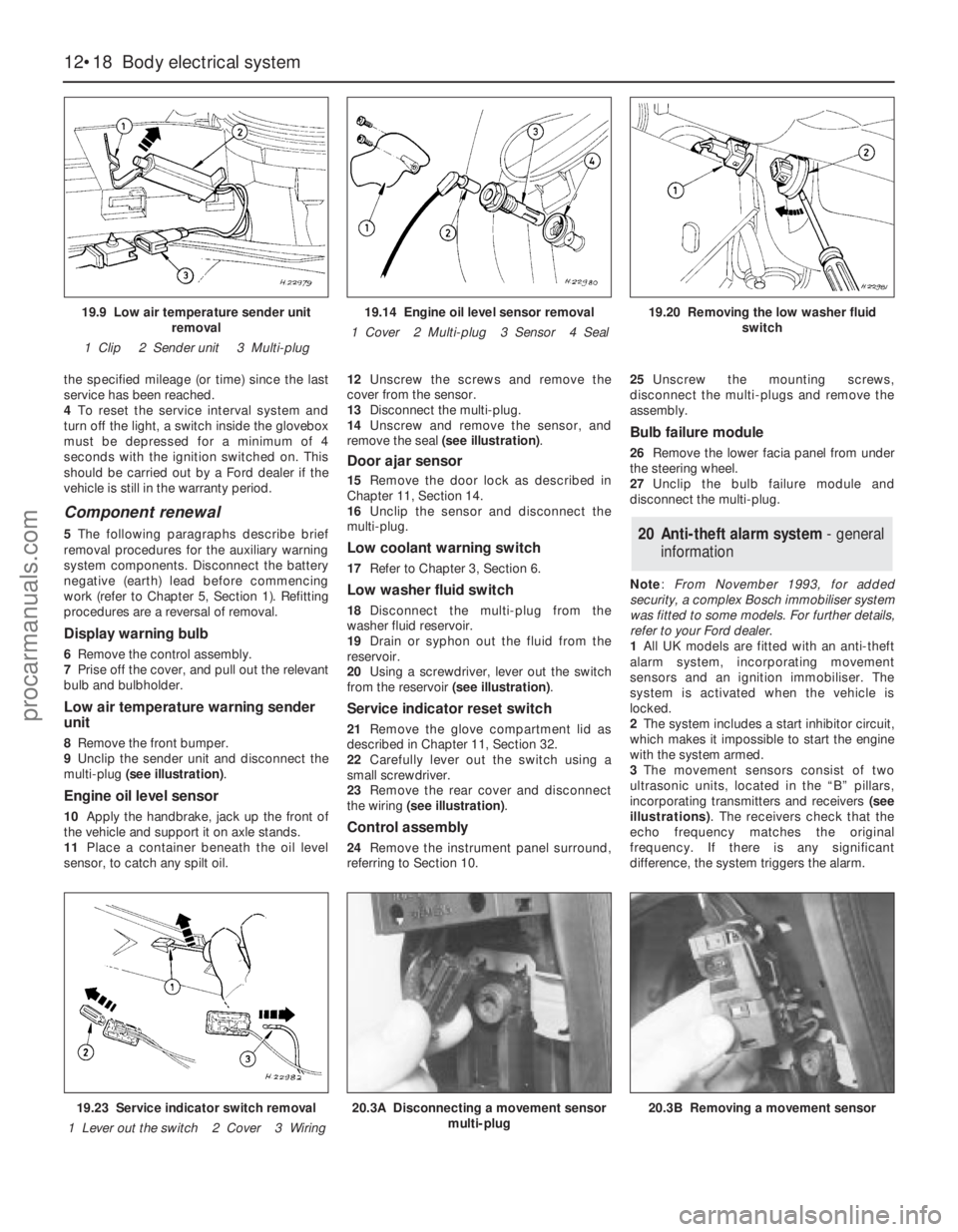
multi-plug (see illustration).
Engine oil level sensor
10Apply the handbrake, jack up the front of
the vehicle and support it on axle stands.
11Place a container beneath the oil level
sensor, to catch any spilt oil.12Unscrew the screws and remove the
cover from the sensor.
13Disconnect the multi-plug.
14Unscrew and remove the sensor, and
remove the seal (see illustration).
Door ajar sensor
15Remove the door lock as described in
Chapter 11, Section 14.
16Unclip the sensor and disconnect the
multi-plug.
Low coolant warning switch
17Refer to Chapter 3, Section 6.
Low washer fluid switch
18Disconnect the multi-plug from the
washer fluid reservoir.
19Drain or syphon out the fluid from the
reservoir.
20Using a screwdriver, lever out the switch
from the reservoir (see illustration).
Service indicator reset switch
21Remove the glove compartment lid as
described in Chapter 11, Section 32.
22Carefully lever out the switch using a
small screwdriver.
23Remove the rear cover and disconnect
the wiring (see illustration).
Control assembly
24Remove the instrument panel surround,
referring to Section 10.25Unscrew the mounting screws,
disconnect the multi-plugs and remove the
assembly.
Bulb failure module
26Remove the lower facia panel from under
the steering wheel.
27Unclip the bulb failure module and
disconnect the multi-plug.
Note: From November 1993, for added
security, a complex Bosch immobiliser system
was fitted to some models. For further details,
refer to your Ford dealer.
1All UK models are fitted with an anti-theft
alarm system, incorporating movement
sensors and an ignition immobiliser. The
system is activated when the vehicle is
locked.
2The system includes a start inhibitor circuit,
which makes it impossible to start the engine
with the system armed.
3The movement sensors consist of two
ultrasonic units, located in the “B” pillars,
incorporating transmitters and receivers (see
illustrations). The receivers check that the
echo frequency matches the original
frequency. If there is any significant
difference, the system triggers the alarm.
20 Anti-theft alarm system- general
information
12•18 Body electrical system
19.9 Low air temperature sender unit
removal
1 Clip 2 Sender unit 3 Multi-plug19.14 Engine oil level sensor removal
1 Cover 2 Multi-plug 3 Sensor 4 Seal19.20 Removing the low washer fluid
switch
19.23 Service indicator switch removal
1 Lever out the switch 2 Cover 3 Wiring20.3A Disconnecting a movement sensor
multi-plug20.3B Removing a movement sensor
procarmanuals.com