1993 FORD MONDEO jacking
[x] Cancel search: jackingPage 2 of 279
LIVING WITH YOUR FORD MONDEO
IntroductionPage 0•4
Safety First!Page 0•5
General dimensions and weights Page0•6
MOT Test Checks
Checks carried out from the driver’s seat Page0•7
Checks carried out with the vehicle on the ground Page0•8
Checks carried out with the vehicle raised Page0•9
Checks carried out on your vehicle’s exhaust emission system Page0•10
Roadside Repairs
Jacking, towing and wheel changing Page0•11
Booster battery (jump) starting Page0•12
Identifying leaksPage0•13
Conversion factorsPage0•14
Routine Maintenance
Routine maintenance and servicing Page1•1
Lubricants, fluids and capacities Page1•2
Maintenance schedule Page1•3
Weekly checks Page1•6
Every 10 000 miles or 12 months Page1•11
Every 20 000 miles or 2 years Page1•20
Every 30 000 miles or 3 years Page1•22
Every 60 000 miles Page1•26
Every 3 yearsPage1•26
Contents
procarmanuals.com
Page 5 of 279
Working on your car can be dangerous.
This page shows just some of the potential
risks and hazards, with the aim of creating a
safety-conscious attitude.
General hazards
Scalding
• Don’t remove the radiator or expansion
tank cap while the engine is hot.
• Engine oil, automatic transmission fluid or
power steering fluid may also be dangerously
hot if the engine has recently been running.
Burning
• Beware of burns from the exhaust system
and from any part of the engine. Brake discs
and drums can also be extremely hot
immediately after use.
Crushing
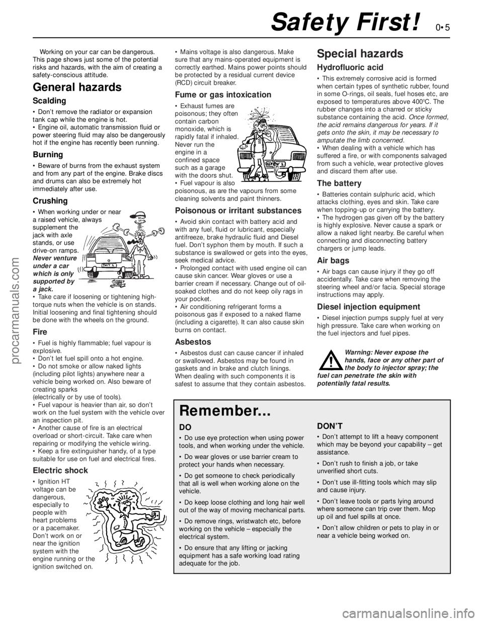
• When working under or near
a raised vehicle, always
supplement the
jack with axle
stands, or use
drive-on ramps.
Never venture
under a car
which is only
supported by
a jack.
• Take care if loosening or tightening high-
torque nuts when the vehicle is on stands.
Initial loosening and final tightening should
be done with the wheels on the ground.
Fire
• Fuel is highly flammable; fuel vapour is
explosive.
• Don’t let fuel spill onto a hot engine.
• Do not smoke or allow naked lights
(including pilot lights) anywhere near a
vehicle being worked on. Also beware of
creating sparks
(electrically or by use of tools).
• Fuel vapour is heavier than air, so don’t
work on the fuel system with the vehicle over
an inspection pit.
• Another cause of fire is an electrical
overload or short-circuit. Take care when
repairing or modifying the vehicle wiring.
• Keep a fire extinguisher handy, of a type
suitable for use on fuel and electrical fires.
Electric shock
• Ignition HT
voltage can be
dangerous,
especially to
people with
heart problems
or a pacemaker.
Don’t work on or
near the ignition
system with the
engine running or the
ignition switched on.• Mains voltage is also dangerous. Make
sure that any mains-operated equipment is
correctly earthed. Mains power points should
be protected by a residual current device
(RCD) circuit breaker.
Fume or gas intoxication
• Exhaust fumes are
poisonous; they often
contain carbon
monoxide, which is
rapidly fatal if inhaled.
Never run the
engine in a
confined space
such as a garage
with the doors shut.
• Fuel vapour is also
poisonous, as are the vapours from some
cleaning solvents and paint thinners.
Poisonous or irritant substances
• Avoid skin contact with battery acid and
with any fuel, fluid or lubricant, especially
antifreeze, brake hydraulic fluid and Diesel
fuel. Don’t syphon them by mouth. If such a
substance is swallowed or gets into the eyes,
seek medical advice.
• Prolonged contact with used engine oil can
cause skin cancer. Wear gloves or use a
barrier cream if necessary. Change out of oil-
soaked clothes and do not keep oily rags in
your pocket.
• Air conditioning refrigerant forms a
poisonous gas if exposed to a naked flame
(including a cigarette). It can also cause skin
burns on contact.
Asbestos
• Asbestos dust can cause cancer if inhaled
or swallowed. Asbestos may be found in
gaskets and in brake and clutch linings.
When dealing with such components it is
safest to assume that they contain asbestos.
Special hazards
Hydrofluoric acid
• This extremely corrosive acid is formed
when certain types of synthetic rubber, found
in some O-rings, oil seals, fuel hoses etc, are
exposed to temperatures above 400
0C. The
rubber changes into a charred or sticky
substance containing the acid. Once formed,
the acid remains dangerous for years. If it
gets onto the skin, it may be necessary to
amputate the limb concerned.
• When dealing with a vehicle which has
suffered a fire, or with components salvaged
from such a vehicle, wear protective gloves
and discard them after use.
The battery
• Batteries contain sulphuric acid, which
attacks clothing, eyes and skin. Take care
when topping-up or carrying the battery.
• The hydrogen gas given off by the battery
is highly explosive. Never cause a spark or
allow a naked light nearby. Be careful when
connecting and disconnecting battery
chargers or jump leads.
Air bags
• Air bags can cause injury if they go off
accidentally. Take care when removing the
steering wheel and/or facia. Special storage
instructions may apply.
Diesel injection equipment
• Diesel injection pumps supply fuel at very
high pressure. Take care when working on
the fuel injectors and fuel pipes.
Warning: Never expose the
hands, face or any other part of
the body to injector spray; the
fuel can penetrate the skin with
potentially fatal results.
Remember...
DO
• Do use eye protection when using power
tools, and when working under the vehicle.
• Do wear gloves or use barrier cream to
protect your hands when necessary.
• Do get someone to check periodically
that all is well when working alone on the
vehicle.
• Do keep loose clothing and long hair well
out of the way of moving mechanical parts.
• Do remove rings, wristwatch etc, before
working on the vehicle – especially the
electrical system.
• Do ensure that any lifting or jacking
equipment has a safe working load rating
adequate for the job.
A few tips
DON’T
• Don’t attempt to lift a heavy component
which may be beyond your capability – get
assistance.
• Don’t rush to finish a job, or take
unverified short cuts.
• Don’t use ill-fitting tools which may slip
and cause injury.
• Don’t leave tools or parts lying around
where someone can trip over them. Mop
up oil and fuel spills at once.
• Don’t allow children or pets to play in or
near a vehicle being worked on.
0•5Safety First!
procarmanuals.com
Page 11 of 279
0•11Roadside Repairs
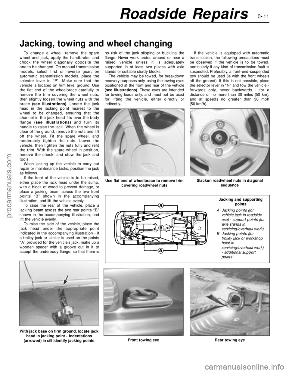
To change a wheel, remove the spare
wheel and jack, apply the handbrake, and
chock the wheel diagonally opposite the
one to be changed. On manual transmission
models, select first or reverse gear; on
automatic transmission models, place the
selector lever in “P”. Make sure that the
vehicle is located on firm level ground. Use
the flat end of the wheelbrace carefully to
remove the trim covering the wheel nuts,
then slightly loosen the wheel nuts with the
brace (see illustrations). Locate the jack
head in the jacking point nearest to the
wheel to be changed, ensuring that the
channel in the jack head fits over the body
flange (see illustrations)and turn its
handle to raise the jack. When the wheel is
clear of the ground, remove the nuts and lift
off the wheel. Fit the spare wheel, and
moderately tighten the nuts. Lower the
vehicle, then tighten the nuts fully and refit
the trim. With the spare wheel in position,
remove the chock, and stow the jack and
tools.
When jacking up the vehicle to carry out
repair or maintenance tasks, position the jack
as follows.
If the front of the vehicle is to be raised,
either place the jack head under the sump,
with a block of wood to prevent damage, or
place a jacking beam across the two front
points “B” shown in the accompanying
illustration, and lift the vehicle evenly.
To raise the rear of the vehicle, place a
jacking beam across the two rear points “B”
shown in the accompanying illustration, and
lift the vehicle evenly.
To raise the side of the vehicle, place the
jack head under the appropriate point
indicated in the accompanying illustration - if
a trolley jack or similar is used on the points
“A” provided for the vehicle’s jack, make up a
wooden spacer with a groove cut in it to
accept the underbody flange, so that there isno risk of the jack slipping or buckling the
flange. Never work under, around or near a
raised vehicle unless it is adequately
supported in at least two places with axle
stands or suitable sturdy blocks.
The vehicle may be towed, for breakdown
recovery purposes only, using the towing eyes
positioned at the front and rear of the vehicle
(see illustrations). These eyes are intended
for towing loads only, and must not be used
for lifting the vehicle, either directly or
indirectly.If the vehicle is equipped with automatic
transmission, the following precautions must
be observed if the vehicle is to be towed,
particularly if any kind of transmission fault is
suspected. Preferably, a front-end-suspended
tow should be used (ie with the front wheels
off the ground). If this is not possible, place
the selector lever in “N” and tow the vehicle -
forwards only, never backwards - for a
distance of no more than 30 miles (50 km),
and at speeds no greater than 30 mph
(50 km/h).
Jacking, towing and wheel changing
Front towing eyeRear towing eye
Use flat end of wheelbrace to remove trim
covering roadwheel nutsSlacken roadwheel nuts in diagonal
sequence
With jack base on firm ground, locate jack
head in jacking point - indentations
(arrowed) in sill identify jacking points
Jacking and supporting
points
A Jacking points (for
vehicle jack in roadside
use) - support points (for
axle stands in
servicing/overhaul work)
B Jacking points (for
trolley jack or workshop
hoist in
servicing/overhaul work)
- additional support
points
procarmanuals.com
Page 40 of 279
1•26Every 60 000 miles
Every 60 000 miles
Refer to Chapter 2, Part A.
Warning: Petrol is extremely
flammable, so extra precautions
must be taken when working on
any part of the fuel system. Do not smoke,
or allow open flames or bare light bulbs,
near the work area. Also, do not work in a
garage if a gas appliance with a pilot light is
present. While performing any work on the
fuel system, wear safety glasses, and have
a suitable (Class B) fire extinguisher on
hand. If you spill any fuel on your skin, rinse
it off immediately with soap and water.
1The fuel filter is located at the front right-
hand corner of the fuel tank, just forward of
the vehicle’s right-hand rear jacking point. The
filter performs a vital role in keeping dirt and
other foreign matter out of the fuel system,
and so must be renewed at regular intervals,or whenever you have reason to suspect that
it may be clogged. It is always unpleasant
working under a vehicle - pressure-washing or
hosing clean the underbody in the filter’s
vicinity will make working conditions more
tolerable, and will reduce the risk of getting
dirt into the fuel system.
2Relieve any residual pressure in the system
by removing the fuel pump fuse (No 14) and
starting the engine; allow the engine to idle until
it dies. Turn the engine over once or twice on
the starter, to ensure that all pressure is
released, then switch off the ignition.
Warning: This procedure will
merely relieve the pressure
necessary for the engine to run -
remember that fuel will still be present in
the system components, and take
precautions before disconnecting them.
3Noting the comments made in Section 1 of
Chapter 5, disconnect the battery earth terminal.
4Jack up the rear right-hand side of the
vehicle, and support it securely on an axle stand.
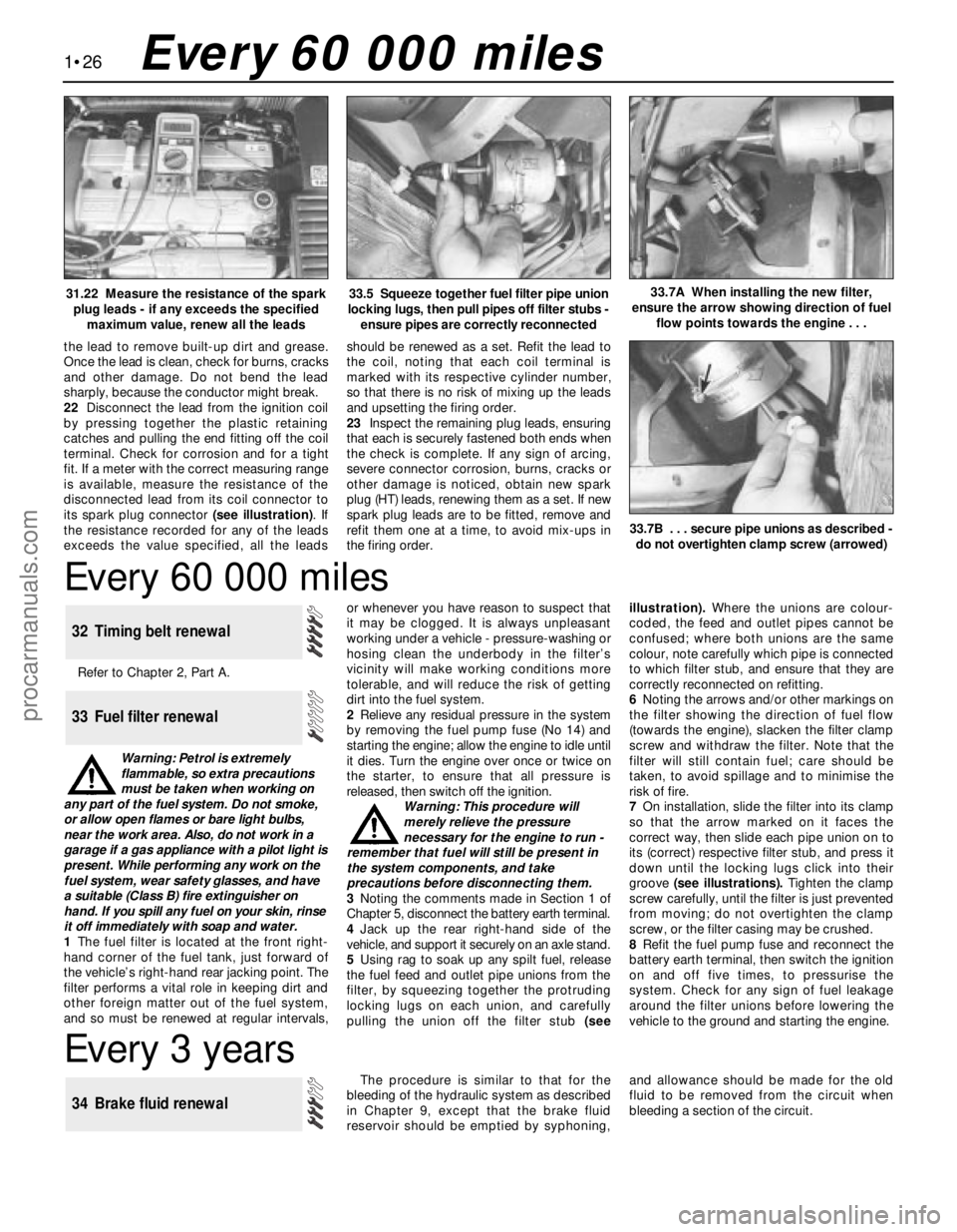
5Using rag to soak up any spilt fuel, release
the fuel feed and outlet pipe unions from the
filter, by squeezing together the protruding
locking lugs on each union, and carefully
pulling the union off the filter stub (seeillustration). Where the unions are colour-
coded, the feed and outlet pipes cannot be
confused; where both unions are the same
colour, note carefully which pipe is connected
to which filter stub, and ensure that they are
correctly reconnected on refitting.
6Noting the arrows and/or other markings on
the filter showing the direction of fuel flow
(towards the engine), slacken the filter clamp
screw and withdraw the filter. Note that the
filter will still contain fuel; care should be
taken, to avoid spillage and to minimise the
risk of fire.
7On installation, slide the filter into its clamp
so that the arrow marked on it faces the
correct way, then slide each pipe union on to
its (correct) respective filter stub, and press it
down until the locking lugs click into their
groove (see illustrations). Tighten the clamp
screw carefully, until the filter is just prevented
from moving; do not overtighten the clamp
screw, or the filter casing may be crushed.
8Refit the fuel pump fuse and reconnect the
battery earth terminal, then switch the ignition
on and off five times, to pressurise the
system. Check for any sign of fuel leakage
around the filter unions before lowering the
vehicle to the ground and starting the engine.
33 Fuel filter renewal
32 Timing belt renewal
33.5 Squeeze together fuel filter pipe union
locking lugs, then pull pipes off filter stubs -
ensure pipes are correctly reconnected33.7A When installing the new filter,
ensure the arrow showing direction of fuel
flow points towards the engine . . .
Every 3 years
The procedure is similar to that for the
bleeding of the hydraulic system as described
in Chapter 9, except that the brake fluid
reservoir should be emptied by syphoning,and allowance should be made for the old
fluid to be removed from the circuit when
bleeding a section of the circuit.
34 Brake fluid renewal
31.22 Measure the resistance of the spark
plug leads - if any exceeds the specified
maximum value, renew all the leads
the lead to remove built-up dirt and grease.
Once the lead is clean, check for burns, cracks
and other damage. Do not bend the lead
sharply, because the conductor might break.
22Disconnect the lead from the ignition coil
by pressing together the plastic retaining
catches and pulling the end fitting off the coil
terminal. Check for corrosion and for a tight
fit. If a meter with the correct measuring range
is available, measure the resistance of the
disconnected lead from its coil connector to
its spark plug connector (see illustration). If
the resistance recorded for any of the leads
exceeds the value specified, all the leadsshould be renewed as a set. Refit the lead to
the coil, noting that each coil terminal is
marked with its respective cylinder number,
so that there is no risk of mixing up the leads
and upsetting the firing order.
23Inspect the remaining plug leads, ensuring
that each is securely fastened both ends when
the check is complete. If any sign of arcing,
severe connector corrosion, burns, cracks or
other damage is noticed, obtain new spark
plug (HT) leads, renewing them as a set. If new
spark plug leads are to be fitted, remove and
refit them one at a time, to avoid mix-ups in
the firing order.
33.7B . . . secure pipe unions as described -
do not overtighten clamp screw (arrowed)
procarmanuals.com
Page 159 of 279
Since most of the procedures dealt with in
this Chapter involve jacking up the vehicle
and working underneath it, a good pair of axle
stands will be needed. A hydraulic trolley jack
is the preferred type of jack to lift the vehicle,
and it can also be used to support certain
components during removal and refitting
operations.
Warning: Never, under any
circumstances, rely on a jack to
support the vehicle while working
beneath it. When jacking up the vehicle, do
not lift or support it beneath the front or
rear subframes.
Removal
1Apply the handbrake. Remove the wheel
cover from the relevant front wheel, and
loosen (but do not remove) the driveshaft/hub
nut. This nut is very tight.
2Loosen the front wheel nuts, jack up the
front of the vehicle and support it on axle
stands. Remove the front wheel.
3Extract the split pin from the track rod end
balljoint nut. Unscrew the nut, and detach the
rod from the arm on the steering knuckle
using a conventional balljoint removal tool.
Take care not to damage the balljoint seal.
4Remove the ABS sensor (when fitted) as
described in Chapter 9.
5Remove the brake caliper and brake disc as
described in Chapter 9, but do not disconnect
the flexible hose from the caliper. Suspend
the caliper from a suitable point under the
wheel arch, taking care not to strain the hose.
6Unscrew and remove the driveshaft/hub
nut. Note that the nut is of special laminated
design, and should only be re-used a
maximum of 5 times. (It is a good idea to file a
small notch on the nut every time it is
removed.) Obtain a new nut if necessary.
7Note which way round the lower arm
balljoint clamp bolt is fitted, then unscrew and
remove it from the knuckle assembly. Lever
the balljoint down from the knuckle; if it is
tight, prise the clamp open using a large flat-
bladed tool. Take care not to damage the
balljoint seal during the separation procedure.
8Unscrew and remove the pinch-bolt
securing the steering knuckle assembly to the
front suspension strut, noting which way
round it is fitted. Prise open the clamp using a
wedge-shaped tool, and release the knuckle
from the strut. If necessary, tap the knuckle
downwards with a soft-headed mallet to
separate the two components. Support the
knuckle on an axle stand.
9Pull the steering knuckle and hub assembly
from the driveshaft splines. If it is tight,
connect a universal puller to the hub flange,
and withdraw it from the driveshaft. When the
driveshaft is free, support it on an axle stand,
or suspend it from a suitable point under thewheel arch, making sure that the inner
constant velocity joint is not turned through
more than 18°. (Damage may occur if the joint
is turned through too great an angle.)
Refitting
10Lift the steering knuckle and hub
assembly onto the driveshaft splines, and
support the assembly on an axle stand.
11Locate the assembly on the front
suspension strut. Insert the pinch-bolt with its
head facing forwards. Fit the nut and tighten it
to the specified torque.
12Refit the lower arm balljoint to the knuckle
assembly, and insert the clamp bolt with its
head facing forwards. Refit the nut and tighten
it to the specified torque.
13Refit the driveshaft/hub nut, and tighten it
moderately at this stage. Final tightening of
the nut is made with the vehicle lowered to the
ground.
14Refit the brake caliper and brake disc as
described in Chapter 9.
15Where fitted, refit the ABS sensor as
described in Chapter 9.
16Reconnect the track rod end balljoint to
the steering arm, and tighten the nut to the
specified torque. Check that the split pin
holes are aligned; if necessary, turn the nut to
the nearest alignment, making sure that the
torque wrench setting is still within the
specified range. Insert a new split pin, and
bend it back to secure.
17Refit the front wheel, and lower the
vehicle to the ground. Tighten the wheel nuts
to the specified torque.
18Tighten the driveshaft/hub nut to the
specified torque, and refit the wheel cover.
Inspection
1The front hub bearings are non-adjustable,
and are supplied already greased.
2To check the bearings for excessive wear,
apply the handbrake, jack up the front of the
vehicle and support it on axle stands.
3Grip the front wheel at top and bottom, and
attempt to rock it. If excessive movement is
noted, it may be that the hub bearings are
worn. Do not confuse wear in the driveshaft
outer joint or front suspension lower arm
balljoint with wear in the bearings. Hub
bearing wear will show up as roughness or
vibration when the wheel is spun; it will also
be noticeable as a rumbling or growling noise
when driving.
Renewal
4Remove the steering knuckle and hub
assembly as described in Section 2.
5The hub must now be removed from the
bearing inner races. It is preferable to use a
press to do this, but it is possible to drive outthe hub using a length of metal tube of
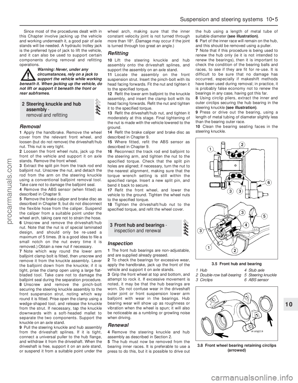
suitable diameter (see illustration).
6Part of the inner race will remain on the hub,
and this should be removed using a puller.
7Note that if this procedure is being used to
renew the hub only (ie it is not intended to
renew the bearings), then it is important to
check the condition of the bearing balls and
races, to see if they are fit for re-use. It is
difficult to be sure that no damage has
occurred, especially if makeshift methods
have been used during removal; in practice, it
is probably false economy not to renew the
bearings in any case, having got this far.
8Using circlip pliers, extract the inner and
outer circlips securing the hub bearing in the
steering knuckle (see illustration).
9Press or drive out the bearing, using a
length of metal tubing of diameter slightly less
than the bearing outer race.
10Clean the bearing seating faces in the
steering knuckle.
3 Front hub and bearings -
inspection and renewal
2 Steering knuckle and hub
assembly -
removal and refitting
Suspension and steering systems 10•5
10
3.5 Front hub and bearing
1 Hub 4 Stub axle
2 Double-row ball-bearing 5 Steering knuckle
3 Circlips 6 ABS sensor
3.8 Front wheel bearing retaining circlips
(arrowed)
procarmanuals.com
Page 277 of 279
REF•18Index
E
Earth fault - 12•4
Economy/Sport mode switch - 12•7
ECU (Electronic Control Unit) - 6•10, 6•11,
6•12
EGR exhaust gas pressure differential
sensor - 6•16
EGR system - 6•15, 6•16
Electric shock - 0•5
Electric windows fault - REF•12
Electrical system - 0•8, 1•11, 1•20
Electrical system fault - REF•12
Electrically-operated windows - 12•7
Electrolyte - 1•8
Electronic control system - 4•9, 6•2
Emblems - 11•17
Emission checks - 0•10
Emissions control systems - 6•1
Engine compartment light - 12•11
Engine electrical systems- 5•1et seq
Engine fault finding - REF•7, REF•8, REF•10
Engine management system - 4•8, 4•9
Engine oil - 1•2, 1•6, 1•16
Engine oil level sensor - 12•18
Engine removal and general engine
overhaul procedures- 2B•1et seq
Environmental considerations - REF•4
Evaporative emissions control (EVAP)
system - 6•14
Evaporator - 3•9
Exhaust gas pressure differential sensor -
6•11, 6•12, 6•13
Exhaust Gas Recirculation (EGR) system -
6•15, 6•16
Exhaust manifold - 2A•8
Exhaust system - 0•9, 0•10, 1•18, 4•12,
REF•9
Expansion tank - 3•5, 3•6
FFacia - 11•21, 11•23
Fan(s) - 3•4, 12•11
Fault code read-out - 6•6
Fault finding- REF•6et seq
Fault finding - automatic transmission -
7B•1
Fault finding - electrical system - 12•4
Filling - 11•3
Fire - 0•5
Fluid level checks - 1•6
Flywheel - 2A•24
Foglight - 12•7, 12•9, 12•13
Foglight warning indicator - 12•11
Fuel and exhaust systems- 0•10, 4•1et
seq
Fuel and exhaust system fault finding -
REF•9
Fuel consumption high - REF•9
Fuel cut-off switch - 4•8
Fuel filter - 1•26
Fuel gauge - 4•6
Fuel gauge fault - REF•12
Fuel hoses - 1•15
Fuel injection system - 4•8, 4•9
Fuel injectors - 4•10
Fuel lines - 1•19, 4•2
Fuel odour - REF•9Fuel pressure check - 4•5
Fuel pressure regulator - 4•11
Fuel pump - 4•5, 4•6
Fuel rail - 4•10
Fuel system - 4•2
Fuel tank - 4•7, 4•8
Fume or gas intoxication - 0•5
Fumes from exhaust system - REF•9
Fuses - 12•5
G
Gaiters - 1•18, 8•7, 8•9, 10•21
Gashes in bodywork - 11•3
Gaskets - REF•4
Gear lever - 7A•2
Gear selection problems - REF•9, REF•10
Gearbox oil - 1•2
Gearchange linkage - 7A•2
Gearchange selector shaft - 7A•3
Glossary of technical terms - REF•13
Glovebox - 11•22
Glovebox light - 12•11
Grab handle - 11•20
H
Handbrake - 0•7, 9•16, 12•7
Handles - 11•10, 11•11, 11•12, 11•13,
12•11
Hazard flashers - 12•7, 12•11
HC emissions - 0•10
Headlight - 1•8, 12•7, 12•8, 12•12, 12•13
Heated rear window - 12•8
Heated seat - 12•8
Heated windscreen - 12•8
Heater - 3•2, 3•7, 3•8, 12•11, 12•12
Horn - 12•7, 12•15
Horn fault - REF•12
Hoses - 1•14, 3•2, 9•11
HT leads - 1•24
Hub and bearings - 10•5, 10•9, 10•14
Hydraulic fluid - 1•2
Hydraulic pipes and hoses - 9•11
Hydraulic system - 9•12
Hydraulic tappets - 2A•14
Hydrofluoric acid - 0•5
I
Idle speed - 4•9, 4•11, 6•10
Idle-increase solenoid valve - 4•12
Ignition coil - 5•3
Ignition module - 5•4
Ignition switch - 12•6
Ignition system - 5•3
Ignition timing - 5•4, 6•10
In-car engine repair procedures- 2A•1et
seq
Indicators - 12•7, 12•9, 12•12
Information sensors - 6•10
Inlet manifold - 2A•7
Instrument panel - 12•7, 12•11, 12•14
Instruments - 1•20
Instruments fault - REF•12
Intake air temperature sensor - 6•11, 6•13
Introduction to the Ford Mondeo - 0•4
J
Jacking - 0•11
Joint mating faces - REF•4
Jump starting - 0•12
K
Knuckle - 10•5, 10•10, 10•14
L
Leaks - 0•13, 1•14, REF•9
Light units - 12•12
Lights - 12•7, 12•11
Lights inoperative - REF•12
Locknuts, locktabs and washers - REF•4
Locks - 11•6, 11•10, 11•12, 11•13, 11•15,
11•16, 11•17, 12•6, REF•12
Low air temperature warning sender unit -
12•18
Low coolant warning switch - 12•18
Low washer fluid switch - 12•18
Lower suspension arm - 10•8, 10•9, 10•13,
10•16
Lubrication system - 2A•4
Luggage compartment switch - 12•7
M
Main bearings - 2B•18, 2B•20
Maintenance- Also see Routine
maintenance
Maintenance - bodywork and underframe -
11•2
Maintenance - upholstery and carpets -
11•3
Manifolds - 2A•7, 2A•8
Manual transmission- 1•17, 2A•24, 2B•3,
2B•4, 7A•1et seq
Manual transmission fault finding - REF•9
Manual transmission oil - 1•2
Master cylinder - 9•10
Mirrors - 0•7, 11•14, 12•7
Misfire - REF•7, REF•8
Mixture - 0•10, 4•9
MOT test checks- 0•7et seq
Mountings - 2A•24, 7A•7, 7B•5
N
Number plate light - 12•10, 12•13
O
Oil (transmission) - 1•2
Oil (engine) - 1•2, 1•6, 1•16
Oil cooler - 2A•22
Oil level sensor - 2A•22, 12•18
Oil pressure warning light illuminated -
REF•8
procarmanuals.com