1993 FORD MONDEO interior lights
[x] Cancel search: interior lightsPage 17 of 279
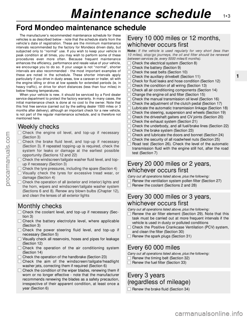
Ford Mondeo maintenance schedule
1•3
1
Maintenance schedule
The manufacturer’s recommended maintenance schedule for these
vehicles is as described below - note that the schedule starts from the
vehicle’s date of registration. These are the minimum maintenance
intervals recommended by the factory for Mondeos driven daily, but
subjected only to “normal” use. If you wish to keep your vehicle in
peak condition at all times, you may wish to perform some of these
procedures even more often. Because frequent maintenance
enhances the efficiency, performance and resale value of your vehicle,
we encourage you to do so. If your usage is not “normal”, shorter
intervals are also recommended - the most important examples of
these are noted in the schedule. These shorter intervals apply
particularly if you drive in dusty areas, tow a caravan or trailer, sit with
the engine idling or drive at low speeds for extended periods (ie, in
heavy traffic), or drive for short distances (less than four miles) in
below-freezing temperatures.
When your vehicle is new, it should be serviced by a Ford dealer
service department to protect the factory warranty. In many cases, the
initial maintenance check is done at no cost to the owner. Note that
this first free service (carried out by the selling dealer 1500 miles or 3
months after delivery), although an important check for a new vehicle,
is not part of the regular maintenance schedule, and is therefore not
mentioned here.
Weekly checks
m mCheck the engine oil level, and top-up if necessary
(Section 3)
m mCheck the brake fluid level, and top-up if necessary
(Section 3). If repeated topping-up is required, check the
system for leaks or damage at the earliest possible
opportunity (Sections 12 and 22)
m mCheck the windscreen/tailgate washer fluid level, and top-
up if necessary (Section 3)
m mCheck the tyre pressures, including the spare (Section 4)
m mVisually check the tyres for excessive tread wear, or
damage (Section 4)
m mCheck the operation of all (exterior and interior) lights and
the horn, wipers and windscreen/tailgate washer system
(Sections 6 and 8). Renew any blown bulbs (Chapter 12),
and clean the lenses of all exterior lights
Monthly checks
m mCheck the coolant level, and top-up if necessary (Sec-
tion 3)
m mCheck the battery electrolyte level, where applicable
(Section 3)
m mCheck the power steering fluid level, and top-up if
necessary (Section 5)
m mVisually check all reservoirs, hoses and pipes for leakage
(Section 12)
m mCheck the operation of the air conditioning system
(Section 14)
m mCheck the operation of the handbrake (Section 23)
m mCheck the aim of the windscreen/tailgate/headlight
washer jets, correcting them if required (Section 6)
m mCheck the condition of the wiper blades, renewing them if
worn or no longer effective - note that the manufacturer
recommends renewing the blades as a safety precaution,
irrespective of their apparent condition, at least once a
year (Section 6)
Every 10 000 miles or 12 months,
whichever occurs first
Note:If the vehicle is used regularly for very short (less than
10 miles), stop/go journeys, the oil and filter should be renewed
between services (ie, every 5000 miles/6 months).
m mCheck the electrical system (Section 8)
m mCheck the battery (Section 9)
m mCheck the seat belts (Section 10)
m mCheck the auxiliary drivebelt (Section 11)
m mCheck for fluid leaks and hose condition (Section 12)
m mCheck the condition of all wiring (Section 13)
m mCheck all air conditioning components (Section 14)
m mChange the engine oil and filter (Section 15)
m mCheck the manual transmission oil level (Section 16)
m mCheck the adjustment of the clutch pedal (Section 17)
m mLubricate the automatic transmission linkage (Section 18)
m mCheck the steering, suspension and wheels (Section 19)
m mCheck the driveshaft gaiters and CV joints (Section 20)
m mCheck the exhaust system (Section 21)
m mCheck the underbody, and all fuel/brake lines (Section 22)
m mCheck the brake system (Section 23)
m mCheck and lubricate the doors and bonnet (Section 24)
m mCheck the security of all roadwheel nuts (Section 25)
m mRoad test (Section 26). Check the level of the automatic
transmission fluid with the engine still hot, after the road
test (Section 7)
Every 20 000 miles or 2 years,
whichever occurs first
Carry out all operations listed above, plus the following:
m mRenew the ventilation system pollen filter (Section 27)
m mRenew the coolant (Sections 2 and 28)
Every 30 000 miles or 3 years,
whichever occurs first
Carry out all operations listed above, plus the following:
m mRenew the air filter element (Section 29). Note that this
task must be carried out at more frequent intervals if the
vehicle is used in dusty or polluted conditions
m mCheck the Positive Crankcase Ventilation (PCV) system,
and clean the filter (Section 30)
m mRenew the spark plugs (Section 31)
Every 60 000 miles
Carry out all operations listed above, plus the following:
m
mRenew the timing belt (Section 32)
m mRenew the fuel filter (Section 33)
Every 3 years
(regardless of mileage)
m mRenew the brake fluid (Section 34)
procarmanuals.com
Page 202 of 279
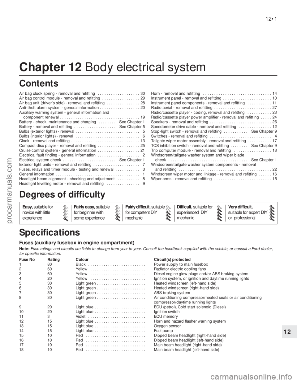
Chapter 12 Body electrical system
Air bag clock spring - removal and refitting . . . . . . . . . . . . . . . . . . . 30
Air bag control module - removal and refitting . . . . . . . . . . . . . . . . . 29
Air bag unit (driver’s side) - removal and refitting . . . . . . . . . . . . . . . 28
Anti-theft alarm system - general information . . . . . . . . . . . . . . . . . . 20
Auxiliary warning system - general information and
component renewal . . . . . . . . . . . . . . . . . . . . . . . . . . . . . . . . . . . . 19
Battery - check, maintenance and charging . . . . . . . . See Chapter 1
Battery - removal and refitting . . . . . . . . . . . . . . . . . . . See Chapter 5
Bulbs (exterior lights) - renewal . . . . . . . . . . . . . . . . . . . . . . . . . . . . . 5
Bulbs (interior lights) - renewal . . . . . . . . . . . . . . . . . . . . . . . . . . . . . 6
Clock - removal and refitting . . . . . . . . . . . . . . . . . . . . . . . . . . . . . . . 13
Compact disc player - removal and refitting . . . . . . . . . . . . . . . . . . . 25
Cruise control system - general information . . . . . . . . . . . . . . . . . . . 21
Electrical fault finding - general information . . . . . . . . . . . . . . . . . . . 2
Electrical system check . . . . . . . . . . . . . . . . . . . . . . . . See Chapter 1
Exterior light units - removal and refitting . . . . . . . . . . . . . . . . . . . . . 7
Fuses, relays and timer module - testing and renewal . . . . . . . . . . . 3
General information . . . . . . . . . . . . . . . . . . . . . . . . . . . . . . . . . . . . . . 1
Headlight beam alignment - checking and adjustment . . . . . . . . . . 8
Headlight levelling motor - removal and refitting . . . . . . . . . . . . . . . 9Horn - removal and refitting . . . . . . . . . . . . . . . . . . . . . . . . . . . . . . . 14
Instrument panel - removal and refitting . . . . . . . . . . . . . . . . . . . . . . 10
Instrument panel components - removal and refitting . . . . . . . . . . . 11
Radio aerial - removal and refitting . . . . . . . . . . . . . . . . . . . . . . . . . . 27
Radio/cassette player - coding, removal and refitting . . . . . . . . . . . 23
Radio/cassette player power amplifier - removal and refitting . . . . . 24
Speakers - removal and refitting . . . . . . . . . . . . . . . . . . . . . . . . . . . . 26
Speedometer drive cable - removal and refitting . . . . . . . . . . . . . . . 12
Stop-light switch - removal and refitting . . . . . . . . . . . See Chapter 9
Switches - removal and refitting . . . . . . . . . . . . . . . . . . . . . . . . . . . . 4
Tailgate wiper motor assembly - removal and refitting . . . . . . . . . . . 17
TCS inhibition switch - removal and refitting . . . . . . . . See Chapter 9
Trip computer module - removal and refitting . . . . . . . . . . . . . . . . . 18
Windscreen/tailgate washer system and wiper blade
check . . . . . . . . . . . . . . . . . . . . . . . . . . . . . . . . . . . . See Chapter 1
Windscreen/tailgate washer system components - removal
and refitting . . . . . . . . . . . . . . . . . . . . . . . . . . . . . . . . . . . . . . . . . . 22
Windscreen wiper motor and linkage - removal and refitting . . . . . . 16
Wiper arms - removal and refitting . . . . . . . . . . . . . . . . . . . . . . . . . . 15
Fuses (auxiliary fusebox in engine compartment)
Note:Fuse ratings and circuits are liable to change from year to year. Consult the handbook supplied with the vehicle, or consult a Ford dealer,
for specific information.
Fuse No Rating Colour Circuit(s) protected
1 80 Black . . . . . . . . . . . . . . . . . . . . . . . . . . Power supply to main fusebox
2 60 Yellow . . . . . . . . . . . . . . . . . . . . . . . . . Radiator electric cooling fans
3 60 Yellow . . . . . . . . . . . . . . . . . . . . . . . . . Diesel engine glow plugs and/or ABS braking system
4 20 Yellow . . . . . . . . . . . . . . . . . . . . . . . . . Ignition system, or ignition and daytime running lights
5 30 Light green . . . . . . . . . . . . . . . . . . . . . . Heated windscreen (left-hand side)
6 30 Light green . . . . . . . . . . . . . . . . . . . . . . Heated windscreen (right-hand side)
7 30 Light green . . . . . . . . . . . . . . . . . . . . . . ABS braking system
8 30 Light green . . . . . . . . . . . . . . . . . . . . . . Air conditioning compressor/heated seats or air conditioning
compressor/daytime running lights
9 20 Light blue . . . . . . . . . . . . . . . . . . . . . . . ECU (petrol), Cold start solenoid (Diesel)
10 20 Light blue . . . . . . . . . . . . . . . . . . . . . . . Ignition switch
11 3 Violet . . . . . . . . . . . . . . . . . . . . . . . . . . ECU memory
12 15 Light blue . . . . . . . . . . . . . . . . . . . . . . . Horn and hazard flasher warning system
13 15 Light blue . . . . . . . . . . . . . . . . . . . . . . . Oxygen sensor
14 15 Light blue . . . . . . . . . . . . . . . . . . . . . . . Fuel pump
15 10 Red . . . . . . . . . . . . . . . . . . . . . . . . . . . Dipped beam headlight (right-hand side)
16 10 Red . . . . . . . . . . . . . . . . . . . . . . . . . . . Dipped beam headlight (left-hand side)
17 10 Red . . . . . . . . . . . . . . . . . . . . . . . . . . . Main beam headlight (right-hand side)
18 10 Red . . . . . . . . . . . . . . . . . . . . . . . . . . . Main beam headlight (left-hand side)
12•1
Easy,suitable for
novice with little
experienceFairly easy,suitable
for beginner with
some experienceFairly difficult,suitable
for competent DIY
mechanicDifficult,suitable for
experienced DIY
mechanicVery difficult,
suitable for expert DIY
or professional
Degrees of difficulty
Specifications Contents
12
procarmanuals.com
Page 203 of 279
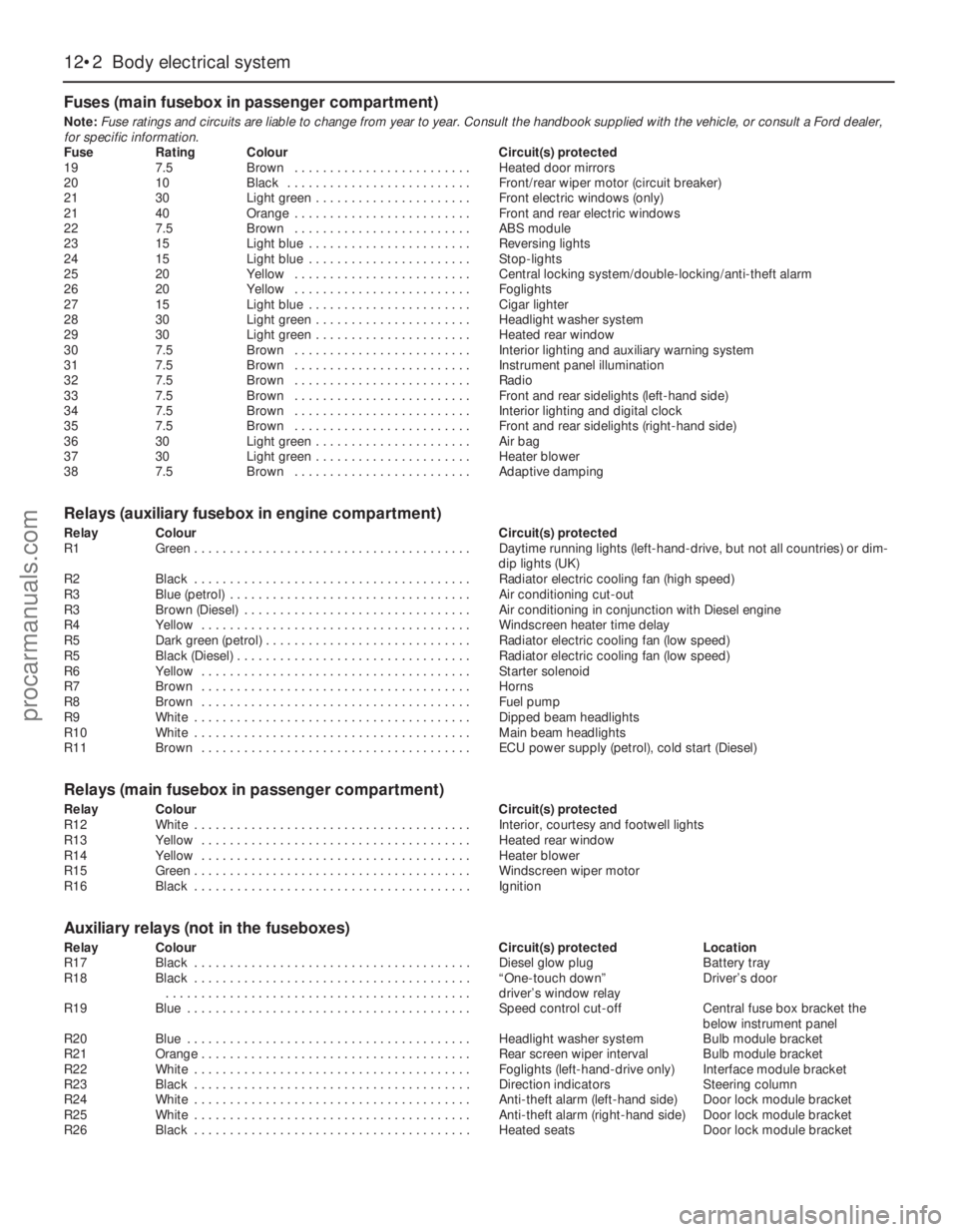
Fuses (main fusebox in passenger compartment)
Note:Fuse ratings and circuits are liable to change from year to year. Consult the handbook supplied with the vehicle, or consult a Ford dealer,
for specific information.
Fuse Rating Colour Circuit(s) protected
19 7.5 Brown . . . . . . . . . . . . . . . . . . . . . . . . . Heated door mirrors
20 10 Black . . . . . . . . . . . . . . . . . . . . . . . . . . Front/rear wiper motor (circuit breaker)
21 30 Light green . . . . . . . . . . . . . . . . . . . . . . Front electric windows (only)
21 40 Orange . . . . . . . . . . . . . . . . . . . . . . . . . Front and rear electric windows
22 7.5 Brown . . . . . . . . . . . . . . . . . . . . . . . . . ABS module
23 15 Light blue . . . . . . . . . . . . . . . . . . . . . . . Reversing lights
24 15 Light blue . . . . . . . . . . . . . . . . . . . . . . . Stop-lights
25 20 Yellow . . . . . . . . . . . . . . . . . . . . . . . . . Central locking system/double-locking/anti-theft alarm
26 20 Yellow . . . . . . . . . . . . . . . . . . . . . . . . . Foglights
27 15 Light blue . . . . . . . . . . . . . . . . . . . . . . . Cigar lighter
28 30 Light green . . . . . . . . . . . . . . . . . . . . . . Headlight washer system
29 30 Light green . . . . . . . . . . . . . . . . . . . . . . Heated rear window
30 7.5 Brown . . . . . . . . . . . . . . . . . . . . . . . . . Interior lighting and auxiliary warning system
31 7.5 Brown . . . . . . . . . . . . . . . . . . . . . . . . . Instrument panel illumination
32 7.5 Brown . . . . . . . . . . . . . . . . . . . . . . . . . Radio
33 7.5 Brown . . . . . . . . . . . . . . . . . . . . . . . . . Front and rear sidelights (left-hand side)
34 7.5 Brown . . . . . . . . . . . . . . . . . . . . . . . . . Interior lighting and digital clock
35 7.5 Brown . . . . . . . . . . . . . . . . . . . . . . . . . Front and rear sidelights (right-hand side)
36 30 Light green . . . . . . . . . . . . . . . . . . . . . . Air bag
37 30 Light green . . . . . . . . . . . . . . . . . . . . . . Heater blower
38 7.5 Brown . . . . . . . . . . . . . . . . . . . . . . . . . Adaptive damping
Relays (auxiliary fusebox in engine compartment)
Relay Colour Circuit(s) protected
R1 Green . . . . . . . . . . . . . . . . . . . . . . . . . . . . . . . . . . . . . . . Daytime running lights (left-hand-drive, but not all countries) or dim-
dip lights (UK)
R2 Black . . . . . . . . . . . . . . . . . . . . . . . . . . . . . . . . . . . . . . . Radiator electric cooling fan (high speed)
R3 Blue (petrol) . . . . . . . . . . . . . . . . . . . . . . . . . . . . . . . . . . Air conditioning cut-out
R3 Brown (Diesel) . . . . . . . . . . . . . . . . . . . . . . . . . . . . . . . . Air conditioning in conjunction with Diesel engine
R4 Yellow . . . . . . . . . . . . . . . . . . . . . . . . . . . . . . . . . . . . . . Windscreen heater time delay
R5 Dark green (petrol) . . . . . . . . . . . . . . . . . . . . . . . . . . . . . Radiator electric cooling fan (low speed)
R5 Black (Diesel) . . . . . . . . . . . . . . . . . . . . . . . . . . . . . . . . . Radiator electric cooling fan (low speed)
R6 Yellow . . . . . . . . . . . . . . . . . . . . . . . . . . . . . . . . . . . . . . Starter solenoid
R7 Brown . . . . . . . . . . . . . . . . . . . . . . . . . . . . . . . . . . . . . . Horns
R8 Brown . . . . . . . . . . . . . . . . . . . . . . . . . . . . . . . . . . . . . . Fuel pump
R9 White . . . . . . . . . . . . . . . . . . . . . . . . . . . . . . . . . . . . . . . Dipped beam headlights
R10 White . . . . . . . . . . . . . . . . . . . . . . . . . . . . . . . . . . . . . . . Main beam headlights
R11 Brown . . . . . . . . . . . . . . . . . . . . . . . . . . . . . . . . . . . . . . ECU power supply (petrol), cold start (Diesel)
Relays (main fusebox in passenger compartment)
Relay Colour Circuit(s) protected
R12 White . . . . . . . . . . . . . . . . . . . . . . . . . . . . . . . . . . . . . . . Interior, courtesy and footwell lights
R13 Yellow . . . . . . . . . . . . . . . . . . . . . . . . . . . . . . . . . . . . . . Heated rear window
R14 Yellow . . . . . . . . . . . . . . . . . . . . . . . . . . . . . . . . . . . . . . Heater blower
R15 Green . . . . . . . . . . . . . . . . . . . . . . . . . . . . . . . . . . . . . . . Windscreen wiper motor
R16 Black . . . . . . . . . . . . . . . . . . . . . . . . . . . . . . . . . . . . . . . Ignition
Auxiliary relays (not in the fuseboxes)
Relay Colour Circuit(s) protected Location
R17 Black . . . . . . . . . . . . . . . . . . . . . . . . . . . . . . . . . . . . . . . Diesel glow plug Battery tray
R18 Black . . . . . . . . . . . . . . . . . . . . . . . . . . . . . . . . . . . . . . . “One-touch down” Driver’s door
. . . . . . . . . . . . . . . . . . . . . . . . . . . . . . . . . . . . . . . . . . . driver’s window relay
R19 Blue . . . . . . . . . . . . . . . . . . . . . . . . . . . . . . . . . . . . . . . . Speed control cut-off Central fuse box bracket the
below instrument panel
R20 Blue . . . . . . . . . . . . . . . . . . . . . . . . . . . . . . . . . . . . . . . . Headlight washer system Bulb module bracket
R21 Orange . . . . . . . . . . . . . . . . . . . . . . . . . . . . . . . . . . . . . . Rear screen wiper interval Bulb module bracket
R22 White . . . . . . . . . . . . . . . . . . . . . . . . . . . . . . . . . . . . . . . Foglights (left-hand-drive only) Interface module bracket
R23 Black . . . . . . . . . . . . . . . . . . . . . . . . . . . . . . . . . . . . . . . Direction indicators Steering column
R24 White . . . . . . . . . . . . . . . . . . . . . . . . . . . . . . . . . . . . . . . Anti-theft alarm (left-hand side) Door lock module bracket
R25 White . . . . . . . . . . . . . . . . . . . . . . . . . . . . . . . . . . . . . . . Anti-theft alarm (right-hand side) Door lock module bracket
R26 Black . . . . . . . . . . . . . . . . . . . . . . . . . . . . . . . . . . . . . . . Heated seats Door lock module bracket
12•2 Body electrical system
procarmanuals.com
Page 204 of 279
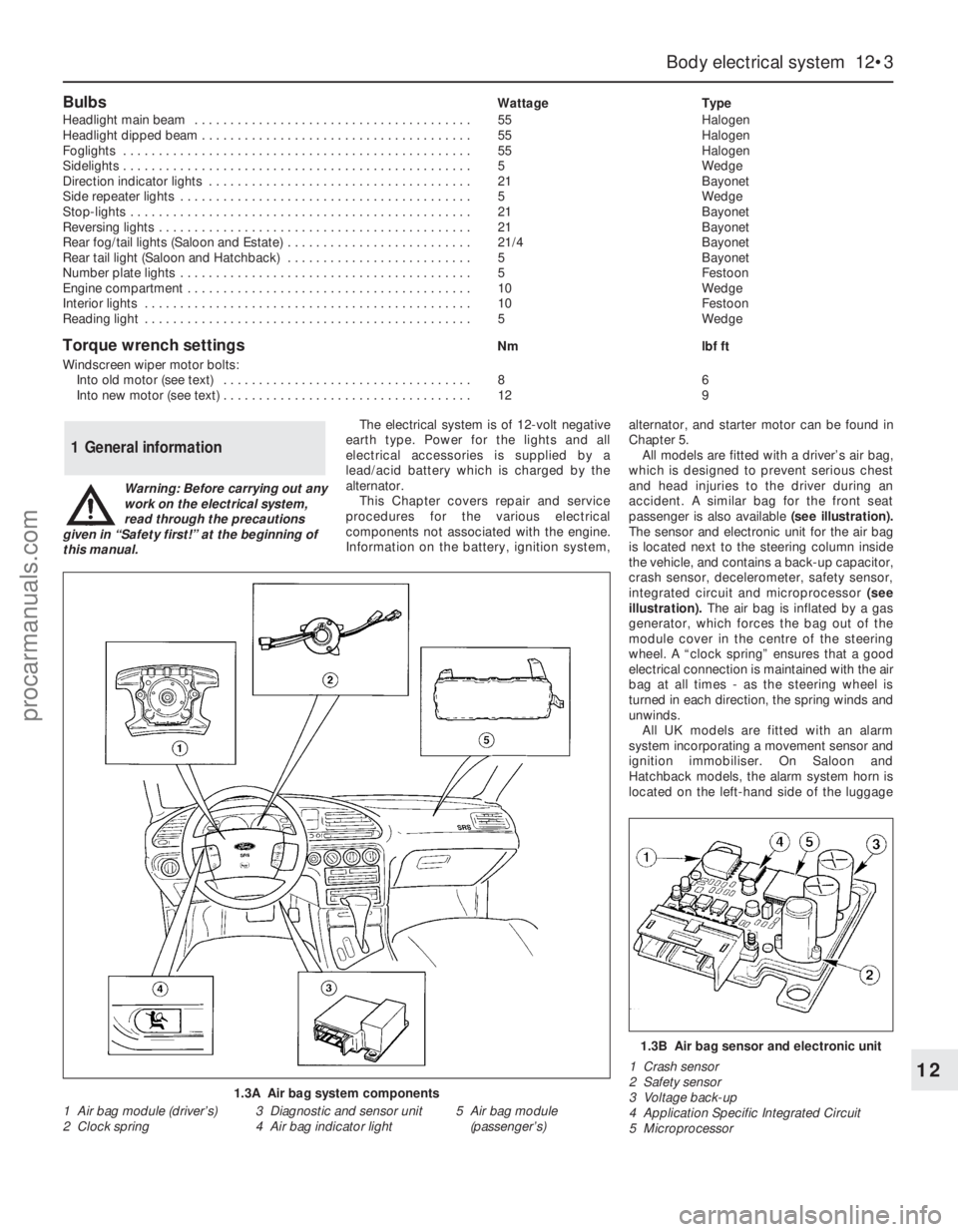
BulbsWattage Type
Headlight main beam . . . . . . . . . . . . . . . . . . . . . . . . . . . . . . . . . . . . . . . 55 Halogen
Headlight dipped beam . . . . . . . . . . . . . . . . . . . . . . . . . . . . . . . . . . . . . . 55 Halogen
Foglights . . . . . . . . . . . . . . . . . . . . . . . . . . . . . . . . . . . . . . . . . . . . . . . . . 55 Halogen
Sidelights . . . . . . . . . . . . . . . . . . . . . . . . . . . . . . . . . . . . . . . . . . . . . . . . . 5 Wedge
Direction indicator lights . . . . . . . . . . . . . . . . . . . . . . . . . . . . . . . . . . . . . 21 Bayonet
Side repeater lights . . . . . . . . . . . . . . . . . . . . . . . . . . . . . . . . . . . . . . . . . 5 Wedge
Stop-lights . . . . . . . . . . . . . . . . . . . . . . . . . . . . . . . . . . . . . . . . . . . . . . . . 21 Bayonet
Reversing lights . . . . . . . . . . . . . . . . . . . . . . . . . . . . . . . . . . . . . . . . . . . . 21 Bayonet
Rear fog/tail lights (Saloon and Estate) . . . . . . . . . . . . . . . . . . . . . . . . . . 21/4 Bayonet
Rear tail light (Saloon and Hatchback) . . . . . . . . . . . . . . . . . . . . . . . . . . 5 Bayonet
Number plate lights . . . . . . . . . . . . . . . . . . . . . . . . . . . . . . . . . . . . . . . . . 5 Festoon
Engine compartment . . . . . . . . . . . . . . . . . . . . . . . . . . . . . . . . . . . . . . . . 10 Wedge
Interior lights . . . . . . . . . . . . . . . . . . . . . . . . . . . . . . . . . . . . . . . . . . . . . . 10 Festoon
Reading light . . . . . . . . . . . . . . . . . . . . . . . . . . . . . . . . . . . . . . . . . . . . . . 5 Wedge
Torque wrench settingsNm lbf ft
Windscreen wiper motor bolts:
Into old motor (see text) . . . . . . . . . . . . . . . . . . . . . . . . . . . . . . . . . . . 8 6
Into new motor (see text) . . . . . . . . . . . . . . . . . . . . . . . . . . . . . . . . . . . 12 9
Body electrical system 12•3
12
Warning: Before carrying out any
work on the electrical system,
read through the precautions
given in “Safety first!” at the beginning of
this manual.The electrical system is of 12-volt negative
earth type. Power for the lights and all
electrical accessories is supplied by a
lead/acid battery which is charged by the
alternator.
This Chapter covers repair and service
procedures for the various electrical
components not associated with the engine.
Information on the battery, ignition system,alternator, and starter motor can be found in
Chapter 5.
All models are fitted with a driver’s air bag,
which is designed to prevent serious chest
and head injuries to the driver during an
accident. A similar bag for the front seat
passenger is also available (see illustration).
The sensor and electronic unit for the air bag
is located next to the steering column inside
the vehicle, and contains a back-up capacitor,
crash sensor, decelerometer, safety sensor,
integrated circuit and microprocessor (see
illustration). The air bag is inflated by a gas
generator, which forces the bag out of the
module cover in the centre of the steering
wheel. A “clock spring” ensures that a good
electrical connection is maintained with the air
bag at all times - as the steering wheel is
turned in each direction, the spring winds and
unwinds.
All UK models are fitted with an alarm
system incorporating a movement sensor and
ignition immobiliser. On Saloon and
Hatchback models, the alarm system horn is
located on the left-hand side of the luggage
1 General information
1.3A Air bag system components
1 Air bag module (driver’s)
2 Clock spring3 Diagnostic and sensor unit
4 Air bag indicator light5 Air bag module
(passenger’s)
1.3B Air bag sensor and electronic unit
1 Crash sensor
2 Safety sensor
3 Voltage back-up
4 Application Specific Integrated Circuit
5 Microprocessor
procarmanuals.com
Page 206 of 279
remade, prevent the onset of corrosion in the
future by applying a coat of petroleum jelly or
silicone-based grease, or by spraying on (at
regular intervals) a proprietary ignition sealer
such as Holts Damp Start, or a water-
dispersant lubricant such as Holts Wet Start.
Note:It is important to note that the ignition
switch and the appropriate electrical circuit
must always be switched off before any of the
fuses (or relays) are removed and renewed. In
the event of the fuse/relay unit having to be
removed, the battery earth lead must be
disconnected. When reconnecting the battery,
reference should be made to Chapter 5.
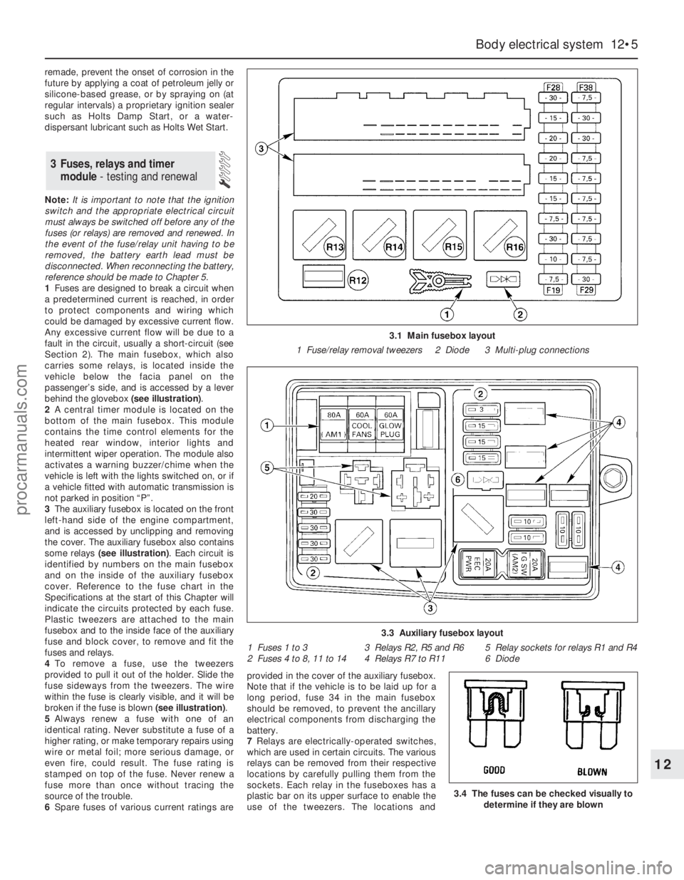
1Fuses are designed to break a circuit when
a predetermined current is reached, in order
to protect components and wiring which
could be damaged by excessive current flow.
Any excessive current flow will be due to a
fault in the circuit, usually a short-circuit (see
Section 2). The main fusebox, which also
carries some relays, is located inside the
vehicle below the facia panel on the
passenger’s side, and is accessed by a lever
behind the glovebox (see illustration).
2A central timer module is located on the
bottom of the main fusebox. This module
contains the time control elements for the
heated rear window, interior lights and
intermittent wiper operation. The module also
activates a warning buzzer/chime when the
vehicle is left with the lights switched on, or if
a vehicle fitted with automatic transmission is
not parked in position “P”.
3The auxiliary fusebox is located on the front
left-hand side of the engine compartment,
and is accessed by unclipping and removing
the cover. The auxiliary fusebox also contains
some relays (see illustration). Each circuit is
identified by numbers on the main fusebox
and on the inside of the auxiliary fusebox
cover. Reference to the fuse chart in the
Specifications at the start of this Chapter will
indicate the circuits protected by each fuse.
Plastic tweezers are attached to the main
fusebox and to the inside face of the auxiliary
fuse and block cover, to remove and fit the
fuses and relays.
4To remove a fuse, use the tweezers
provided to pull it out of the holder. Slide the
fuse sideways from the tweezers. The wire
within the fuse is clearly visible, and it will be
broken if the fuse is blown (see illustration).
5Always renew a fuse with one of an
identical rating. Never substitute a fuse of a
higher rating, or make temporary repairs using
wire or metal foil; more serious damage, or
even fire, could result. The fuse rating is
stamped on top of the fuse. Never renew a
fuse more than once without tracing the
source of the trouble.
6Spare fuses of various current ratings areprovided in the cover of the auxiliary fusebox.
Note that if the vehicle is to be laid up for a
long period, fuse 34 in the main fusebox
should be removed, to prevent the ancillary
electrical components from discharging the
battery.
7Relays are electrically-operated switches,
which are used in certain circuits. The various
relays can be removed from their respective
locations by carefully pulling them from the
sockets. Each relay in the fuseboxes has a
plastic bar on its upper surface to enable the
use of the tweezers. The locations and
3 Fuses, relays and timer
module- testing and renewal
Body electrical system 12•5
12
3.4 The fuses can be checked visually to
determine if they are blown
3.1 Main fusebox layout
1 Fuse/relay removal tweezers 2 Diode 3 Multi-plug connections
3.3 Auxiliary fusebox layout
1 Fuses 1 to 3 3 Relays R2, R5 and R6 5 Relay sockets for relays R1 and R4
2 Fuses 4 to 8, 11 to 14 4 Relays R7 to R11 6 Diode
procarmanuals.com
Page 212 of 279
Engine compartment light
1With the bonnet open, pull the wedge-type
bulb from the bulbholder.
2Fit the new bulb using a reversal of the
removal procedure.
Interior lights
3Switch off the interior light by locating the
switch in its middle position.
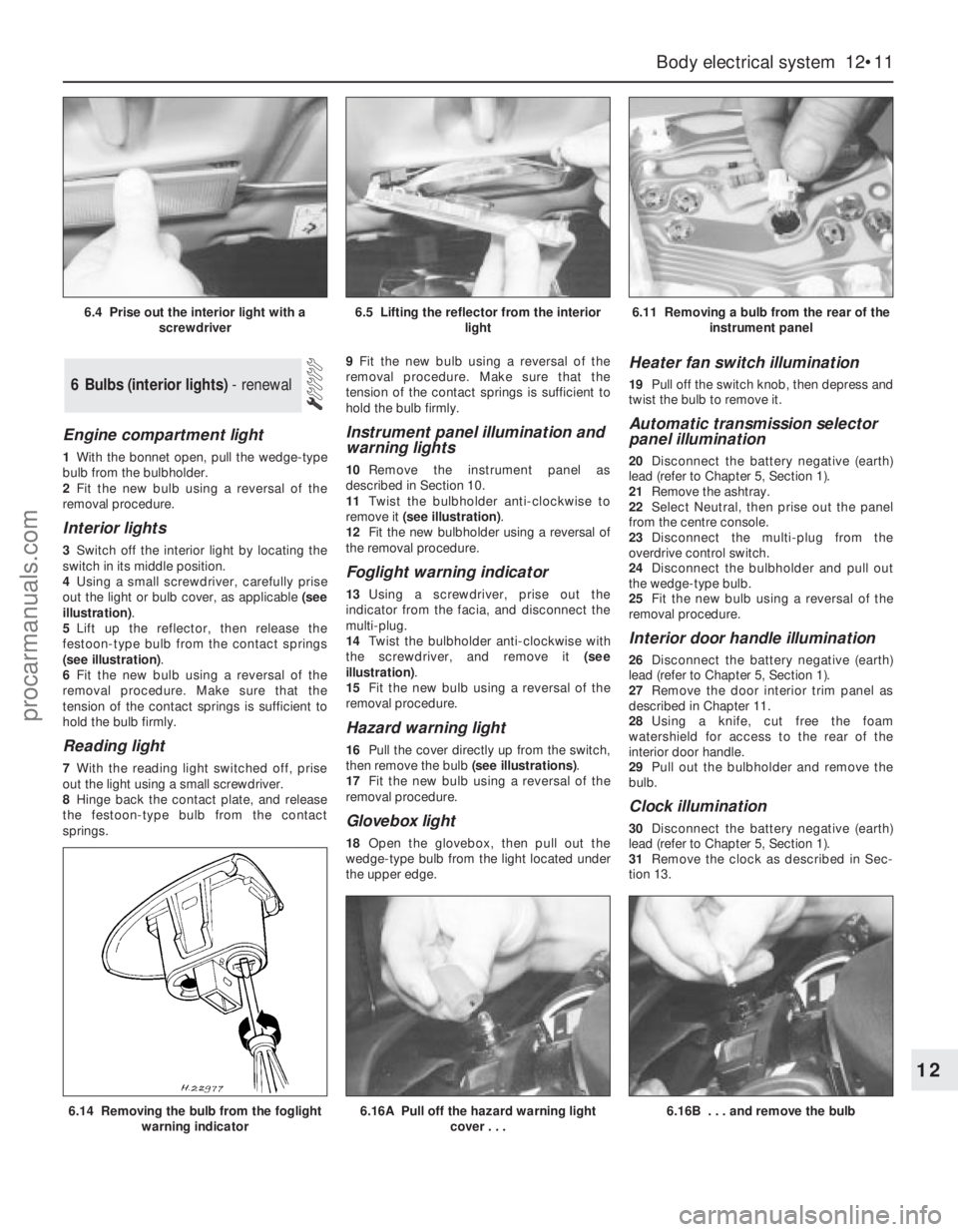
4Using a small screwdriver, carefully prise
out the light or bulb cover, as applicable (see
illustration).
5Lift up the reflector, then release the
festoon-type bulb from the contact springs
(see illustration).
6Fit the new bulb using a reversal of the
removal procedure. Make sure that the
tension of the contact springs is sufficient to
hold the bulb firmly.
Reading light
7With the reading light switched off, prise
out the light using a small screwdriver.
8Hinge back the contact plate, and release
the festoon-type bulb from the contact
springs.9Fit the new bulb using a reversal of the
removal procedure. Make sure that the
tension of the contact springs is sufficient to
hold the bulb firmly.
Instrument panel illumination and
warning lights
10Remove the instrument panel as
described in Section 10.
11Twist the bulbholder anti-clockwise to
remove it (see illustration).
12Fit the new bulbholder using a reversal of
the removal procedure.
Foglight warning indicator
13Using a screwdriver, prise out the
indicator from the facia, and disconnect the
multi-plug.
14Twist the bulbholder anti-clockwise with
the screwdriver, and remove it (see
illustration).
15Fit the new bulb using a reversal of the
removal procedure.
Hazard warning light
16Pull the cover directly up from the switch,
then remove the bulb (see illustrations).
17Fit the new bulb using a reversal of the
removal procedure.
Glovebox light
18Open the glovebox, then pull out the
wedge-type bulb from the light located under
the upper edge.
Heater fan switch illumination
19Pull off the switch knob, then depress and
twist the bulb to remove it.
Automatic transmission selector
panel illumination
20Disconnect the battery negative (earth)
lead (refer to Chapter 5, Section 1).
21Remove the ashtray.
22Select Neutral, then prise out the panel
from the centre console.
23Disconnect the multi-plug from the
overdrive control switch.
24Disconnect the bulbholder and pull out
the wedge-type bulb.
25Fit the new bulb using a reversal of the
removal procedure.
Interior door handle illumination
26Disconnect the battery negative (earth)
lead (refer to Chapter 5, Section 1).
27Remove the door interior trim panel as
described in Chapter 11.
28Using a knife, cut free the foam
watershield for access to the rear of the
interior door handle.
29Pull out the bulbholder and remove the
bulb.
Clock illumination
30Disconnect the battery negative (earth)
lead (refer to Chapter 5, Section 1).
31Remove the clock as described in Sec-
tion 13.
6 Bulbs (interior lights) - renewal
Body electrical system 12•11
12
6.14 Removing the bulb from the foglight
warning indicator6.16A Pull off the hazard warning light
cover . . .6.16B . . . and remove the bulb
6.4 Prise out the interior light with a
screwdriver6.5 Lifting the reflector from the interior
light6.11 Removing a bulb from the rear of the
instrument panel
procarmanuals.com
Page 238 of 279
Wiring diagrams 12•37
12
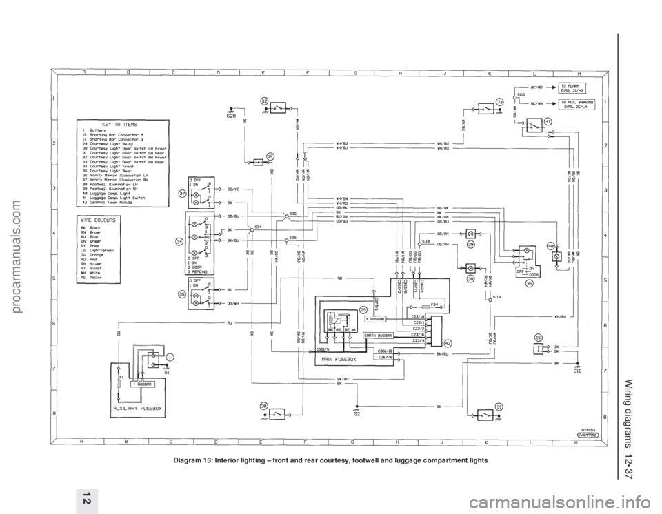
Diagram 13: Interior lighting – front and rear courtesy, footwell and luggage compartment lights
procarmanuals.com
Page 239 of 279
12•38 Wiring diagrams
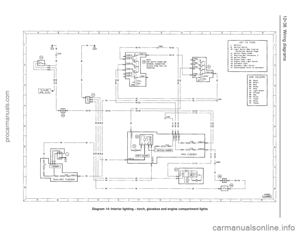
Diagram 14: Interior lighting – torch, glovebox and engine compartment lights
procarmanuals.com