1993 FORD MONDEO bulb
[x] Cancel search: bulbPage 17 of 279
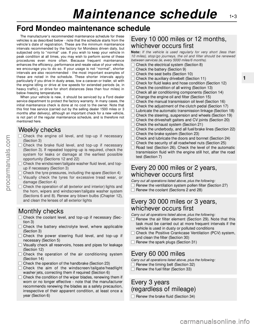
Ford Mondeo maintenance schedule
1•3
1
Maintenance schedule
The manufacturer’s recommended maintenance schedule for these
vehicles is as described below - note that the schedule starts from the
vehicle’s date of registration. These are the minimum maintenance
intervals recommended by the factory for Mondeos driven daily, but
subjected only to “normal” use. If you wish to keep your vehicle in
peak condition at all times, you may wish to perform some of these
procedures even more often. Because frequent maintenance
enhances the efficiency, performance and resale value of your vehicle,
we encourage you to do so. If your usage is not “normal”, shorter
intervals are also recommended - the most important examples of
these are noted in the schedule. These shorter intervals apply
particularly if you drive in dusty areas, tow a caravan or trailer, sit with
the engine idling or drive at low speeds for extended periods (ie, in
heavy traffic), or drive for short distances (less than four miles) in
below-freezing temperatures.
When your vehicle is new, it should be serviced by a Ford dealer
service department to protect the factory warranty. In many cases, the
initial maintenance check is done at no cost to the owner. Note that
this first free service (carried out by the selling dealer 1500 miles or 3
months after delivery), although an important check for a new vehicle,
is not part of the regular maintenance schedule, and is therefore not
mentioned here.
Weekly checks
m mCheck the engine oil level, and top-up if necessary
(Section 3)
m mCheck the brake fluid level, and top-up if necessary
(Section 3). If repeated topping-up is required, check the
system for leaks or damage at the earliest possible
opportunity (Sections 12 and 22)
m mCheck the windscreen/tailgate washer fluid level, and top-
up if necessary (Section 3)
m mCheck the tyre pressures, including the spare (Section 4)
m mVisually check the tyres for excessive tread wear, or
damage (Section 4)
m mCheck the operation of all (exterior and interior) lights and
the horn, wipers and windscreen/tailgate washer system
(Sections 6 and 8). Renew any blown bulbs (Chapter 12),
and clean the lenses of all exterior lights
Monthly checks
m mCheck the coolant level, and top-up if necessary (Sec-
tion 3)
m mCheck the battery electrolyte level, where applicable
(Section 3)
m mCheck the power steering fluid level, and top-up if
necessary (Section 5)
m mVisually check all reservoirs, hoses and pipes for leakage
(Section 12)
m mCheck the operation of the air conditioning system
(Section 14)
m mCheck the operation of the handbrake (Section 23)
m mCheck the aim of the windscreen/tailgate/headlight
washer jets, correcting them if required (Section 6)
m mCheck the condition of the wiper blades, renewing them if
worn or no longer effective - note that the manufacturer
recommends renewing the blades as a safety precaution,
irrespective of their apparent condition, at least once a
year (Section 6)
Every 10 000 miles or 12 months,
whichever occurs first
Note:If the vehicle is used regularly for very short (less than
10 miles), stop/go journeys, the oil and filter should be renewed
between services (ie, every 5000 miles/6 months).
m mCheck the electrical system (Section 8)
m mCheck the battery (Section 9)
m mCheck the seat belts (Section 10)
m mCheck the auxiliary drivebelt (Section 11)
m mCheck for fluid leaks and hose condition (Section 12)
m mCheck the condition of all wiring (Section 13)
m mCheck all air conditioning components (Section 14)
m mChange the engine oil and filter (Section 15)
m mCheck the manual transmission oil level (Section 16)
m mCheck the adjustment of the clutch pedal (Section 17)
m mLubricate the automatic transmission linkage (Section 18)
m mCheck the steering, suspension and wheels (Section 19)
m mCheck the driveshaft gaiters and CV joints (Section 20)
m mCheck the exhaust system (Section 21)
m mCheck the underbody, and all fuel/brake lines (Section 22)
m mCheck the brake system (Section 23)
m mCheck and lubricate the doors and bonnet (Section 24)
m mCheck the security of all roadwheel nuts (Section 25)
m mRoad test (Section 26). Check the level of the automatic
transmission fluid with the engine still hot, after the road
test (Section 7)
Every 20 000 miles or 2 years,
whichever occurs first
Carry out all operations listed above, plus the following:
m mRenew the ventilation system pollen filter (Section 27)
m mRenew the coolant (Sections 2 and 28)
Every 30 000 miles or 3 years,
whichever occurs first
Carry out all operations listed above, plus the following:
m mRenew the air filter element (Section 29). Note that this
task must be carried out at more frequent intervals if the
vehicle is used in dusty or polluted conditions
m mCheck the Positive Crankcase Ventilation (PCV) system,
and clean the filter (Section 30)
m mRenew the spark plugs (Section 31)
Every 60 000 miles
Carry out all operations listed above, plus the following:
m
mRenew the timing belt (Section 32)
m mRenew the fuel filter (Section 33)
Every 3 years
(regardless of mileage)
m mRenew the brake fluid (Section 34)
procarmanuals.com
Page 29 of 279
5Check all fluid reservoirs, filler caps, drain
plugs and fittings etc, looking for any signs of
leakage of oil, transmission and/or brake
hydraulic fluid, coolant and power steering
fluid. If the vehicle is regularly parked in the
same place, close inspection of the ground
underneath it will soon show any leaks; ignore
the puddle of water which will be left if the air
conditioning system is in use. As soon as a
leak is detected, its source must be traced
and rectified. Where oil has been leaking for
some time, it is usually necessary to use a
steam cleaner, pressure washer or similar, to
clean away the accumulated dirt, so that the
exact source of the leak can be identified.
Vacuum hoses
6It’s quite common for vacuum hoses,
especially those in the emissions system, to
be colour-coded, or to be identified by
coloured stripes moulded into them. Various
systems require hoses with different wall
thicknesses, collapse resistance and
temperature resistance. When renewing
hoses, be sure the new ones are made of the
same material.
7Often the only effective way to check a
hose is to remove it completely from the
vehicle. If more than one hose is removed, be
sure to label the hoses and fittings to ensure
correct installation.
8When checking vacuum hoses, be sure to
include any plastic T-fittings in the check.
Inspect the fittings for cracks, and check the
hose where it fits over the fitting for distortion,
which could cause leakage.
9A small piece of vacuum hose (quarter-inch
inside diameter) can be used as a
stethoscope to detect vacuum leaks. Hold
one end of the hose to your ear, and probe
around vacuum hoses and fittings, listening
for the “hissing” sound characteristic of a
vacuum leak.
Warning: When probing with the
vacuum hose stethoscope, be
very careful not to come into
contact with moving engine
components such as the auxiliary
drivebelt, radiator electric cooling fan, etc.
Fuel hoses
Warning: There are certain
precautions which must be taken
when inspecting or servicing fuel
system components. Work in a well-
ventilated area, and do not allow open
flames (cigarettes, appliance pilot lights,
etc.) or bare light bulbs near the work
area. Mop up any spills immediately, and
do not store fuel-soaked rags where they
could ignite.
10Check all fuel hoses for deterioration and
chafing. Check especially for cracks in areas
where the hose bends, and also just before
fittings, such as where a hose attaches to the
fuel filter.
11High-quality fuel line, usually identified by
the word “Fluoroelastomer” printed on thehose, should be used for fuel line renewal.
Never, under any circumstances, use
unreinforced vacuum line, clear plastic tubing
or water hose for fuel lines.
12Spring-type clamps are commonly used
on fuel lines. These clamps often lose their
tension over a period of time, and can be
“sprung” during removal. Replace all
spring-type clamps with screw clamps
whenever a hose is replaced.
Metal lines
13Sections of metal piping are often used
for fuel line between the fuel filter and the
engine. Check carefully to be sure the piping
has not been bent or crimped, and that cracks
have not started in the line.
14If a section of metal fuel line must be
renewed, only seamless steel piping should
be used, since copper and aluminium piping
don’t have the strength necessary to
withstand normal engine vibration.
15Check the metal brake lines where they
enter the master cylinder and ABS hydraulic
unit (if used) for cracks in the lines or loose
fittings. Any sign of brake fluid leakage calls
for an immediate and thorough inspection of
the brake system.
1With the vehicle parked on level ground,
apply the handbrake firmly and open the
bonnet. Using an inspection light or a small
electric torch, check all visible wiring within
and beneath the engine compartment.
2What you are looking for is wiring that is
obviously damaged by chafing against sharp
edges, or against moving suspension/
transmission components and/or the auxiliary
drivebelt, by being trapped or crushed
between carelessly-refitted components, or
melted by being forced into contact with the
hot engine castings, coolant pipes, etc. In
almost all cases, damage of this sort is
caused in the first instance by incorrect
routing on reassembly after previous work has
been carried out.
3Depending on the extent of the problem,
damaged wiring may be repaired by rejoining
the break or splicing-in a new length of wire,
using solder to ensure a good connection,
and remaking the insulation with adhesive
insulating tape or heat-shrink tubing, as
appropriate. If the damage is extensive, given
the implications for the vehicle’s future
reliability, the best long-term answer may well
be to renew that entire section of the loom,
however expensive this may appear.
4When the actual damage has been
repaired, ensure that the wiring loom is re-
routed correctly, so that it is clear of other
components, and not stretched or kinked, and
is secured out of harm’s way using the plastic
clips, guides and ties provided.
5Check all electrical connectors, ensuringthat they are clean, securely fastened, and
that each is locked by its plastic tabs or wire
clip, as appropriate. If any connector shows
external signs of corrosion (accumulations of
white or green deposits, or streaks of “rust”),
or if any is thought to be dirty, it must be
unplugged and cleaned using electrical
contact cleaner. If the connector pins are
severely corroded, the connector must be
renewed; note that this may mean the renewal
of that entire section of the loom - see your
local Ford dealer for details.
6If the cleaner completely removes the
corrosion to leave the connector in a
satisfactory condition, it would be wise to
pack the connector with a suitable material
which will exclude dirt and moisture,
preventing the corrosion from occurring
again; a Ford dealer may be able to
recommend a suitable product.
7Check the condition of the battery
connections - remake the connections or
renew the leads if a fault is found (see Chap-
ter 5). Use the same techniques to ensure that
all earth points in the engine compartment
provide good electrical contact through clean,
metal-to-metal joints, and that all are securely
fastened. (In addition to the earth connection
at the engine lifting eye, and that from the
transmission to the body/battery, there are
one or two earth points behind each headlight
assembly, and one below the power steering
fluid reservoir.)
8Refer to Section 31 for details of spark plug
(HT) lead checks.
Warning: The air conditioning
system is under high pressure.
Do not loosen any fittings or
remove any components until
after the system has been discharged. Air
conditioning refrigerant must be properly
discharged into an approved type of
container, at a dealer service department
or an automotive air conditioning repair
facility capable of handling R134a
refrigerant. Always wear eye protection
when disconnecting air conditioning
system fittings.
1The following maintenance checks should
be performed on a regular basis, to ensure
that the air conditioner continues to operate at
peak efficiency:
(a) Check the auxiliary drivebelt. If it’s worn
or deteriorated, renew it (see Section 11).
(b) Check the system hoses. Look for cracks,
bubbles, hard spots and deterioration.
Inspect the hoses and all fittings for oil
bubbles and seepage. If there’s any
evidence of wear, damage or leaks, renew
the hose(s).
(c) Inspect the condenser fins for leaves,
insects and other debris. Use a “fin
14 Air conditioning system
check
13 Engine compartment wiring
check
1•15
1
Every 10 000 miles
procarmanuals.com
Page 40 of 279
1•26Every 60 000 miles
Every 60 000 miles
Refer to Chapter 2, Part A.
Warning: Petrol is extremely
flammable, so extra precautions
must be taken when working on
any part of the fuel system. Do not smoke,
or allow open flames or bare light bulbs,
near the work area. Also, do not work in a
garage if a gas appliance with a pilot light is
present. While performing any work on the
fuel system, wear safety glasses, and have
a suitable (Class B) fire extinguisher on
hand. If you spill any fuel on your skin, rinse
it off immediately with soap and water.
1The fuel filter is located at the front right-
hand corner of the fuel tank, just forward of
the vehicle’s right-hand rear jacking point. The
filter performs a vital role in keeping dirt and
other foreign matter out of the fuel system,
and so must be renewed at regular intervals,or whenever you have reason to suspect that
it may be clogged. It is always unpleasant
working under a vehicle - pressure-washing or
hosing clean the underbody in the filter’s
vicinity will make working conditions more
tolerable, and will reduce the risk of getting
dirt into the fuel system.
2Relieve any residual pressure in the system
by removing the fuel pump fuse (No 14) and
starting the engine; allow the engine to idle until
it dies. Turn the engine over once or twice on
the starter, to ensure that all pressure is
released, then switch off the ignition.
Warning: This procedure will
merely relieve the pressure
necessary for the engine to run -
remember that fuel will still be present in
the system components, and take
precautions before disconnecting them.
3Noting the comments made in Section 1 of
Chapter 5, disconnect the battery earth terminal.
4Jack up the rear right-hand side of the
vehicle, and support it securely on an axle stand.
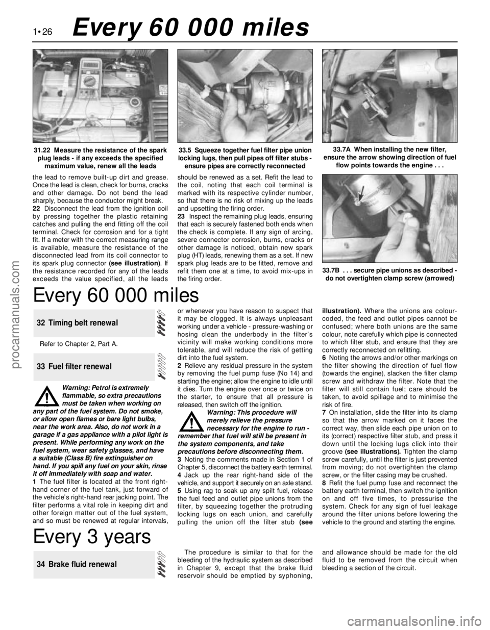
5Using rag to soak up any spilt fuel, release
the fuel feed and outlet pipe unions from the
filter, by squeezing together the protruding
locking lugs on each union, and carefully
pulling the union off the filter stub (seeillustration). Where the unions are colour-
coded, the feed and outlet pipes cannot be
confused; where both unions are the same
colour, note carefully which pipe is connected
to which filter stub, and ensure that they are
correctly reconnected on refitting.
6Noting the arrows and/or other markings on
the filter showing the direction of fuel flow
(towards the engine), slacken the filter clamp
screw and withdraw the filter. Note that the
filter will still contain fuel; care should be
taken, to avoid spillage and to minimise the
risk of fire.
7On installation, slide the filter into its clamp
so that the arrow marked on it faces the
correct way, then slide each pipe union on to
its (correct) respective filter stub, and press it
down until the locking lugs click into their
groove (see illustrations). Tighten the clamp
screw carefully, until the filter is just prevented
from moving; do not overtighten the clamp
screw, or the filter casing may be crushed.
8Refit the fuel pump fuse and reconnect the
battery earth terminal, then switch the ignition
on and off five times, to pressurise the
system. Check for any sign of fuel leakage
around the filter unions before lowering the
vehicle to the ground and starting the engine.
33 Fuel filter renewal
32 Timing belt renewal
33.5 Squeeze together fuel filter pipe union
locking lugs, then pull pipes off filter stubs -
ensure pipes are correctly reconnected33.7A When installing the new filter,
ensure the arrow showing direction of fuel
flow points towards the engine . . .
Every 3 years
The procedure is similar to that for the
bleeding of the hydraulic system as described
in Chapter 9, except that the brake fluid
reservoir should be emptied by syphoning,and allowance should be made for the old
fluid to be removed from the circuit when
bleeding a section of the circuit.
34 Brake fluid renewal
31.22 Measure the resistance of the spark
plug leads - if any exceeds the specified
maximum value, renew all the leads
the lead to remove built-up dirt and grease.
Once the lead is clean, check for burns, cracks
and other damage. Do not bend the lead
sharply, because the conductor might break.
22Disconnect the lead from the ignition coil
by pressing together the plastic retaining
catches and pulling the end fitting off the coil
terminal. Check for corrosion and for a tight
fit. If a meter with the correct measuring range
is available, measure the resistance of the
disconnected lead from its coil connector to
its spark plug connector (see illustration). If
the resistance recorded for any of the leads
exceeds the value specified, all the leadsshould be renewed as a set. Refit the lead to
the coil, noting that each coil terminal is
marked with its respective cylinder number,
so that there is no risk of mixing up the leads
and upsetting the firing order.
23Inspect the remaining plug leads, ensuring
that each is securely fastened both ends when
the check is complete. If any sign of arcing,
severe connector corrosion, burns, cracks or
other damage is noticed, obtain new spark
plug (HT) leads, renewing them as a set. If new
spark plug leads are to be fitted, remove and
refit them one at a time, to avoid mix-ups in
the firing order.
33.7B . . . secure pipe unions as described -
do not overtighten clamp screw (arrowed)
procarmanuals.com
Page 47 of 279
throttle linkage as described in Chapter 4.
Where fitted, disconnect also the cruise
control actuator cable (see Chapter 12).
3Remove the timing belt upper cover (see
Section 9).
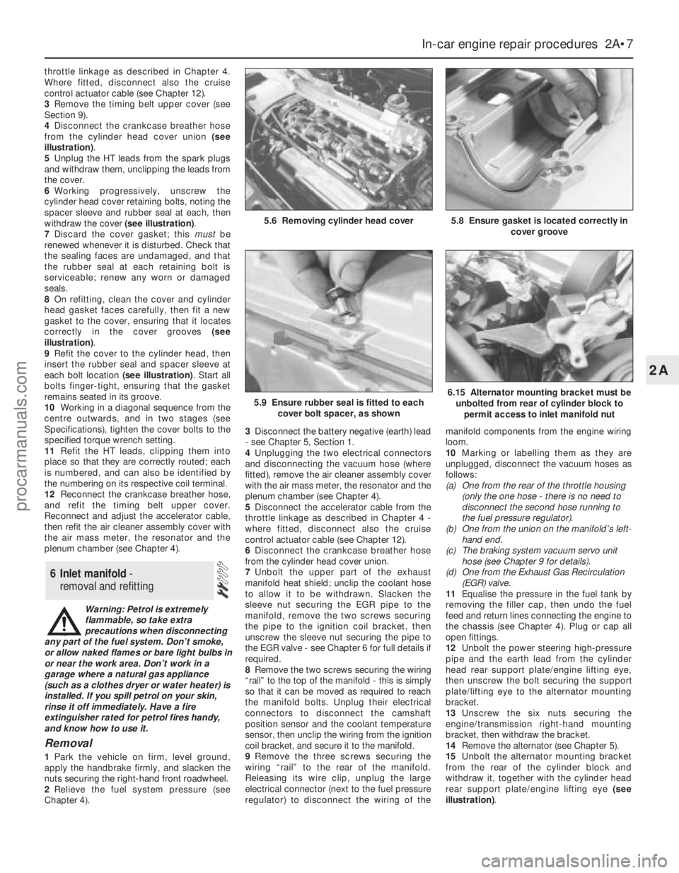
4Disconnect the crankcase breather hose
from the cylinder head cover union (see
illustration).
5Unplug the HT leads from the spark plugs
and withdraw them, unclipping the leads from
the cover.
6Working progressively, unscrew the
cylinder head cover retaining bolts, noting the
spacer sleeve and rubber seal at each, then
withdraw the cover (see illustration).
7Discard the cover gasket; this mustbe
renewed whenever it is disturbed. Check that
the sealing faces are undamaged, and that
the rubber seal at each retaining bolt is
serviceable; renew any worn or damaged
seals.
8On refitting, clean the cover and cylinder
head gasket faces carefully, then fit a new
gasket to the cover, ensuring that it locates
correctly in the cover grooves (see
illustration).
9Refit the cover to the cylinder head, then
insert the rubber seal and spacer sleeve at
each bolt location (see illustration). Start all
bolts finger-tight, ensuring that the gasket
remains seated in its groove.
10Working in a diagonal sequence from the
centre outwards, and in two stages (see
Specifications), tighten the cover bolts to the
specified torque wrench setting.
11Refit the HT leads, clipping them into
place so that they are correctly routed; each
is numbered, and can also be identified by
the numbering on its respective coil terminal.
12Reconnect the crankcase breather hose,
and refit the timing belt upper cover.
Reconnect and adjust the accelerator cable,
then refit the air cleaner assembly cover with
the air mass meter, the resonator and the
plenum chamber (see Chapter 4).
Warning: Petrol is extremely
flammable, so take extra
precautions when disconnecting
any part of the fuel system. Don’t smoke,
or allow naked flames or bare light bulbs in
or near the work area. Don’t work in a
garage where a natural gas appliance
(such as a clothes dryer or water heater) is
installed. If you spill petrol on your skin,
rinse it off immediately. Have a fire
extinguisher rated for petrol fires handy,
and know how to use it.
Removal
1Park the vehicle on firm, level ground,
apply the handbrake firmly, and slacken the
nuts securing the right-hand front roadwheel.
2Relieve the fuel system pressure (see
Chapter 4).3Disconnect the battery negative (earth) lead
- see Chapter 5, Section 1.
4Unplugging the two electrical connectors
and disconnecting the vacuum hose (where
fitted), remove the air cleaner assembly cover
with the air mass meter, the resonator and the
plenum chamber (see Chapter 4).
5Disconnect the accelerator cable from the
throttle linkage as described in Chapter 4 -
where fitted, disconnect also the cruise
control actuator cable (see Chapter 12).
6Disconnect the crankcase breather hose
from the cylinder head cover union.
7Unbolt the upper part of the exhaust
manifold heat shield; unclip the coolant hose
to allow it to be withdrawn. Slacken the
sleeve nut securing the EGR pipe to the
manifold, remove the two screws securing
the pipe to the ignition coil bracket, then
unscrew the sleeve nut securing the pipe to
the EGR valve - see Chapter 6 for full details if
required.
8Remove the two screws securing the wiring
“rail” to the top of the manifold - this is simply
so that it can be moved as required to reach
the manifold bolts. Unplug their electrical
connectors to disconnect the camshaft
position sensor and the coolant temperature
sensor, then unclip the wiring from the ignition
coil bracket, and secure it to the manifold.
9Remove the three screws securing the
wiring “rail” to the rear of the manifold.
Releasing its wire clip, unplug the large
electrical connector (next to the fuel pressure
regulator) to disconnect the wiring of themanifold components from the engine wiring
loom.
10Marking or labelling them as they are
unplugged, disconnect the vacuum hoses as
follows:
(a) One from the rear of the throttle housing
(only the one hose - there is no need to
disconnect the second hose running to
the fuel pressure regulator).
(b) One from the union on the manifold’s left-
hand end.
(c) The braking system vacuum servo unit
hose (see Chapter 9 for details).
(d) One from the Exhaust Gas Recirculation
(EGR) valve.
11Equalise the pressure in the fuel tank by
removing the filler cap, then undo the fuel
feed and return lines connecting the engine to
the chassis (see Chapter 4). Plug or cap all
open fittings.
12Unbolt the power steering high-pressure
pipe and the earth lead from the cylinder
head rear support plate/engine lifting eye,
then unscrew the bolt securing the support
plate/lifting eye to the alternator mounting
bracket.
13Unscrew the six nuts securing the
engine/transmission right-hand mounting
bracket, then withdraw the bracket.
14Remove the alternator (see Chapter 5).
15Unbolt the alternator mounting bracket
from the rear of the cylinder block and
withdraw it, together with the cylinder head
rear support plate/engine lifting eye (see
illustration).
6 Inlet manifold -
removal and refitting
In-car engine repair procedures 2A•7
2A
5.8 Ensure gasket is located correctly in
cover groove5.6 Removing cylinder head cover
5.9 Ensure rubber seal is fitted to each
cover bolt spacer, as shown6.15 Alternator mounting bracket must be
unbolted from rear of cylinder block to
permit access to inlet manifold nut
procarmanuals.com
Page 70 of 279
safely and with relative ease, and which may
have to be hired or borrowed, includes (in
addition to the engine hoist) a heavy-duty trolley
jack, a strong pair of axle stands, some wooden
blocks, and an engine dolly (a low, wheeled
platform capable of taking the weight of the
engine/transmission, so that it can be moved
easily when on the ground). A complete set of
spanners and sockets (as described in the front
of this manual) will obviously be needed,
together with plenty of rags and cleaning
solvent for mopping-up spilled oil, coolant and
fuel. If the hoist is to be hired, make sure that
you arrange for it in advance, and perform all of
the operations possible without it beforehand.
This will save you money and time.
Plan for the vehicle to be out of use for
quite a while. A machine shop will be required
to perform some of the work which the do-it-
yourselfer can’t accomplish without special
equipment. These establishments often have
a busy schedule, so it would be a good idea
to consult them before removing the engine,
to accurately estimate the amount of time
required to rebuild or repair components that
may need work.
Always be extremely careful when removing
and installing the engine/transmission.
Serious injury can result from careless
actions. By planning ahead and taking your
time, the job (although a major task) can be
accomplished successfully.
Warning: Petrol is extremely
flammable, so take extra
precautions when disconnecting
any part of the fuel system. Don’t
smoke, or allow naked flames or bare light
bulbs in or near the work area, and don’t
work in a garage where a natural gas
appliance (such as a clothes dryer or water
heater) is installed. If you spill petrol on
your skin, rinse it off immediately. Have a
fire extinguisher rated for petrol fires
handy, and know how to use it.Note: Read through the entire Section, as well
as reading the advice in the preceding Section,
before beginning this procedure. The engine
and transmission are removed as a unit,
lowered to the ground and removed from
underneath, then separated outside the vehicle.
Removal
1Park the vehicle on firm, level ground, apply
the handbrake firmly, and slacken the nuts
securing both front roadwheels.
2Relieve the fuel system pressure (see
Chapter 4).
3Disconnect the battery negative (earth) lead
- see Chapter 5, Section 1. For better access
the battery may be removed completely (see
Chapter 5).
4Place protective covers on the wings and
engine compartment front crossmember, then
remove the bonnet (see Chapter 11).
5Whenever you disconnect any vacuum
lines, coolant and emissions hoses, wiring
loom connectors, earth straps and fuel lines
as part of the following procedure, always
label them clearly, so that they can be
correctly reassembled.
6Unplug the two electrical connectors,disconnect the vacuum hose (where fitted)
and disconnect the crankcase breather hose
from the cylinder head cover, then remove the
complete air cleaner assembly, with the air
mass meter, the resonator and the plenum
chamber (see Chapter 4).
7Equalise the pressure in the fuel tank by
removing the filler cap, then undo the fuel
feed and return lines connecting the engine to
the chassis (see Chapter 4). Plug or cap all
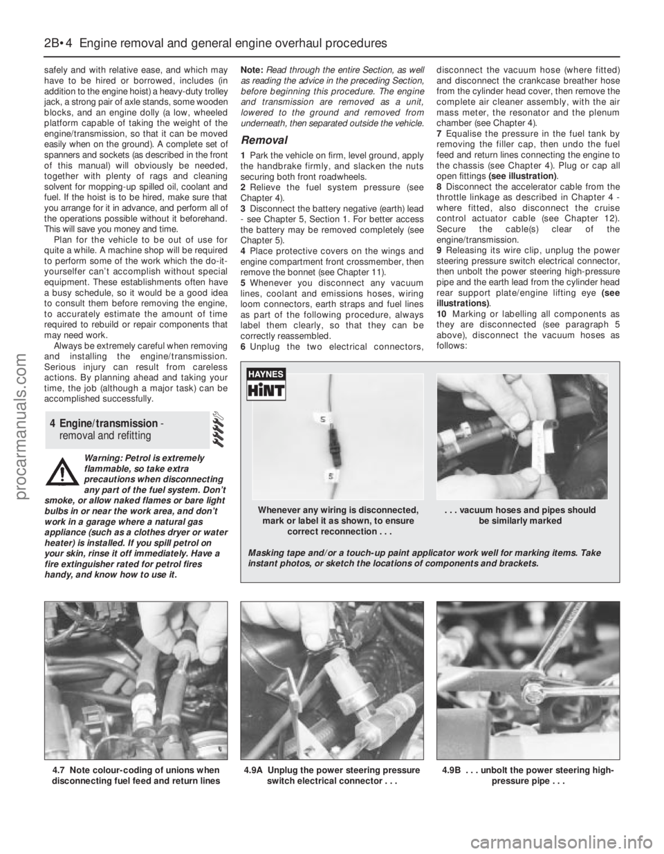
open fittings (see illustration).
8Disconnect the accelerator cable from the
throttle linkage as described in Chapter 4 -
where fitted, also disconnect the cruise
control actuator cable (see Chapter 12).
Secure the cable(s) clear of the
engine/transmission.
9Releasing its wire clip, unplug the power
steering pressure switch electrical connector,
then unbolt the power steering high-pressure
pipe and the earth lead from the cylinder head
rear support plate/engine lifting eye (see
illustrations).
10Marking or labelling all components as
they are disconnected (see paragraph 5
above), disconnect the vacuum hoses as
follows:
4 Engine/transmission -
removal and refitting
2B•4 Engine removal and general engine overhaul procedures
4.7 Note colour-coding of unions when
disconnecting fuel feed and return lines4.9A Unplug the power steering pressure
switch electrical connector . . .4.9B . . . unbolt the power steering high-
pressure pipe . . .
Whenever any wiring is disconnected, . . . vacuum hoses and pipes should
mark or label it as shown, to ensure be similarly marked
correct reconnection . . .
Masking tape and/or a touch-up paint applicator work well for marking items. Take
instant photos, or sketch the locations of components and brackets.
procarmanuals.com
Page 93 of 279
sender’s electrical connector, and use a
jumper wire to connect the white/red wire to a
clean earth point (bare metal) on the engine.
Switch on the ignition without starting the
engine. If the gauge now indicates Hot, renew
the sender.
5If the gauge still does not work, the circuit
may be open, or the gauge may be faulty. See
Chapter 12 for additional information.
Removal
6Unbolt the resonator support bracket from
the engine compartment front crossmember.
Slacken the two clamp screws securing the
resonator to the air mass meter and plenum
chamber hoses, then swing the resonator up
clear of the thermostat housing (see Chap-
ter 4).
7Drain the cooling system (see Chapter 1).
8Disconnect the expansion tank coolant
hose and the radiator top hose from the
thermostat housing’s water outlet, then
disconnect the metal coolant pipe/hose from
the thermostat.
9Unplug the electrical connector from the
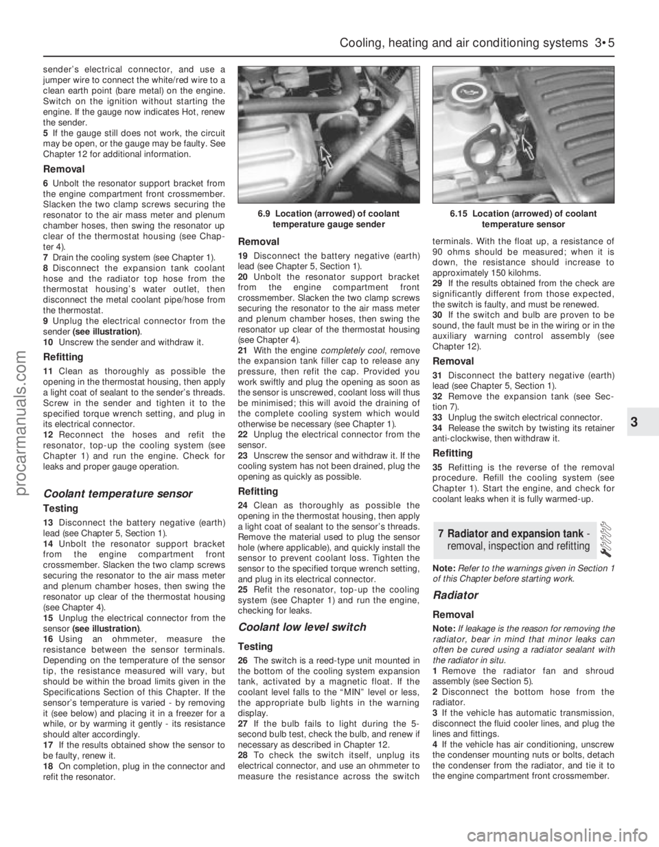
sender (see illustration).
10Unscrew the sender and withdraw it.
Refitting
11Clean as thoroughly as possible the
opening in the thermostat housing, then apply
a light coat of sealant to the sender’s threads.
Screw in the sender and tighten it to the
specified torque wrench setting, and plug in
its electrical connector.
12Reconnect the hoses and refit the
resonator, top-up the cooling system (see
Chapter 1) and run the engine. Check for
leaks and proper gauge operation.
Coolant temperature sensor
Testing
13Disconnect the battery negative (earth)
lead (see Chapter 5, Section 1).
14Unbolt the resonator support bracket
from the engine compartment front
crossmember. Slacken the two clamp screws
securing the resonator to the air mass meter
and plenum chamber hoses, then swing the
resonator up clear of the thermostat housing
(see Chapter 4).
15Unplug the electrical connector from the
sensor (see illustration).
16Using an ohmmeter, measure the
resistance between the sensor terminals.
Depending on the temperature of the sensor
tip, the resistance measured will vary, but
should be within the broad limits given in the
Specifications Section of this Chapter. If the
sensor’s temperature is varied - by removing
it (see below) and placing it in a freezer for a
while, or by warming it gently - its resistance
should alter accordingly.
17If the results obtained show the sensor to
be faulty, renew it.
18On completion, plug in the connector and
refit the resonator.
Removal
19Disconnect the battery negative (earth)
lead (see Chapter 5, Section 1).
20Unbolt the resonator support bracket
from the engine compartment front
crossmember. Slacken the two clamp screws
securing the resonator to the air mass meter
and plenum chamber hoses, then swing the
resonator up clear of the thermostat housing
(see Chapter 4).
21With the engine completely cool, remove
the expansion tank filler cap to release any
pressure, then refit the cap. Provided you
work swiftly and plug the opening as soon as
the sensor is unscrewed, coolant loss will thus
be minimised; this will avoid the draining of
the complete cooling system which would
otherwise be necessary (see Chapter 1).
22Unplug the electrical connector from the
sensor.
23Unscrew the sensor and withdraw it. If the
cooling system has not been drained, plug the
opening as quickly as possible.
Refitting
24Clean as thoroughly as possible the
opening in the thermostat housing, then apply
a light coat of sealant to the sensor’s threads.
Remove the material used to plug the sensor
hole (where applicable), and quickly install the
sensor to prevent coolant loss. Tighten the
sensor to the specified torque wrench setting,
and plug in its electrical connector.
25Refit the resonator, top-up the cooling
system (see Chapter 1) and run the engine,
checking for leaks.
Coolant low level switch
Testing
26The switch is a reed-type unit mounted in
the bottom of the cooling system expansion
tank, activated by a magnetic float. If the
coolant level falls to the “MIN” level or less,
the appropriate bulb lights in the warning
display.
27If the bulb fails to light during the 5-
second bulb test, check the bulb, and renew if
necessary as described in Chapter 12.
28To check the switch itself, unplug its
electrical connector, and use an ohmmeter to
measure the resistance across the switchterminals. With the float up, a resistance of
90 ohms should be measured; when it is
down, the resistance should increase to
approximately 150 kilohms.
29If the results obtained from the check are
significantly different from those expected,
the switch is faulty, and must be renewed.
30If the switch and bulb are proven to be
sound, the fault must be in the wiring or in the
auxiliary warning control assembly (see
Chapter 12).
Removal
31Disconnect the battery negative (earth)
lead (see Chapter 5, Section 1).
32Remove the expansion tank (see Sec-
tion 7).
33Unplug the switch electrical connector.
34Release the switch by twisting its retainer
anti-clockwise, then withdraw it.
Refitting
35Refitting is the reverse of the removal
procedure. Refill the cooling system (see
Chapter 1). Start the engine, and check for
coolant leaks when it is fully warmed-up.
Note:Refer to the warnings given in Section 1
of this Chapter before starting work.
Radiator
Removal
Note:If leakage is the reason for removing the
radiator, bear in mind that minor leaks can
often be cured using a radiator sealant with
the radiator in situ.
1Remove the radiator fan and shroud
assembly (see Section 5).
2Disconnect the bottom hose from the
radiator.
3If the vehicle has automatic transmission,
disconnect the fluid cooler lines, and plug the
lines and fittings.
4If the vehicle has air conditioning, unscrew
the condenser mounting nuts or bolts, detach
the condenser from the radiator, and tie it to
the engine compartment front crossmember.
7 Radiator and expansion tank -
removal, inspection and refitting
Cooling, heating and air conditioning systems 3•5
3
6.9 Location (arrowed) of coolant
temperature gauge sender6.15 Location (arrowed) of coolant
temperature sensor
procarmanuals.com
Page 100 of 279
This Chapter is concerned with those
features of the engine management system
that supply clean fuel and air to the engine,
meter it in the required proportions, and
dispose of the results. Since the emission
control sub-systems modify the functions of
both the fuel and exhaust sub-systems, all of
which are integral parts of the whole engine
management system, there are many cross-
references to Chapters 5 and 6. Information
on the electronic control system, its fault
diagnosis, sensors and actuators, is given in
Chapter 6.
The air intake system consists of several
plastics components designed to eliminate
induction roar as much as possible. The air
intake tube (opening behind the direction
indicator/headlight assembly) is connected,
via small and large resonators located under
the front left-hand wing, to the air cleaner
assembly in the engine compartment. Once it
has passed through the filter element and the
air mass meter, the air enters the plenum
chamber mounted above the throttle housing
and inlet manifold; the resonator mounted in
the engine compartment further reduces noise
levels.
The fuel system consists of a plastic tank
(mounted under the body, beneath the rear
seats), combined metal and plastic fuel hoses,
an electric fuel pump mounted in the fuel tank,
and an electronic fuel injection system.
The exhaust system consists of an exhaust
manifold, the front downpipe and catalytic
converter and, on production-fit systems, a
rear section incorporating two or three
silencers and the tailpipe assembly. The
service replacement exhaust system consists
of three or four sections: the front
downpipe/catalytic converter, the
intermediate pipe and front silencer, and the
tailpipe and rear silencer. On some versions,
the tailpipe is in two pieces, with two rear
silencers. The system is suspended
throughout its entire length by rubber
mountings.
Extreme caution should be exercised when
dealing with either the fuel or exhaust
systems. Fuel is a primary element for
combustion. Be very careful! The exhaust
system is an area for exercising caution, as it
operates at very high temperatures. Serious
burns can result from even momentary
contact with any part of the exhaust system,
and the fire risk is ever-present. The catalytic
converter in particular runs at very high
temperatures - refer to the information in
Chapter 6.
Warning: Many of the procedures
in this Chapter require the
removal of fuel lines and
connections, which may result in
some fuel spillage. Petrol is extremely
flammable, so take extra precautionswhen you work on any part of the fuel
system. Don’t smoke, or allow open flames
or bare light bulbs, near the work area.
Don’t work in a garage where a natural
gas-type appliance (such as a water
heater or clothes dryer) with a pilot light is
present. If you spill any fuel on your skin,
rinse it off immediately with soap and
water. When you perform any kind of work
on the fuel system, wear safety glasses,
and have a Class B type fire extinguisher
on hand. Before carrying out any operation
on the fuel system, refer also to the
precautions given in “Safety first!” at the
beginning of this manual, and follow them
implicitly. Petrol is a highly-dangerous and
volatile liquid, and the precautions
necessary when handling it cannot be
overstressed.
Warning: The fuel system will
remain pressurised for long
periods of time after the engine is
switched off - this pressure must
be released before any part of the system
is disturbed. Petrol is extremely
flammable, so take extra precautions
when you work on any part of the fuel
system. Don’t smoke, or allow open flames
or bare light bulbs, near the work area.
Don’t work in a garage where a natural
gas-type appliance (such as a water
heater or clothes dryer) with a pilot light is
present. If you spill any fuel on your skin,
rinse it off immediately with soap and
water. When you perform any kind of work
on the fuel system, wear safety glasses,
and have a Class B type fire extinguisher
on hand.
1The fuel system referred to in this Chapter
is defined as the fuel tank and tank-mounted
fuel pump/fuel gauge sender unit, the fuel
filter, the fuel injectors and the pressure
regulator in the injector rail, and the metal
pipes and flexible hoses of the fuel lines
between these components. All these contain
fuel, which will be under pressure while the
engine is running and/or while the ignition is
switched on.
2The pressure will remain for some time after
the ignition has been switched off, and must
be relieved before any of these components is
disturbed for servicing work.
3The simplest method is simply to
disconnect the fuel pump’s electrical supply
while the engine is running - either by
removing the fuel pump fuse (number 14), or
by lifting the red button on the fuel cut-off
switch (see Section 13) - and to allow the
engine to idle until it dies through lack of fuel
pressure. Turn the engine over once or twice
on the starter to ensure that all pressure is
released, then switch off the ignition; do not
forget to refit the fuse (or depress the redbutton, as appropriate) when work is
complete.
4The Ford method of depressurisation is to
use service tool 29-033 fitted to the fuel rail
pressure test/release fitting - a Schrader-type
valve with a blue plastic cap, located on the
union of the fuel feed line and the fuel rail - to
release the pressure, using a suitable
container and wads of rag to catch the spilt
fuel. Do notsimply depress the valve core to
release fuel pressure - droplets of fuel will
spray out, with a consequent risk of fire, and
of personal injury through fuel getting into
your eyes.
Warning: Either procedure will
merely relieve the increased
pressure necessary for the
engine to run. Remember that
fuel will still be present in the system
components, and take precautions
accordingly before disconnecting any of
them.
5Note that, once the fuel system has been
depressurised and drained (even partially), it
will take significantly longer to restart the
engine - perhaps several seconds of cranking
- before the system is refilled and pressure
restored.
Warning: The fuel system
pressure must be released before
any part of the system is
disturbed - see Section 2. Petrol
is extremely flammable, so take extra
precautions when you work on any part of
the fuel system. Don’t smoke, or allow
open flames or bare light bulbs, near the
work area. Don’t work in a garage where a
natural gas-type appliance (such as a
water heater or clothes dryer) with a pilot
light is present. If you spill any fuel on your
skin, rinse it off immediately with soap and
water. When you perform any kind of work
on the fuel system, wear safety glasses,
and have a Class B type fire extinguisher
on hand.
Disconnecting and connecting
quick-release couplings
1Quick-release couplings are employed at all
unions in the fuel feed and return lines.
2Before disconnecting any fuel system
component, relieve the residual pressure in
the system (see Section 2), and equalise tank
pressure by removing the fuel filler cap.
Warning: This procedure will
merely relieve the increased
pressure necessary for the
engine to run - remember that
fuel will still be present in the system
components, and take precautions
accordingly before disconnecting any of
them.
3 Fuel lines and fittings-
general information
2 Fuel system - depressurisation
1 General information and
precautions
4•2 Fuel and exhaust systems
procarmanuals.com
Page 103 of 279
which pulley, disconnect the first cable end
nipple from the throttle actuator’s upper
pulley, then slide the cable outer upwards out
of the actuator housing. Disconnect the
second cable in the same way from the
actuator’s lower pulley.
6Working in the passenger compartment,
reach up to the top of the accelerator pedal.
Pull the end fitting and collar out of the pedal,
then release the cable inner wire through the
slot in the pedal. Tie a length of string to the
end of the cable.
7Returning to the engine compartment, pull
the cable through the bulkhead until the string
can be untied and the pedal-to-actuator cable
removed.
Refitting
8Refitting is the reverse of the removal
procedure. Use the string to draw the pedal-
to-actuator cable through the bulkhead.
Ensure that each cable end is connected to
the correct actuator pulley.
9Adjust both cables as described below.
Adjustment
Note:Both sections of the cable must be
adjusted together, even if only one has been
disturbed.
10Remove the plenum chamber (see
Section 4).
11Remove the metal clip from the adjuster
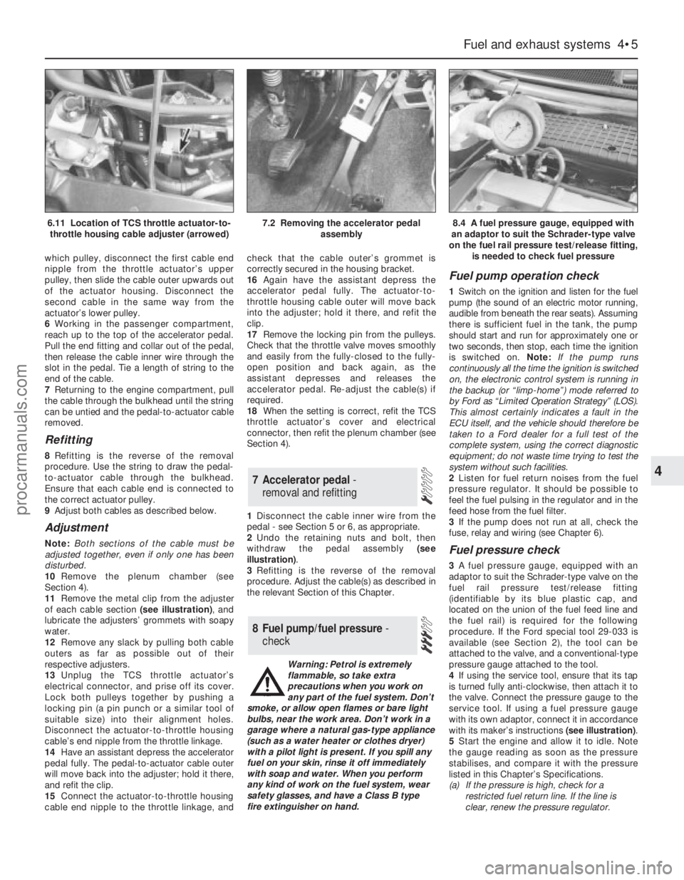
of each cable section (see illustration), and
lubricate the adjusters’ grommets with soapy
water.
12Remove any slack by pulling both cable
outers as far as possible out of their
respective adjusters.
13Unplug the TCS throttle actuator’s
electrical connector, and prise off its cover.
Lock both pulleys together by pushing a
locking pin (a pin punch or a similar tool of
suitable size) into their alignment holes.
Disconnect the actuator-to-throttle housing
cable’s end nipple from the throttle linkage.
14Have an assistant depress the accelerator
pedal fully. The pedal-to-actuator cable outer
will move back into the adjuster; hold it there,
and refit the clip.
15Connect the actuator-to-throttle housing
cable end nipple to the throttle linkage, andcheck that the cable outer’s grommet is
correctly secured in the housing bracket.
16Again have the assistant depress the
accelerator pedal fully. The actuator-to-
throttle housing cable outer will move back
into the adjuster; hold it there, and refit the
clip.
17Remove the locking pin from the pulleys.
Check that the throttle valve moves smoothly
and easily from the fully-closed to the fully-
open position and back again, as the
assistant depresses and releases the
accelerator pedal. Re-adjust the cable(s) if
required.
18When the setting is correct, refit the TCS
throttle actuator’s cover and electrical
connector, then refit the plenum chamber (see
Section 4).
1Disconnect the cable inner wire from the
pedal - see Section 5 or 6, as appropriate.
2Undo the retaining nuts and bolt, then
withdraw the pedal assembly (see
illustration).
3Refitting is the reverse of the removal
procedure. Adjust the cable(s) as described in
the relevant Section of this Chapter.
Warning: Petrol is extremely
flammable, so take extra
precautions when you work on
any part of the fuel system. Don’t
smoke, or allow open flames or bare light
bulbs, near the work area. Don’t work in a
garage where a natural gas-type appliance
(such as a water heater or clothes dryer)
with a pilot light is present. If you spill any
fuel on your skin, rinse it off immediately
with soap and water. When you perform
any kind of work on the fuel system, wear
safety glasses, and have a Class B type
fire extinguisher on hand.
Fuel pump operation check
1Switch on the ignition and listen for the fuel
pump (the sound of an electric motor running,
audible from beneath the rear seats). Assuming
there is sufficient fuel in the tank, the pump
should start and run for approximately one or
two seconds, then stop, each time the ignition
is switched on. Note:If the pump runs
continuously all the time the ignition is switched
on, the electronic control system is running in
the backup (or “limp-home”) mode referred to
by Ford as “Limited Operation Strategy” (LOS).
This almost certainly indicates a fault in the
ECU itself, and the vehicle should therefore be
taken to a Ford dealer for a full test of the
complete system, using the correct diagnostic
equipment; do not waste time trying to test the
system without such facilities.
2Listen for fuel return noises from the fuel
pressure regulator. It should be possible to
feel the fuel pulsing in the regulator and in the
feed hose from the fuel filter.
3If the pump does not run at all, check the
fuse, relay and wiring (see Chapter 6).
Fuel pressure check
3A fuel pressure gauge, equipped with an
adaptor to suit the Schrader-type valve on the
fuel rail pressure test/release fitting
(identifiable by its blue plastic cap, and
located on the union of the fuel feed line and
the fuel rail) is required for the following
procedure. If the Ford special tool 29-033 is
available (see Section 2), the tool can be
attached to the valve, and a conventional-type
pressure gauge attached to the tool.
4If using the service tool, ensure that its tap
is turned fully anti-clockwise, then attach it to
the valve. Connect the pressure gauge to the
service tool. If using a fuel pressure gauge
with its own adaptor, connect it in accordance
with its maker’s instructions (see illustration).
5Start the engine and allow it to idle. Note
the gauge reading as soon as the pressure
stabilises, and compare it with the pressure
listed in this Chapter’s Specifications.
(a) If the pressure is high, check for a
restricted fuel return line. If the line is
clear, renew the pressure regulator.
8 Fuel pump/fuel pressure -
check
7 Accelerator pedal -
removal and refitting
Fuel and exhaust systems 4•5
4
6.11 Location of TCS throttle actuator-to-
throttle housing cable adjuster (arrowed)7.2 Removing the accelerator pedal
assembly8.4 A fuel pressure gauge, equipped with
an adaptor to suit the Schrader-type valve
on the fuel rail pressure test/release fitting,
is needed to check fuel pressure
procarmanuals.com