1993 FORD MONDEO headlights
[x] Cancel search: headlightsPage 8 of 279
Seat belts and seats
Note: The following checks are applicable to
all seat belts, front and rear.
MExamine the webbing of all the belts
(including rear belts if fitted) for cuts, serious
fraying or deterioration. Fasten and unfasten
each belt to check the buckles. If applicable,
check the retracting mechanism. Check the
security of all seat belt mountings accessible
from inside the vehicle.
MThe front seats themselves must be
securely attached and the backrests must
lock in the upright position.
Doors
MBoth front doors must be able to be opened
and closed from outside and inside, and must
latch securely when closed.
Vehicle identification
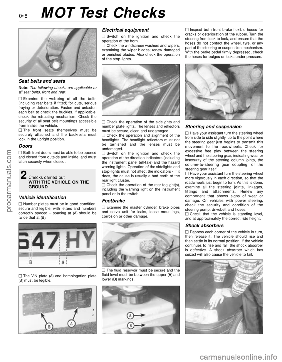
MNumber plates must be in good condition,
secure and legible, with letters and numbers
correctly spaced – spacing at (A) should be
twice that at (B).
MThe VIN plate (A) and homologation plate
(B) must be legible.
Electrical equipment
MSwitch on the ignition and check the
operation of the horn.
MCheck the windscreen washers and wipers,
examining the wiper blades; renew damaged
or perished blades. Also check the operation
of the stop-lights.
MCheck the operation of the sidelights and
number plate lights. The lenses and reflectors
must be secure, clean and undamaged.
MCheck the operation and alignment of the
headlights. The headlight reflectors must not
be tarnished and the lenses must be
undamaged.
MSwitch on the ignition and check the
operation of the direction indicators (including
the instrument panel tell-tale) and the hazard
warning lights. Operation of the sidelights and
stop-lights must not affect the indicators - if it
does, the cause is usually a bad earth at the
rear light cluster.
MCheck the operation of the rear foglight(s),
including the warning light on the instrument
panel or in the switch.
Footbrake
MExamine the master cylinder, brake pipes
and servo unit for leaks, loose mountings,
corrosion or other damage.
MThe fluid reservoir must be secure and the
fluid level must be between the upper (A) and
lower (B) markings.MInspect both front brake flexible hoses for
cracks or deterioration of the rubber. Turn the
steering from lock to lock, and ensure that the
hoses do not contact the wheel, tyre, or any
part of the steering or suspension mechanism.
With the brake pedal firmly depressed, check
the hoses for bulges or leaks under pressure.
Steering and suspension
MHave your assistant turn the steering wheel
from side to side slightly, up to the point where
the steering gear just begins to transmit this
movement to the roadwheels. Check for
excessive free play between the steering
wheel and the steering gear, indicating wear or
insecurity of the steering column joints, the
column-to-steering gear coupling, or the
steering gear itself.
MHave your assistant turn the steering wheel
more vigorously in each direction, so that the
roadwheels just begin to turn. As this is done,
examine all the steering joints, linkages,
fittings and attachments. Renew any
component that shows signs of wear or
damage. On vehicles with power steering,
check the security and condition of the
steering pump, drivebelt and hoses.
MCheck that the vehicle is standing level,
and at approximately the correct ride height.
Shock absorbers
MDepress each corner of the vehicle in turn,
then release it. The vehicle should rise and
then settle in its normal position. If the vehicle
continues to rise and fall, the shock absorber
is defective. A shock absorber which has
seized will also cause the vehicle to fail.
2Checks carried out
WITH THE VEHICLE ON THE
GROUND
0•8MOT Test Checks
procarmanuals.com
Page 109 of 279
rings, and intend to re-use the same injectors,
remove the old nose seal and O-rings, and
discard them.
22Further testing of the injector(s) is beyond
the scope of the home mechanic. If you are in
doubt as to the status of any injector(s), it can
be tested at a dealer service department.
23Refitting is the reverse of the removal
procedure, noting the following points:
(a) Lubricate each nose seal and O-ring with
clean engine oil on installation.
(b) Locate each injector carefully in the fuel
rail recess, ensuring that the locating tab
on the injector head fits into the slot
provided in the rail. Tighten the bolts to
the specified torque.
(c) Fit a new seal to each fuel rail nose, and
ensure the seals are not displaced as the
rail is refitted. Ensure that the fuel rail is
settled fully in the manifold before
tightening the three bolts evenly and to
the torque wrench setting specified.
(d) Fasten the fuel feed and return quick-
release couplings as described in Sec-
tion 3.
(e) Ensure that the breather hose, vacuum
hose and wiring are routed correctly, and
secured on reconnection by any clips or
ties provided.
(f) On completion, switch the ignition on and
off five times, to activate the fuel pump and
pressurise the system, without cranking
the engine. Check for signs of fuel leaks
around all disturbed unions and joints
before attempting to start the engine.
Fuel pressure regulator
Check
24Refer to the fuel pump/fuel pressure
check procedure (see Section 8).
Renewal
25Relieve the residual pressure in the fuel
system (see Section 2), and equalise tank
pressure by removing the fuel filler cap.
Warning: This procedure will
merely relieve the increased
pressure necessary for the engine
to run - remember that fuel will
still be present in the system components,
and take precautions accordingly before
disconnecting any of them.26Disconnect the battery negative (earth)
lead - see Chapter 5, Section 1.
27Remove the plenum chamber (see
Section 4).
28Disconnect the vacuum hose from the
regulator.
29Unscrew the two regulator retaining bolts,
place a wad of clean rag to soak up any spilt
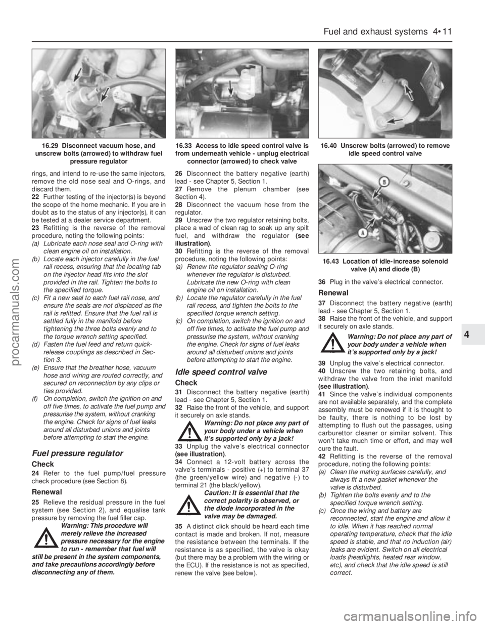
fuel, and withdraw the regulator (see
illustration).
30Refitting is the reverse of the removal
procedure, noting the following points:
(a) Renew the regulator sealing O-ring
whenever the regulator is disturbed.
Lubricate the new O-ring with clean
engine oil on installation.
(b) Locate the regulator carefully in the fuel
rail recess, and tighten the bolts to the
specified torque wrench setting.
(c) On completion, switch the ignition on and
off five times, to activate the fuel pump and
pressurise the system, without cranking
the engine. Check for signs of fuel leaks
around all disturbed unions and joints
before attempting to start the engine.
Idle speed control valve
Check
31Disconnect the battery negative (earth)
lead - see Chapter 5, Section 1.
32Raise the front of the vehicle, and support
it securely on axle stands.
Warning: Do not place any part of
your body under a vehicle when
it’s supported only by a jack!
33Unplug the valve’s electrical connector
(see illustration).
34Connect a 12-volt battery across the
valve’s terminals - positive (+) to terminal 37
(the green/yellow wire) and negative (-) to
terminal 21 (the black/yellow).
Caution: It is essential that the
correct polarity is observed, or
the diode incorporated in the
valve may be damaged.
35A distinct click should be heard each time
contact is made and broken. If not, measure
the resistance between the terminals. If the
resistance is as specified, the valve is okay
(but there may be a problem with the wiring or
the ECU). If the resistance is not as specified,
renew the valve (see below).36Plug in the valve’s electrical connector.
Renewal
37Disconnect the battery negative (earth)
lead - see Chapter 5, Section 1.
38Raise the front of the vehicle, and support
it securely on axle stands.
Warning: Do not place any part of
your body under a vehicle when
it’s supported only by a jack!
39Unplug the valve’s electrical connector.
40Unscrew the two retaining bolts, and
withdraw the valve from the inlet manifold
(see illustration).
41Since the valve’s individual components
are not available separately, and the complete
assembly must be renewed if it is thought to
be faulty, there is nothing to be lost by
attempting to flush out the passages, using
carburettor cleaner or similar solvent. This
won’t take much time or effort, and may well
cure the fault.
42Refitting is the reverse of the removal
procedure, noting the following points:
(a) Clean the mating surfaces carefully, and
always fit a new gasket whenever the
valve is disturbed.
(b) Tighten the bolts evenly and to the
specified torque wrench setting.
(c) Once the wiring and battery are
reconnected, start the engine and allow it
to idle. When it has reached normal
operating temperature, check that the idle
speed is stable, and that no induction (air)
leaks are evident. Switch on all electrical
loads (headlights, heated rear window,
etc), and check that the idle speed is still
correct.
Fuel and exhaust systems 4•11
4
16.43 Location of idle-increase solenoid
valve (A) and diode (B)
16.29 Disconnect vacuum hose, and
unscrew bolts (arrowed) to withdraw fuel
pressure regulator16.33 Access to idle speed control valve is
from underneath vehicle - unplug electrical
connector (arrowed) to check valve16.40 Unscrew bolts (arrowed) to remove
idle speed control valve
procarmanuals.com
Page 115 of 279
5Undo the sensor’s retaining screw and
withdraw the sensor. The sensor’s bracket
cannot be unbolted from the cylinder
block/crankcase unless the transmission and
flywheel/driveplate have been removed (see
Chapter 2).
6Refitting is the reverse of the removal
procedure.
General information
The charging system includes the
alternator, an internal voltage regulator, a no-
charge (or “ignition”) warning light, the
battery, and the wiring between all the
components. The charging system supplies
electrical power for the ignition system, the
lights, the radio, etc. The alternator is driven
by the auxiliary drivebelt at the front (right-
hand end) of the engine.
The purpose of the voltage regulator is to
limit the alternator’s voltage to a preset value.
This prevents power surges, circuit overloads,
etc., during peak voltage output.
The charging system doesn’t ordinarily
require periodic maintenance. However, the
drivebelt, battery and wires and connections
should be inspected at the intervals outlined
in Chapter 1.
The dashboard warning light should come
on when the ignition key is turned to positions
“II” or “III”, then should go off immediately the
engine starts. If it remains on, or if it comes on
while the engine is running, there is a
malfunction in the charging system (see
Section 11). If the light does not come on
when the ignition key is turned, and the bulb is
sound (see Chapter 12), there is a fault in the
alternator.
Precautions
Be very careful when making electrical
circuit connections to a vehicle equipped with
an alternator, and note the following:
(a) When reconnecting wires to the alternator
from the battery, be sure to note the
polarity.
(b) Before using arc-welding equipment to
repair any part of the vehicle, disconnect
the wires from the alternator and the
battery terminals.
(c) Never start the engine with a battery
charger connected.
(d) Always disconnect both battery leads
before using a battery charger.
(e) The alternator is driven by an engine
drivebelt which could cause serious injury
if your hand, hair or clothes become
entangled in it with the engine running.
(f) Because the alternator is connected
directly to the battery, it could arc or
cause a fire if overloaded or shorted-out.
(g) Wrap a plastic bag over the alternator,
and secure it with rubber bands, beforesteam-cleaning or pressure-washing the
engine.
(h) Never disconnect the alternator terminals
while the engine is running.
1If a malfunction occurs in the charging
circuit, don’t automatically assume that the
alternator is causing the problem. First check
the following items:
(a) Check the tension and condition of the
auxiliary drivebelt - renew it if it is worn or
deteriorated (see Chapter 1).
(b) Ensure the alternator mounting bolts and
nuts are tight.
(c) Inspect the alternator wiring harness and
the electrical connections at the
alternator; they must be in good
condition, and tight.
(d) Check the large main fuses in the engine
compartment (see Chapter 12). If any is
blown, determine the cause, repair the
circuit and renew the fuse (the vehicle
won’t start and/or the accessories won’t
work if the fuse is blown).
(e) Start the engine and check the alternator
for abnormal noises - for example, a
shrieking or squealing sound may indicate
a badly-worn bearing or brush.
(f) Make sure that the battery is fully-charged
- one bad cell in a battery can cause
overcharging by the alternator.
(g) Disconnect the battery leads (negative
first, then positive). Inspect the battery
posts and the lead clamps for corrosion.
Clean them thoroughly if necessary (see
Section 3 and Chapter 1). Reconnect the
lead to the negative terminal.
(h) With the ignition and all accessories
switched off, insert a test light between
the battery negative post and the
disconnected negative lead clamp:
(1) If the test light does not come on, re-
attach the clamp and proceed to the next
step.
(2) If the test light comes on, there is a short
in the electrical system of the vehicle. The
short must be repaired before the
charging system can be checked.
(3) To find the short, disconnect the
alternator wiring harness:
(a) If the light goes out, the alternator is
at fault.
(b) If the light stays on, remove each fuse
until it goes out - this will tell you
which component is short-circuited.
2Using a voltmeter, check the battery
voltage with the engine off. It should be
approximately 12 volts.
3Start the engine and check the battery
voltage again. Increase engine speed until the
voltmeter reading remains steady; it should
now be approximately 13.5 to 14.6 volts.
4Switch on as many electrical accessories
(eg the headlights, heated rear window andheater blower) as possible, and check that the
alternator maintains the regulated voltage at
around 13 to 14 volts. The voltage may drop
and then come back up; it may also be
necessary to increase engine speed slightly,
even if the charging system is working
properly.
5If the voltage reading is greater than the
specified charging voltage, renew the voltage
regulator (see Section 13).
6If the voltmeter reading is less than that
specified, the fault may be due to worn
brushes, weak brush springs, a faulty voltage
regulator, a faulty diode, a severed phase
winding, or worn or damaged slip rings. The
brushes and slip rings may be checked (see
Section 13), but if the fault persists, the
alternator should be renewed or taken to an
auto-electrician for testing and repair.
1Disconnect the battery negative (earth) lead
- see Section 1.
2Remove the plenum chamber (see Chap-
ter 4).
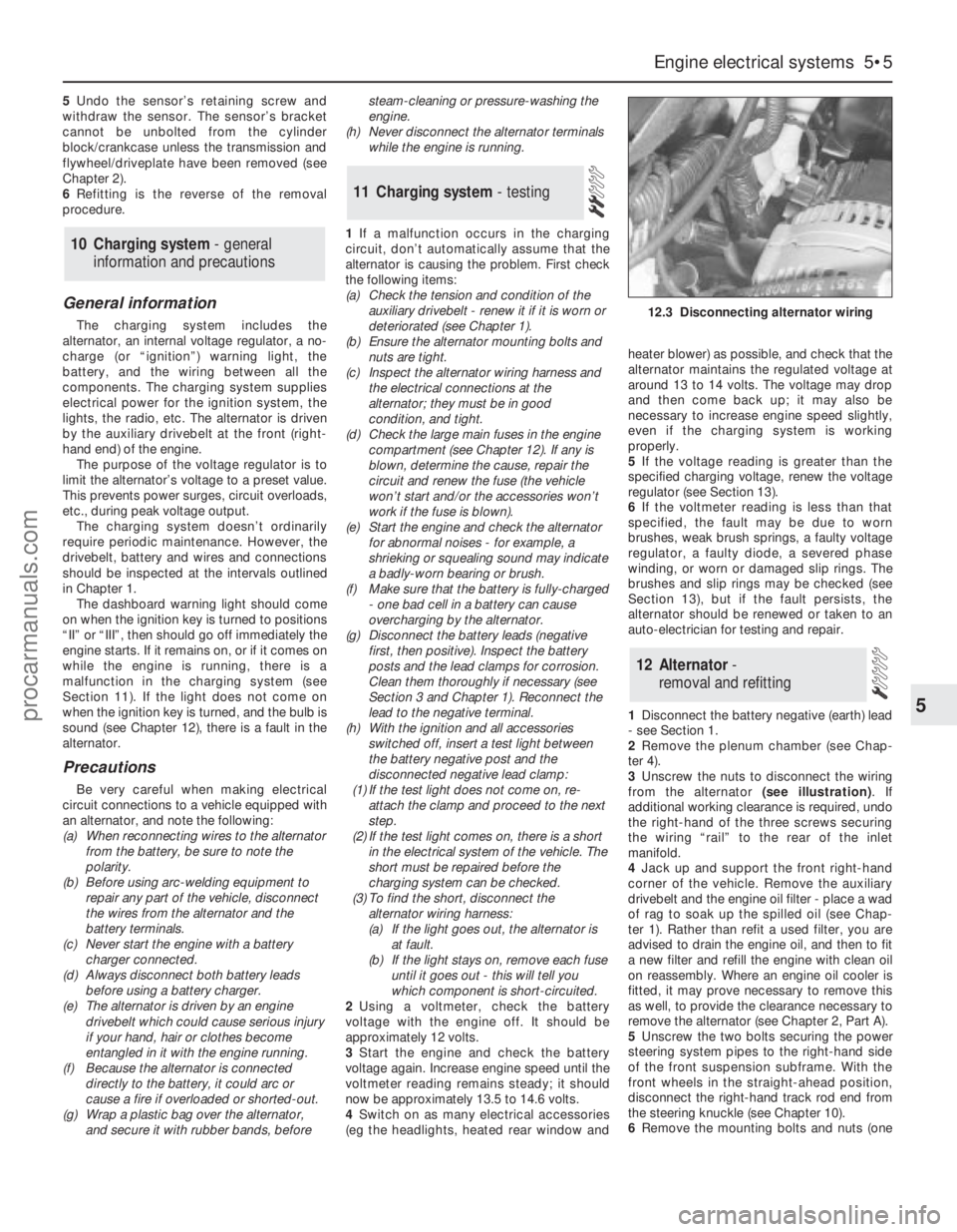
3Unscrew the nuts to disconnect the wiring
from the alternator (see illustration). If
additional working clearance is required, undo
the right-hand of the three screws securing
the wiring “rail” to the rear of the inlet
manifold.
4Jack up and support the front right-hand
corner of the vehicle. Remove the auxiliary
drivebelt and the engine oil filter - place a wad
of rag to soak up the spilled oil (see Chap-
ter 1). Rather than refit a used filter, you are
advised to drain the engine oil, and then to fit
a new filter and refill the engine with clean oil
on reassembly. Where an engine oil cooler is
fitted, it may prove necessary to remove this
as well, to provide the clearance necessary to
remove the alternator (see Chapter 2, Part A).
5Unscrew the two bolts securing the power
steering system pipes to the right-hand side
of the front suspension subframe. With the
front wheels in the straight-ahead position,
disconnect the right-hand track rod end from
the steering knuckle (see Chapter 10).
6Remove the mounting bolts and nuts (one
12 Alternator-
removal and refitting
11 Charging system- testing
10 Charging system - general
information and precautions
Engine electrical systems 5•5
5
12.3 Disconnecting alternator wiring
procarmanuals.com
Page 203 of 279
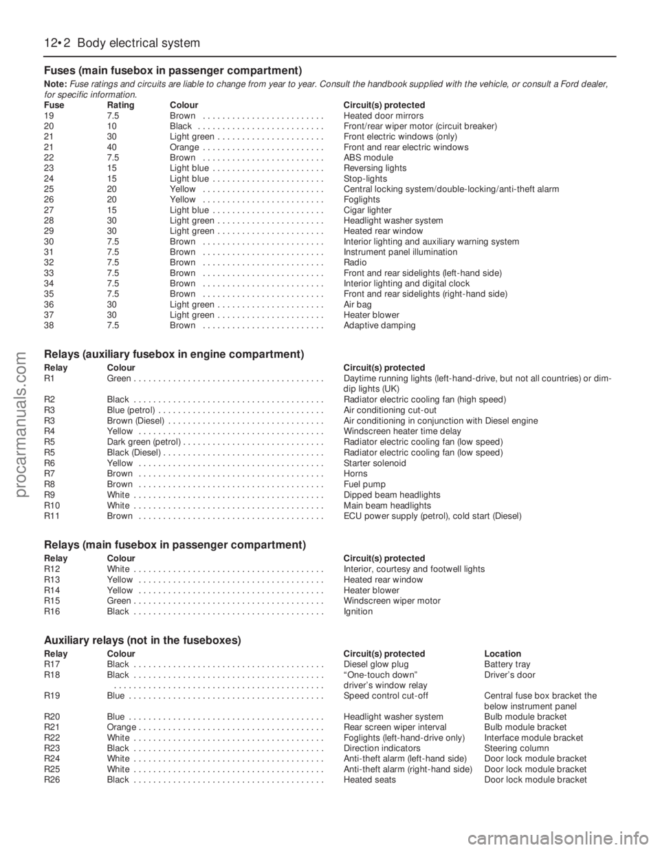
Fuses (main fusebox in passenger compartment)
Note:Fuse ratings and circuits are liable to change from year to year. Consult the handbook supplied with the vehicle, or consult a Ford dealer,
for specific information.
Fuse Rating Colour Circuit(s) protected
19 7.5 Brown . . . . . . . . . . . . . . . . . . . . . . . . . Heated door mirrors
20 10 Black . . . . . . . . . . . . . . . . . . . . . . . . . . Front/rear wiper motor (circuit breaker)
21 30 Light green . . . . . . . . . . . . . . . . . . . . . . Front electric windows (only)
21 40 Orange . . . . . . . . . . . . . . . . . . . . . . . . . Front and rear electric windows
22 7.5 Brown . . . . . . . . . . . . . . . . . . . . . . . . . ABS module
23 15 Light blue . . . . . . . . . . . . . . . . . . . . . . . Reversing lights
24 15 Light blue . . . . . . . . . . . . . . . . . . . . . . . Stop-lights
25 20 Yellow . . . . . . . . . . . . . . . . . . . . . . . . . Central locking system/double-locking/anti-theft alarm
26 20 Yellow . . . . . . . . . . . . . . . . . . . . . . . . . Foglights
27 15 Light blue . . . . . . . . . . . . . . . . . . . . . . . Cigar lighter
28 30 Light green . . . . . . . . . . . . . . . . . . . . . . Headlight washer system
29 30 Light green . . . . . . . . . . . . . . . . . . . . . . Heated rear window
30 7.5 Brown . . . . . . . . . . . . . . . . . . . . . . . . . Interior lighting and auxiliary warning system
31 7.5 Brown . . . . . . . . . . . . . . . . . . . . . . . . . Instrument panel illumination
32 7.5 Brown . . . . . . . . . . . . . . . . . . . . . . . . . Radio
33 7.5 Brown . . . . . . . . . . . . . . . . . . . . . . . . . Front and rear sidelights (left-hand side)
34 7.5 Brown . . . . . . . . . . . . . . . . . . . . . . . . . Interior lighting and digital clock
35 7.5 Brown . . . . . . . . . . . . . . . . . . . . . . . . . Front and rear sidelights (right-hand side)
36 30 Light green . . . . . . . . . . . . . . . . . . . . . . Air bag
37 30 Light green . . . . . . . . . . . . . . . . . . . . . . Heater blower
38 7.5 Brown . . . . . . . . . . . . . . . . . . . . . . . . . Adaptive damping
Relays (auxiliary fusebox in engine compartment)
Relay Colour Circuit(s) protected
R1 Green . . . . . . . . . . . . . . . . . . . . . . . . . . . . . . . . . . . . . . . Daytime running lights (left-hand-drive, but not all countries) or dim-
dip lights (UK)
R2 Black . . . . . . . . . . . . . . . . . . . . . . . . . . . . . . . . . . . . . . . Radiator electric cooling fan (high speed)
R3 Blue (petrol) . . . . . . . . . . . . . . . . . . . . . . . . . . . . . . . . . . Air conditioning cut-out
R3 Brown (Diesel) . . . . . . . . . . . . . . . . . . . . . . . . . . . . . . . . Air conditioning in conjunction with Diesel engine
R4 Yellow . . . . . . . . . . . . . . . . . . . . . . . . . . . . . . . . . . . . . . Windscreen heater time delay
R5 Dark green (petrol) . . . . . . . . . . . . . . . . . . . . . . . . . . . . . Radiator electric cooling fan (low speed)
R5 Black (Diesel) . . . . . . . . . . . . . . . . . . . . . . . . . . . . . . . . . Radiator electric cooling fan (low speed)
R6 Yellow . . . . . . . . . . . . . . . . . . . . . . . . . . . . . . . . . . . . . . Starter solenoid
R7 Brown . . . . . . . . . . . . . . . . . . . . . . . . . . . . . . . . . . . . . . Horns
R8 Brown . . . . . . . . . . . . . . . . . . . . . . . . . . . . . . . . . . . . . . Fuel pump
R9 White . . . . . . . . . . . . . . . . . . . . . . . . . . . . . . . . . . . . . . . Dipped beam headlights
R10 White . . . . . . . . . . . . . . . . . . . . . . . . . . . . . . . . . . . . . . . Main beam headlights
R11 Brown . . . . . . . . . . . . . . . . . . . . . . . . . . . . . . . . . . . . . . ECU power supply (petrol), cold start (Diesel)
Relays (main fusebox in passenger compartment)
Relay Colour Circuit(s) protected
R12 White . . . . . . . . . . . . . . . . . . . . . . . . . . . . . . . . . . . . . . . Interior, courtesy and footwell lights
R13 Yellow . . . . . . . . . . . . . . . . . . . . . . . . . . . . . . . . . . . . . . Heated rear window
R14 Yellow . . . . . . . . . . . . . . . . . . . . . . . . . . . . . . . . . . . . . . Heater blower
R15 Green . . . . . . . . . . . . . . . . . . . . . . . . . . . . . . . . . . . . . . . Windscreen wiper motor
R16 Black . . . . . . . . . . . . . . . . . . . . . . . . . . . . . . . . . . . . . . . Ignition
Auxiliary relays (not in the fuseboxes)
Relay Colour Circuit(s) protected Location
R17 Black . . . . . . . . . . . . . . . . . . . . . . . . . . . . . . . . . . . . . . . Diesel glow plug Battery tray
R18 Black . . . . . . . . . . . . . . . . . . . . . . . . . . . . . . . . . . . . . . . “One-touch down” Driver’s door
. . . . . . . . . . . . . . . . . . . . . . . . . . . . . . . . . . . . . . . . . . . driver’s window relay
R19 Blue . . . . . . . . . . . . . . . . . . . . . . . . . . . . . . . . . . . . . . . . Speed control cut-off Central fuse box bracket the
below instrument panel
R20 Blue . . . . . . . . . . . . . . . . . . . . . . . . . . . . . . . . . . . . . . . . Headlight washer system Bulb module bracket
R21 Orange . . . . . . . . . . . . . . . . . . . . . . . . . . . . . . . . . . . . . . Rear screen wiper interval Bulb module bracket
R22 White . . . . . . . . . . . . . . . . . . . . . . . . . . . . . . . . . . . . . . . Foglights (left-hand-drive only) Interface module bracket
R23 Black . . . . . . . . . . . . . . . . . . . . . . . . . . . . . . . . . . . . . . . Direction indicators Steering column
R24 White . . . . . . . . . . . . . . . . . . . . . . . . . . . . . . . . . . . . . . . Anti-theft alarm (left-hand side) Door lock module bracket
R25 White . . . . . . . . . . . . . . . . . . . . . . . . . . . . . . . . . . . . . . . Anti-theft alarm (right-hand side) Door lock module bracket
R26 Black . . . . . . . . . . . . . . . . . . . . . . . . . . . . . . . . . . . . . . . Heated seats Door lock module bracket
12•2 Body electrical system
procarmanuals.com
Page 205 of 279
compartment, but on Estate models, it is on
the right-hand side.
Some models are fitted with a headlight
levelling system, which is controlled by a knob
on the facia. On position “0”, the headlights
are in their base position, and on position “5”,
the headlights are in their maximum inclined
angle.
It should be noted that, when portions of
the electrical system are serviced, the cable
should be disconnected from the battery
negative terminal, to prevent electrical shorts
and fires.
Caution: When disconnecting the
battery for work described in the
following Sections, refer to
Chapter 5, Section 1.
Note:Refer to the precautions given in
“Safety first!” and in Section 1 of this Chapter
before starting work. The following tests relate
to testing of the main electrical circuits, and
should not be used to test delicate electronic
circuits (such as engine management systems,
anti-lock braking systems, etc), particularly
where an electronic control module is used.
Also refer to the precautions given in Chapter
5, Section 1.
General
1A typical electrical circuit consists of an
electrical component, any switches, relays,
motors, fuses, fusible links or circuit breakers
related to that component, and the wiring and
connectors which link the component to both
the battery and the chassis. To help to
pinpoint a problem in an electrical circuit,
wiring diagrams are included at the end of this
manual.
2Before attempting to diagnose an electrical
fault, first study the appropriate wiring
diagram, to obtain a complete understanding
of the components included in the particular
circuit concerned. The possible sources of a
fault can be narrowed down by noting if other
components related to the circuit are
operating properly. If several components or
circuits fail at one time, the problem is likely to
be related to a shared fuse or earth
connection.
3Electrical problems usually stem from
simple causes, such as loose or corroded
connections, a faulty earth connection, a
blown fuse, a melted fusible link, or a faulty
relay (refer to Section 3 for details of testing
relays). Visually inspect the condition of all
fuses, wires and connections in a problem
circuit before testing the components. Use
the wiring diagrams to determine which
terminal connections will need to be checked
in order to pinpoint the trouble-spot.
4The basic tools required for electrical fault-
finding include a circuit tester or voltmeter (a
12-volt bulb with a set of test leads can alsobe used for certain tests); an ohmmeter (to
measure resistance and check for continuity);
a battery and set of test leads; and a jumper
wire, preferably with a circuit breaker or fuse
incorporated, which can be used to bypass
suspect wires or electrical components.
Before attempting to locate a problem with
test instruments, use the wiring diagram to
determine where to make the connections.
5To find the source of an intermittent wiring
fault (usually due to a poor or dirty
connection, or damaged wiring insulation), a
“wiggle” test can be performed on the wiring.
This involves wiggling the wiring by hand to
see if the fault occurs as the wiring is moved.
It should be possible to narrow down the
source of the fault to a particular section of
wiring. This method of testing can be used in
conjunction with any of the tests described in
the following sub-Sections.
6Apart from problems due to poor
connections, two basic types of fault can
occur in an electrical circuit - open-circuit, or
short-circuit.
7Open-circuit faults are caused by a break
somewhere in the circuit, which prevents
current from flowing. An open-circuit fault will
prevent a component from working.
8Short-circuit faults are caused by a “short”
somewhere in the circuit, which allows the
current flowing in the circuit to “escape” along
an alternative route, usually to earth. Short-
circuit faults are normally caused by a
breakdown in wiring insulation, which allows a
feed wire to touch either another wire, or an
earthed component such as the bodyshell. A
short-circuit fault will normally cause the
relevant circuit fuse to blow.
Finding an open-circuit
9To check for an open-circuit, connect one
lead of a circuit tester or the negative lead of a
voltmeter either to the battery negative
terminal or to a known good earth.
10Connect the other lead to a connector in
the circuit being tested, preferably nearest to
the battery or fuse. At this point, battery
voltage should be present, unless the lead
from the battery or the fuse itself is faulty
(bearing in mind that some circuits are live
only when the ignition switch is moved to a
particular position).
11Switch on the circuit, then connect the
tester lead to the connector nearest the circuit
switch on the component side.
12If voltage is present (indicated either by
the tester bulb lighting or a voltmeter reading,
as applicable), this means that the section of
the circuit between the relevant connector
and the switch is problem-free.
13Continue to check the remainder of the
circuit in the same fashion.
14When a point is reached at which no
voltage is present, the problem must lie
between that point and the previous test point
with voltage. Most problems can be traced to
a broken, corroded or loose connection.
Finding a short-circuit
15To check for a short-circuit, first
disconnect the load(s) from the circuit (loads
are the components which draw current from
a circuit, such as bulbs, motors, heating
elements, etc).
16Remove the relevant fuse from the circuit,
and connect a circuit tester or voltmeter to the
fuse connections.
17Switch on the circuit, bearing in mind that
some circuits are live only when the ignition
switch is moved to a particular position.
18If voltage is present (indicated either by
the tester bulb lighting or a voltmeter reading,
as applicable), this means that there is a
short-circuit.
19If no voltage is present during this test,
but the fuse still blows with the load(s)
reconnected, this indicates an internal fault in
the load(s).
Finding an earth fault
20The battery negative terminal is
connected to “earth” - the metal of the
engine/transmission unit and the vehicle body
- and many systems are wired so that they
only receive a positive feed, the current
returning via the metal of the car body. This
means that the component mounting and the
body form part of that circuit. Loose or
corroded mountings can therefore cause a
range of electrical faults, ranging from total
failure of a circuit, to a puzzling partial failure.
In particular, lights may shine dimly (especially
when another circuit sharing the same earth
point is in operation), motors (eg wiper motors
or the radiator cooling fan motor) may run
slowly, and the operation of one circuit may
have an apparently-unrelated effect on
another. Note that on many vehicles, earth
straps are used between certain components,
such as the engine/transmission and the
body, usually where there is no metal-to-
metal contact between components, due to
flexible rubber mountings, etc.
21To check whether a component is
properly earthed, disconnect the battery (refer
to Chapter 5, Section 1) and connect one lead
of an ohmmeter to a known good earth point.
Connect the other lead to the wire or earth
connection being tested. The resistance
reading should be zero; if not, check the
connection as follows.
22If an earth connection is thought to be
faulty, dismantle the connection, and clean
both the bodyshell and the wire terminal (or
the component earth connection mating
surface) back to bare metal. Be careful to
remove all traces of dirt and corrosion, then
use a knife to trim away any paint, so that a
clean metal-to-metal joint is made. On
reassembly, tighten the joint fasteners
securely; if a wire terminal is being refitted,
use serrated washers between the terminal
and the bodyshell, to ensure a clean and
secure connection. When the connection is
2 Electrical fault finding -
general information
12•4 Body electrical system
procarmanuals.com
Page 209 of 279
Heated windscreen switch and heated
rear window switch
48Disconnect the battery negative (earth)
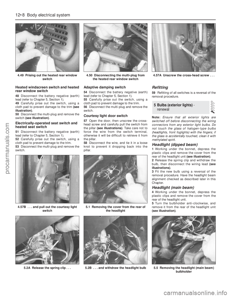
lead (refer to Chapter 5, Section 1).
49Carefully prise out the switch, using a
cloth pad to prevent damage to the trim (see
illustration).
50Disconnect the multi-plug and remove the
switch (see illustration).
Electrically-operated seat switch and
heated seat switch
51Disconnect the battery negative (earth)
lead (refer to Chapter 5, Section 1).
52Carefully prise out the switch, using a
cloth pad to prevent damage to the trim.
53Disconnect the multi-plug and remove the
switch.
Adaptive damping switch
54Disconnect the battery negative (earth)
lead (refer to Chapter 5, Section 1).
55Carefully prise out the switch, using a
cloth pad to prevent damage to the trim.
56Disconnect the multi-plug and remove the
switch.
Courtesy light door switch
57Open the door, then unscrew the cross-
head screw and carefully pull the switch from
the pillar (see illustrations). Take care not to
force the wire from the switch terminal,
otherwise it will be difficult to retrieve it from
the pillar.
58Disconnect the wire, and tie it in a loose
knot to prevent it dropping back into the
pillar.
Refitting
59Refitting of all switches is a reversal of the
removal procedure.
Note:Ensure that all exterior lights are
switched off before disconnecting the wiring
connectors from any exterior light bulbs. Do
not touch the glass of halogen-type bulbs
(headlights, front foglights) with the fingers; if
the glass is accidentally touched, clean it with
methylated spirit.
Headlight (dipped beam)
1Working under the bonnet, depress the
plastic clips and remove the cover from the
rear of the headlight unit (see illustration).
2Release the spring clip and withdraw the
bulb, then disconnect the wiring lead (see
illustrations).
3Fit the new bulb using a reversal of the
removal procedure. Have the headlight beam
alignment checked as described later in this
Chapter.
Headlight (main beam)
4Working under the bonnet, depress the
plastic clips and remove the cover from the
rear of the headlight unit.
5Turn the bulbholder anti-clockwise, and
remove it from the rear of the headlight unit
(see illustration).
5 Bulbs (exterior lights) -
renewal
12•8 Body electrical system
4.49 Prising out the heated rear window
switch4.50 Disconnecting the multi-plug from
the heated rear window switch4.57A Unscrew the cross-head screw . . .
5.2A Release the spring clip . . .5.2B . . . and withdraw the headlight bulb
4.57B . . . and pull out the courtesy light
switch5.1 Removing the cover from the rear of
the headlight
5.5 Removing the headlight (main beam)
bulbholder
procarmanuals.com
Page 213 of 279
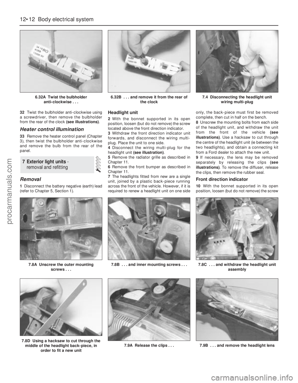
32Twist the bulbholder anti-clockwise using
a screwdriver, then remove the bulbholder
from the rear of the clock (see illustrations).
Heater control illumination
33Remove the heater control panel (Chapter
3), then twist the bulbholder anti-clockwise
and remove the bulb from the rear of the
panel.
Removal
1Disconnect the battery negative (earth) lead
(refer to Chapter 5, Section 1).
Headlight unit
2With the bonnet supported in its open
position, loosen (but do not remove) the screw
located above the front direction indicator.
3Withdraw the front direction indicator unit
forwards, and disconnect the wiring multi-
plug. Place the unit to one side.
4Disconnect the wiring multi-plug for the
headlight unit (see illustration).
5Remove the radiator grille as described in
Chapter 11.
6Remove the front bumper as described in
Chapter 11.
7The headlights fitted from new are a single
unit, joined by a plastic back-piece running
across the front of the vehicle. However, if it is
required to renew a headlight unit on one sideonly, the back-piece must first be removed
complete, then cut in half on the bench.
8Unscrew the mounting bolts from each side
of the headlight unit, and withdraw the unit
from the front of the vehicle (see
illustrations). Use a hacksaw to cut through
the centre of the headlight unit (ie between the
two headlights), and obtain a connecting kit
from a Ford dealer to attach the new unit.
9If necessary, the lens may be removed
separately by releasing the clips (see
illustrations). To remove the diffuser, release
the clips, then remove the rubber seal.
Front direction indicator
10With the bonnet supported in its open
position, loosen (but do not remove) the screw
7 Exterior light units -
removal and refitting
12•12 Body electrical system
6.32A Twist the bulbholder
anti-clockwise . . .6.32B . . . and remove it from the rear of
the clock7.4 Disconnecting the headlight unit
wiring multi-plug
7.8D Using a hacksaw to cut through the
middle of the headlight back-piece, in
order to fit a new unit7.9A Release the clips . . .7.9B . . . and remove the headlight lens
7.8A Unscrew the outer mounting
screws . . .7.8B . . . and inner mounting screws . . .7.8C . . . and withdraw the headlight unit
assembly
procarmanuals.com
Page 214 of 279
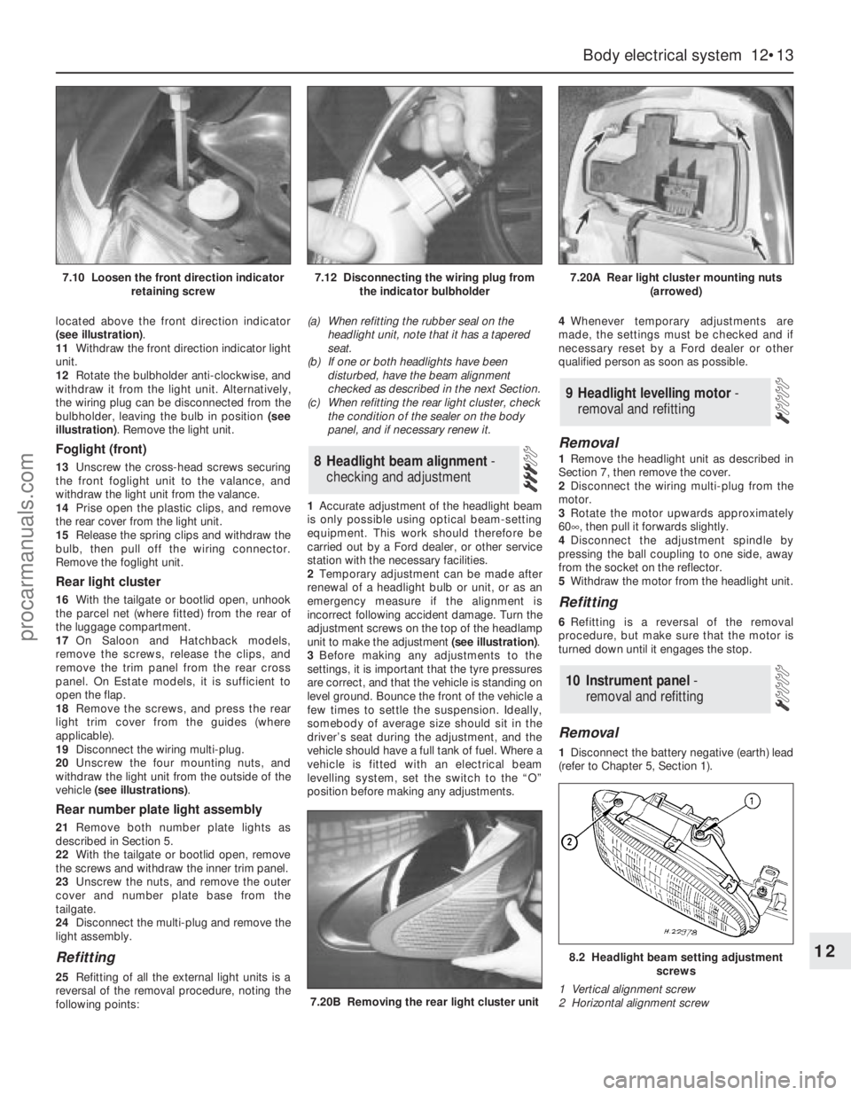
located above the front direction indicator
(see illustration).
11Withdraw the front direction indicator light
unit.
12Rotate the bulbholder anti-clockwise, and
withdraw it from the light unit. Alternatively,
the wiring plug can be disconnected from the
bulbholder, leaving the bulb in position (see
illustration). Remove the light unit.
Foglight (front)
13Unscrew the cross-head screws securing
the front foglight unit to the valance, and
withdraw the light unit from the valance.
14Prise open the plastic clips, and remove
the rear cover from the light unit.
15Release the spring clips and withdraw the
bulb, then pull off the wiring connector.
Remove the foglight unit.
Rear light cluster
16With the tailgate or bootlid open, unhook
the parcel net (where fitted) from the rear of
the luggage compartment.
17On Saloon and Hatchback models,
remove the screws, release the clips, and
remove the trim panel from the rear cross
panel. On Estate models, it is sufficient to
open the flap.
18Remove the screws, and press the rear
light trim cover from the guides (where
applicable).
19Disconnect the wiring multi-plug.
20Unscrew the four mounting nuts, and
withdraw the light unit from the outside of the
vehicle (see illustrations).
Rear number plate light assembly
21Remove both number plate lights as
described in Section 5.
22With the tailgate or bootlid open, remove
the screws and withdraw the inner trim panel.
23Unscrew the nuts, and remove the outer
cover and number plate base from the
tailgate.
24Disconnect the multi-plug and remove the
light assembly.
Refitting
25Refitting of all the external light units is a
reversal of the removal procedure, noting the
following points:(a) When refitting the rubber seal on the
headlight unit, note that it has a tapered
seat.
(b) If one or both headlights have been
disturbed, have the beam alignment
checked as described in the next Section.
(c) When refitting the rear light cluster, check
the condition of the sealer on the body
panel, and if necessary renew it.
1Accurate adjustment of the headlight beam
is only possible using optical beam-setting
equipment. This work should therefore be
carried out by a Ford dealer, or other service
station with the necessary facilities.
2Temporary adjustment can be made after
renewal of a headlight bulb or unit, or as an
emergency measure if the alignment is
incorrect following accident damage. Turn the
adjustment screws on the top of the headlamp
unit to make the adjustment (see illustration).
3Before making any adjustments to the
settings, it is important that the tyre pressures
are correct, and that the vehicle is standing on
level ground. Bounce the front of the vehicle a
few times to settle the suspension. Ideally,
somebody of average size should sit in the
driver’s seat during the adjustment, and the
vehicle should have a full tank of fuel. Where a
vehicle is fitted with an electrical beam
levelling system, set the switch to the “O”
position before making any adjustments.4Whenever temporary adjustments are
made, the settings must be checked and if
necessary reset by a Ford dealer or other
qualified person as soon as possible.
Removal
1Remove the headlight unit as described in
Section 7, then remove the cover.
2Disconnect the wiring multi-plug from the
motor.
3Rotate the motor upwards approximately
60°, then pull it forwards slightly.
4Disconnect the adjustment spindle by
pressing the ball coupling to one side, away
from the socket on the reflector.
5Withdraw the motor from the headlight unit.
Refitting
6Refitting is a reversal of the removal
procedure, but make sure that the motor is
turned down until it engages the stop.
Removal
1Disconnect the battery negative (earth) lead
(refer to Chapter 5, Section 1).
10 Instrument panel -
removal and refitting
9 Headlight levelling motor -
removal and refitting
8 Headlight beam alignment-
checking and adjustment
Body electrical system 12•13
12
7.20B Removing the rear light cluster unit
8.2 Headlight beam setting adjustment
screws
1 Vertical alignment screw
2 Horizontal alignment screw
7.10 Loosen the front direction indicator
retaining screw7.12 Disconnecting the wiring plug from
the indicator bulbholder7.20A Rear light cluster mounting nuts
(arrowed)
procarmanuals.com