1993 FORD MONDEO wheel bolt torque
[x] Cancel search: wheel bolt torquePage 27 of 279
amperage charger, but don’t use one rated
more than 1/10th the amp/hour rating of the
battery (ie no more than 5 amps, typically).
Rapid boost charges that claim to restore the
power of the battery in one to two hours are
hardest on the battery, and can damage
batteries not in good condition. This type of
charging should only be used in emergency
situations.
14The average time necessary to charge a
battery should be listed in the instructions that
come with the charger. As a general rule, a
trickle charger will charge a battery in 12 to
16 hours.
1Check the seat belts for satisfactory
operation and condition. Inspect the webbing
for fraying and cuts. Check that they retract
smoothly and without binding into their reels.
2Check that the seat belt mounting bolts are
tight, and if necessary tighten them to the
specified torque wrench setting.
General
1The auxiliary drivebelt is of the flat, multi-
ribbed (or “polyvee”) type, and is located on
the right-hand end of the engine. It drives the
alternator, water pump, power steering pump
and (when fitted) the air conditioning
compressor from the engine’s crankshaft
pulley.
2The good condition and proper tension of
the auxiliary drivebelt is critical to the
operation of the engine. Because of their
composition and the high stresses to which
they are subjected, drivebelts stretch anddeteriorate as they get older. They must,
therefore, be regularly inspected.
Check
3With the engine switched off, open and
support the bonnet, then locate the auxiliary
drivebelt on the right-hand end of the engine,
under the engine right-hand mounting
bracket. (Be very careful, and wear protective
gloves to minimise the risk of burning your
hands on hot components, if the engine has
recently been running.) For improved access,
jack up the front right-hand side of the
vehicle, support it securely on an axle stand,
remove the roadwheel, then remove the
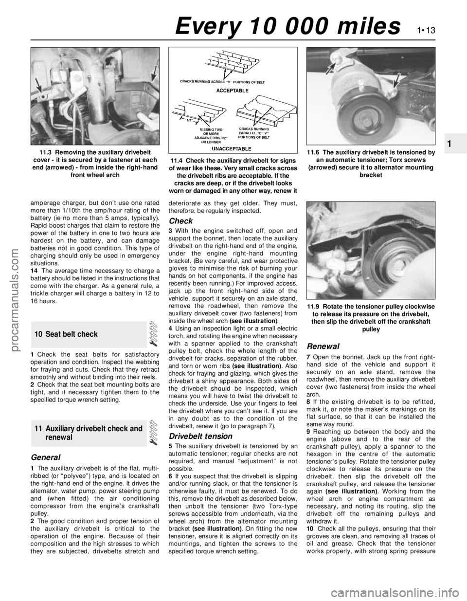
auxiliary drivebelt cover (two fasteners) from
inside the wheel arch (see illustration).
4Using an inspection light or a small electric
torch, and rotating the engine when necessary
with a spanner applied to the crankshaft
pulley bolt, check the whole length of the
drivebelt for cracks, separation of the rubber,
and torn or worn ribs (see illustration). Also
check for fraying and glazing, which gives the
drivebelt a shiny appearance. Both sides of
the drivebelt should be inspected, which
means you will have to twist the drivebelt to
check the underside. Use your fingers to feel
the drivebelt where you can’t see it. If you are
in any doubt as to the condition of the
drivebelt, renew it (go to paragraph 7).
Drivebelt tension
5The auxiliary drivebelt is tensioned by an
automatic tensioner; regular checks are not
required, and manual “adjustment” is not
possible.
6If you suspect that the drivebelt is slipping
and/or running slack, or that the tensioner is
otherwise faulty, it must be renewed. To do
this, remove the drivebelt as described below,
then unbolt the tensioner (two Torx-type
screws accessible from underneath, via the
wheel arch) from the alternator mounting
bracket (see illustration). On fitting the new
tensioner, ensure it is aligned correctly on its
mountings, and tighten the screws to the
specified torque wrench setting.
Renewal
7Open the bonnet. Jack up the front right-
hand side of the vehicle and support it
securely on an axle stand, remove the
roadwheel, then remove the auxiliary drivebelt
cover (two fasteners) from inside the wheel
arch.
8If the existing drivebelt is to be refitted,
mark it, or note the maker’s markings on its
flat surface, so that it can be installed the
same way round.
9Reaching up between the body and the
engine (above and to the rear of the
crankshaft pulley), apply a spanner to the
hexagon in the centre of the automatic
tensioner’s pulley. Rotate the tensioner pulley
clockwise to release its pressure on the
drivebelt, then slip the drivebelt off the
crankshaft pulley, and release the tensioner
again (see illustration). Working from the
wheel arch or engine compartment as
necessary, and noting its routing, slip the
drivebelt off the remaining pulleys and
withdraw it.
10Check all the pulleys, ensuring that their
grooves are clean, and removing all traces of
oil and grease. Check that the tensioner
works properly, with strong spring pressure
11 Auxiliary drivebelt check and
renewal
10 Seat belt check
1•13
1
11.9 Rotate the tensioner pulley clockwise
to release its pressure on the drivebelt,
then slip the drivebelt off the crankshaft
pulley
11.3 Removing the auxiliary drivebelt
cover - it is secured by a fastener at each
end (arrowed) - from inside the right-hand
front wheel arch
11.4 Check the auxiliary drivebelt for signs
of wear like these. Very small cracks across
the drivebelt ribs are acceptable. If the
cracks are deep, or if the drivebelt looks
worn or damaged in any other way, renew it
11.6 The auxiliary drivebelt is tensioned by
an automatic tensioner; Torx screws
(arrowed) secure it to alternator mounting
bracket
Every 10 000 miles
procarmanuals.com
Page 34 of 279
brake shoes is not less than the
recommendation given in the Specifications.
14If it is difficult to determine the exact
thickness of the brake shoe linings, or if you
are at all concerned about the condition of the
shoes, then remove the rear drums for a more
comprehensive inspection (refer to Chapter 9)
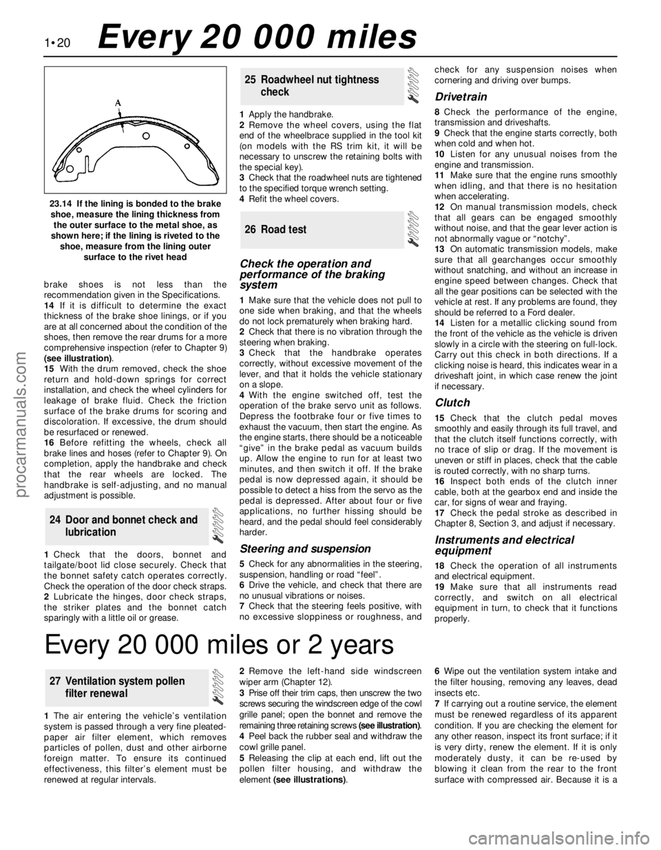
(see illustration).
15With the drum removed, check the shoe
return and hold-down springs for correct
installation, and check the wheel cylinders for
leakage of brake fluid. Check the friction
surface of the brake drums for scoring and
discoloration. If excessive, the drum should
be resurfaced or renewed.
16Before refitting the wheels, check all
brake lines and hoses (refer to Chapter 9). On
completion, apply the handbrake and check
that the rear wheels are locked. The
handbrake is self-adjusting, and no manual
adjustment is possible.
1Check that the doors, bonnet and
tailgate/boot lid close securely. Check that
the bonnet safety catch operates correctly.
Check the operation of the door check straps.
2Lubricate the hinges, door check straps,
the striker plates and the bonnet catch
sparingly with a little oil or grease.1Apply the handbrake.
2Remove the wheel covers, using the flat
end of the wheelbrace supplied in the tool kit
(on models with the RS trim kit, it will be
necessary to unscrew the retaining bolts with
the special key).
3Check that the roadwheel nuts are tightened
to the specified torque wrench setting.
4Refit the wheel covers.
Check the operation and
performance of the braking
system
1Make sure that the vehicle does not pull to
one side when braking, and that the wheels
do not lock prematurely when braking hard.
2Check that there is no vibration through the
steering when braking.
3Check that the handbrake operates
correctly, without excessive movement of the
lever, and that it holds the vehicle stationary
on a slope.
4With the engine switched off, test the
operation of the brake servo unit as follows.
Depress the footbrake four or five times to
exhaust the vacuum, then start the engine. As
the engine starts, there should be a noticeable
“give” in the brake pedal as vacuum builds
up. Allow the engine to run for at least two
minutes, and then switch it off. If the brake
pedal is now depressed again, it should be
possible to detect a hiss from the servo as the
pedal is depressed. After about four or five
applications, no further hissing should be
heard, and the pedal should feel considerably
harder.
Steering and suspension
5Check for any abnormalities in the steering,
suspension, handling or road “feel”.
6Drive the vehicle, and check that there are
no unusual vibrations or noises.
7Check that the steering feels positive, with
no excessive sloppiness or roughness, andcheck for any suspension noises when
cornering and driving over bumps.
Drivetrain
8Check the performance of the engine,
transmission and driveshafts.
9Check that the engine starts correctly, both
when cold and when hot.
10Listen for any unusual noises from the
engine and transmission.
11Make sure that the engine runs smoothly
when idling, and that there is no hesitation
when accelerating.
12On manual transmission models, check
that all gears can be engaged smoothly
without noise, and that the gear lever action is
not abnormally vague or “notchy”.
13On automatic transmission models, make
sure that all gearchanges occur smoothly
without snatching, and without an increase in
engine speed between changes. Check that
all the gear positions can be selected with the
vehicle at rest. If any problems are found, they
should be referred to a Ford dealer.
14Listen for a metallic clicking sound from
the front of the vehicle as the vehicle is driven
slowly in a circle with the steering on full-lock.
Carry out this check in both directions. If a
clicking noise is heard, this indicates wear in a
driveshaft joint, in which case renew the joint
if necessary.
Clutch
15Check that the clutch pedal moves
smoothly and easily through its full travel, and
that the clutch itself functions correctly, with
no trace of slip or drag. If the movement is
uneven or stiff in places, check that the cable
is routed correctly, with no sharp turns.
16Inspect both ends of the clutch inner
cable, both at the gearbox end and inside the
car, for signs of wear and fraying.
17Check the pedal stroke as described in
Chapter 8, Section 3, and adjust if necessary.
Instruments and electrical
equipment
18Check the operation of all instruments
and electrical equipment.
19Make sure that all instruments read
correctly, and switch on all electrical
equipment in turn, to check that it functions
properly.
26 Road test
25 Roadwheel nut tightness
check
24 Door and bonnet check and
lubrication
1•20
23.14 If the lining is bonded to the brake
shoe, measure the lining thickness from
the outer surface to the metal shoe, as
shown here; if the lining is riveted to the
shoe, measure from the lining outer
surface to the rivet head
Every 20 000 miles
Every 20 000 miles or 2 years
1The air entering the vehicle’s ventilation
system is passed through a very fine pleated-
paper air filter element, which removes
particles of pollen, dust and other airborne
foreign matter. To ensure its continued
effectiveness, this filter’s element must be
renewed at regular intervals.2Remove the left-hand side windscreen
wiper arm (Chapter 12).
3Prise off their trim caps, then unscrew the two
screws securing the windscreen edge of the cowl
grille panel; open the bonnet and remove the
remaining three retaining screws (see illustration).
4Peel back the rubber seal and withdraw the
cowl grille panel.
5Releasing the clip at each end, lift out the
pollen filter housing, and withdraw the
element (see illustrations).6Wipe out the ventilation system intake and
the filter housing, removing any leaves, dead
insects etc.
7If carrying out a routine service, the element
must be renewed regardless of its apparent
condition. If you are checking the element for
any other reason, inspect its front surface; if it
is very dirty, renew the element. If it is only
moderately dusty, it can be re-used by
blowing it clean from the rear to the front
surface with compressed air. Because it is a
27 Ventilation system pollen
filter renewal
procarmanuals.com
Page 42 of 279
Lubrication
Engine oil type/specification . . . . . . . . . . . . . . . . . . . . . . . . . . . . . . . . . . See Chapter 1
Engine oil capacity . . . . . . . . . . . . . . . . . . . . . . . . . . . . . . . . . . . . . . . . . See Chapter 1
Oil pressure . . . . . . . . . . . . . . . . . . . . . . . . . . . . . . . . . . . . . . . . . . . . . . . No information available at time of writing
Oil pump clearances . . . . . . . . . . . . . . . . . . . . . . . . . . . . . . . . . . . . . . . . No information available at time of writing
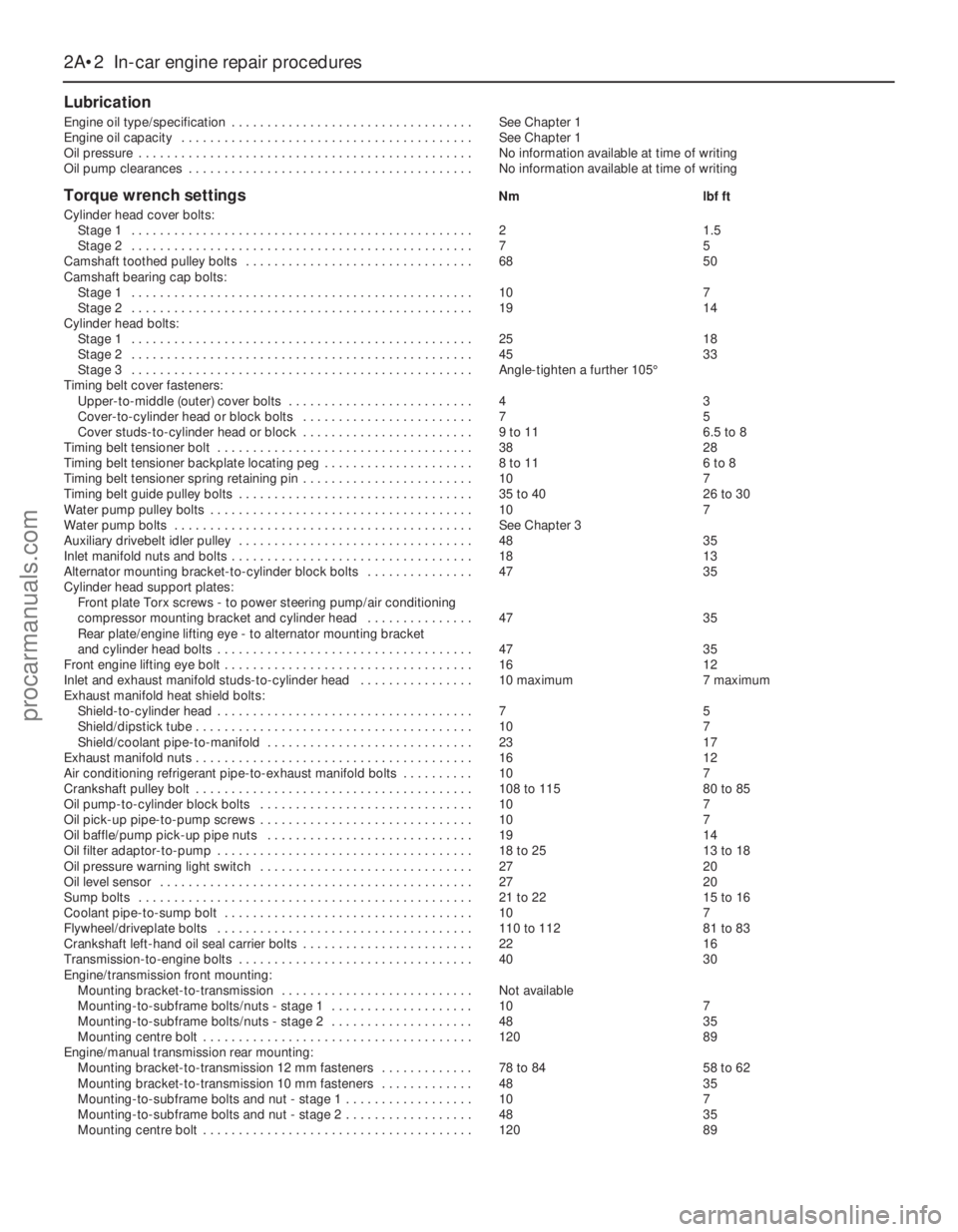
Torque wrench settingsNm lbf ft
Cylinder head cover bolts:
Stage 1 . . . . . . . . . . . . . . . . . . . . . . . . . . . . . . . . . . . . . . . . . . . . . . . . 2 1.5
Stage 2 . . . . . . . . . . . . . . . . . . . . . . . . . . . . . . . . . . . . . . . . . . . . . . . . 7 5
Camshaft toothed pulley bolts . . . . . . . . . . . . . . . . . . . . . . . . . . . . . . . . 68 50
Camshaft bearing cap bolts:
Stage 1 . . . . . . . . . . . . . . . . . . . . . . . . . . . . . . . . . . . . . . . . . . . . . . . . 10 7
Stage 2 . . . . . . . . . . . . . . . . . . . . . . . . . . . . . . . . . . . . . . . . . . . . . . . . 19 14
Cylinder head bolts:
Stage 1 . . . . . . . . . . . . . . . . . . . . . . . . . . . . . . . . . . . . . . . . . . . . . . . . 25 18
Stage 2 . . . . . . . . . . . . . . . . . . . . . . . . . . . . . . . . . . . . . . . . . . . . . . . . 45 33
Stage 3 . . . . . . . . . . . . . . . . . . . . . . . . . . . . . . . . . . . . . . . . . . . . . . . . Angle-tighten a further 105°
Timing belt cover fasteners:
Upper-to-middle (outer) cover bolts . . . . . . . . . . . . . . . . . . . . . . . . . . 4 3
Cover-to-cylinder head or block bolts . . . . . . . . . . . . . . . . . . . . . . . . 7 5
Cover studs-to-cylinder head or block . . . . . . . . . . . . . . . . . . . . . . . . 9 to 11 6.5 to 8
Timing belt tensioner bolt . . . . . . . . . . . . . . . . . . . . . . . . . . . . . . . . . . . . 38 28
Timing belt tensioner backplate locating peg . . . . . . . . . . . . . . . . . . . . . 8 to 11 6 to 8
Timing belt tensioner spring retaining pin . . . . . . . . . . . . . . . . . . . . . . . . 10 7
Timing belt guide pulley bolts . . . . . . . . . . . . . . . . . . . . . . . . . . . . . . . . . 35 to 40 26 to 30
Water pump pulley bolts . . . . . . . . . . . . . . . . . . . . . . . . . . . . . . . . . . . . . 10 7
Water pump bolts . . . . . . . . . . . . . . . . . . . . . . . . . . . . . . . . . . . . . . . . . . See Chapter 3
Auxiliary drivebelt idler pulley . . . . . . . . . . . . . . . . . . . . . . . . . . . . . . . . . 48 35
Inlet manifold nuts and bolts . . . . . . . . . . . . . . . . . . . . . . . . . . . . . . . . . . 18 13
Alternator mounting bracket-to-cylinder block bolts . . . . . . . . . . . . . . . 47 35
Cylinder head support plates:
Front plate Torx screws - to power steering pump/air conditioning
compressor mounting bracket and cylinder head . . . . . . . . . . . . . . . 47 35
Rear plate/engine lifting eye - to alternator mounting bracket
and cylinder head bolts . . . . . . . . . . . . . . . . . . . . . . . . . . . . . . . . . . . . 47 35
Front engine lifting eye bolt . . . . . . . . . . . . . . . . . . . . . . . . . . . . . . . . . . . 16 12
Inlet and exhaust manifold studs-to-cylinder head . . . . . . . . . . . . . . . . 10 maximum 7 maximum
Exhaust manifold heat shield bolts:
Shield-to-cylinder head . . . . . . . . . . . . . . . . . . . . . . . . . . . . . . . . . . . . 7 5
Shield/dipstick tube . . . . . . . . . . . . . . . . . . . . . . . . . . . . . . . . . . . . . . . 10 7
Shield/coolant pipe-to-manifold . . . . . . . . . . . . . . . . . . . . . . . . . . . . . 23 17
Exhaust manifold nuts . . . . . . . . . . . . . . . . . . . . . . . . . . . . . . . . . . . . . . . 16 12
Air conditioning refrigerant pipe-to-exhaust manifold bolts . . . . . . . . . . 10 7
Crankshaft pulley bolt . . . . . . . . . . . . . . . . . . . . . . . . . . . . . . . . . . . . . . . 108 to 115 80 to 85
Oil pump-to-cylinder block bolts . . . . . . . . . . . . . . . . . . . . . . . . . . . . . . 10 7
Oil pick-up pipe-to-pump screws . . . . . . . . . . . . . . . . . . . . . . . . . . . . . . 10 7
Oil baffle/pump pick-up pipe nuts . . . . . . . . . . . . . . . . . . . . . . . . . . . . . 19 14
Oil filter adaptor-to-pump . . . . . . . . . . . . . . . . . . . . . . . . . . . . . . . . . . . . 18 to 25 13 to 18
Oil pressure warning light switch . . . . . . . . . . . . . . . . . . . . . . . . . . . . . . 27 20
Oil level sensor . . . . . . . . . . . . . . . . . . . . . . . . . . . . . . . . . . . . . . . . . . . . 27 20
Sump bolts . . . . . . . . . . . . . . . . . . . . . . . . . . . . . . . . . . . . . . . . . . . . . . . 21 to 22 15 to 16
Coolant pipe-to-sump bolt . . . . . . . . . . . . . . . . . . . . . . . . . . . . . . . . . . . 10 7
Flywheel/driveplate bolts . . . . . . . . . . . . . . . . . . . . . . . . . . . . . . . . . . . . 110 to 112 81 to 83
Crankshaft left-hand oil seal carrier bolts . . . . . . . . . . . . . . . . . . . . . . . . 22 16
Transmission-to-engine bolts . . . . . . . . . . . . . . . . . . . . . . . . . . . . . . . . . 40 30
Engine/transmission front mounting:
Mounting bracket-to-transmission . . . . . . . . . . . . . . . . . . . . . . . . . . . Not available
Mounting-to-subframe bolts/nuts - stage 1 . . . . . . . . . . . . . . . . . . . . 10 7
Mounting-to-subframe bolts/nuts - stage 2 . . . . . . . . . . . . . . . . . . . . 48 35
Mounting centre bolt . . . . . . . . . . . . . . . . . . . . . . . . . . . . . . . . . . . . . . 120 89
Engine/manual transmission rear mounting:
Mounting bracket-to-transmission 12 mm fasteners . . . . . . . . . . . . . 78 to 84 58 to 62
Mounting bracket-to-transmission 10 mm fasteners . . . . . . . . . . . . . 48 35
Mounting-to-subframe bolts and nut - stage 1 . . . . . . . . . . . . . . . . . . 10 7
Mounting-to-subframe bolts and nut - stage 2 . . . . . . . . . . . . . . . . . . 48 35
Mounting centre bolt . . . . . . . . . . . . . . . . . . . . . . . . . . . . . . . . . . . . . . 120 89
2A•2 In-car engine repair procedures
procarmanuals.com
Page 47 of 279
throttle linkage as described in Chapter 4.
Where fitted, disconnect also the cruise
control actuator cable (see Chapter 12).
3Remove the timing belt upper cover (see
Section 9).
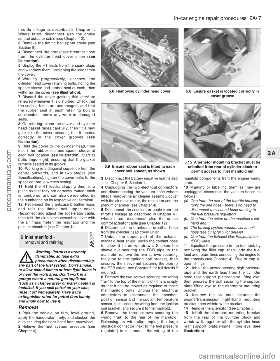
4Disconnect the crankcase breather hose
from the cylinder head cover union (see
illustration).
5Unplug the HT leads from the spark plugs
and withdraw them, unclipping the leads from
the cover.
6Working progressively, unscrew the
cylinder head cover retaining bolts, noting the
spacer sleeve and rubber seal at each, then
withdraw the cover (see illustration).
7Discard the cover gasket; this mustbe
renewed whenever it is disturbed. Check that
the sealing faces are undamaged, and that
the rubber seal at each retaining bolt is
serviceable; renew any worn or damaged
seals.
8On refitting, clean the cover and cylinder
head gasket faces carefully, then fit a new
gasket to the cover, ensuring that it locates
correctly in the cover grooves (see
illustration).
9Refit the cover to the cylinder head, then
insert the rubber seal and spacer sleeve at
each bolt location (see illustration). Start all
bolts finger-tight, ensuring that the gasket
remains seated in its groove.
10Working in a diagonal sequence from the
centre outwards, and in two stages (see
Specifications), tighten the cover bolts to the
specified torque wrench setting.
11Refit the HT leads, clipping them into
place so that they are correctly routed; each
is numbered, and can also be identified by
the numbering on its respective coil terminal.
12Reconnect the crankcase breather hose,
and refit the timing belt upper cover.
Reconnect and adjust the accelerator cable,
then refit the air cleaner assembly cover with
the air mass meter, the resonator and the
plenum chamber (see Chapter 4).
Warning: Petrol is extremely
flammable, so take extra
precautions when disconnecting
any part of the fuel system. Don’t smoke,
or allow naked flames or bare light bulbs in
or near the work area. Don’t work in a
garage where a natural gas appliance
(such as a clothes dryer or water heater) is
installed. If you spill petrol on your skin,
rinse it off immediately. Have a fire
extinguisher rated for petrol fires handy,
and know how to use it.
Removal
1Park the vehicle on firm, level ground,
apply the handbrake firmly, and slacken the
nuts securing the right-hand front roadwheel.
2Relieve the fuel system pressure (see
Chapter 4).3Disconnect the battery negative (earth) lead
- see Chapter 5, Section 1.
4Unplugging the two electrical connectors
and disconnecting the vacuum hose (where
fitted), remove the air cleaner assembly cover
with the air mass meter, the resonator and the
plenum chamber (see Chapter 4).
5Disconnect the accelerator cable from the
throttle linkage as described in Chapter 4 -
where fitted, disconnect also the cruise
control actuator cable (see Chapter 12).
6Disconnect the crankcase breather hose
from the cylinder head cover union.
7Unbolt the upper part of the exhaust
manifold heat shield; unclip the coolant hose
to allow it to be withdrawn. Slacken the
sleeve nut securing the EGR pipe to the
manifold, remove the two screws securing
the pipe to the ignition coil bracket, then
unscrew the sleeve nut securing the pipe to
the EGR valve - see Chapter 6 for full details if
required.
8Remove the two screws securing the wiring
“rail” to the top of the manifold - this is simply
so that it can be moved as required to reach
the manifold bolts. Unplug their electrical
connectors to disconnect the camshaft
position sensor and the coolant temperature
sensor, then unclip the wiring from the ignition
coil bracket, and secure it to the manifold.
9Remove the three screws securing the
wiring “rail” to the rear of the manifold.
Releasing its wire clip, unplug the large
electrical connector (next to the fuel pressure
regulator) to disconnect the wiring of themanifold components from the engine wiring
loom.
10Marking or labelling them as they are
unplugged, disconnect the vacuum hoses as
follows:
(a) One from the rear of the throttle housing
(only the one hose - there is no need to
disconnect the second hose running to
the fuel pressure regulator).
(b) One from the union on the manifold’s left-
hand end.
(c) The braking system vacuum servo unit
hose (see Chapter 9 for details).
(d) One from the Exhaust Gas Recirculation
(EGR) valve.
11Equalise the pressure in the fuel tank by
removing the filler cap, then undo the fuel
feed and return lines connecting the engine to
the chassis (see Chapter 4). Plug or cap all
open fittings.
12Unbolt the power steering high-pressure
pipe and the earth lead from the cylinder
head rear support plate/engine lifting eye,
then unscrew the bolt securing the support
plate/lifting eye to the alternator mounting
bracket.
13Unscrew the six nuts securing the
engine/transmission right-hand mounting
bracket, then withdraw the bracket.
14Remove the alternator (see Chapter 5).
15Unbolt the alternator mounting bracket
from the rear of the cylinder block and
withdraw it, together with the cylinder head
rear support plate/engine lifting eye (see
illustration).
6 Inlet manifold -
removal and refitting
In-car engine repair procedures 2A•7
2A
5.8 Ensure gasket is located correctly in
cover groove5.6 Removing cylinder head cover
5.9 Ensure rubber seal is fitted to each
cover bolt spacer, as shown6.15 Alternator mounting bracket must be
unbolted from rear of cylinder block to
permit access to inlet manifold nut
procarmanuals.com
Page 49 of 279
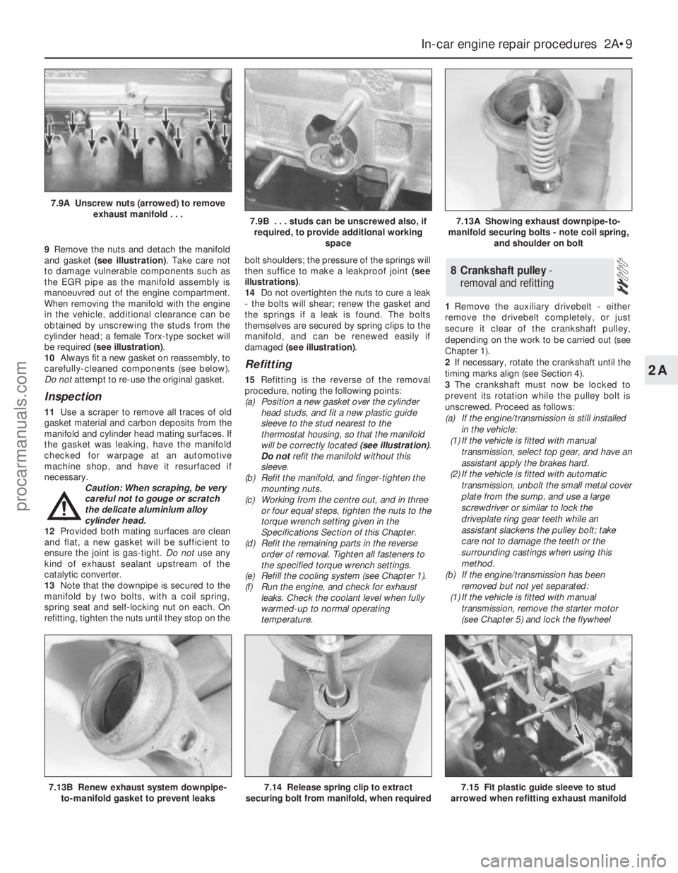
9Remove the nuts and detach the manifold
and gasket (see illustration). Take care not
to damage vulnerable components such as
the EGR pipe as the manifold assembly is
manoeuvred out of the engine compartment.
When removing the manifold with the engine
in the vehicle, additional clearance can be
obtained by unscrewing the studs from the
cylinder head; a female Torx-type socket will
be required (see illustration).
10Always fit a new gasket on reassembly, to
carefully-cleaned components (see below).
Do notattempt to re-use the original gasket.
Inspection
11Use a scraper to remove all traces of old
gasket material and carbon deposits from the
manifold and cylinder head mating surfaces. If
the gasket was leaking, have the manifold
checked for warpage at an automotive
machine shop, and have it resurfaced if
necessary.
Caution: When scraping, be very
careful not to gouge or scratch
the delicate aluminium alloy
cylinder head.
12Provided both mating surfaces are clean
and flat, a new gasket will be sufficient to
ensure the joint is gas-tight. Do notuse any
kind of exhaust sealant upstream of the
catalytic converter.
13Note that the downpipe is secured to the
manifold by two bolts, with a coil spring,
spring seat and self-locking nut on each. On
refitting, tighten the nuts until they stop on thebolt shoulders; the pressure of the springs will
then suffice to make a leakproof joint (see
illustrations).
14Do not overtighten the nuts to cure a leak
- the bolts will shear; renew the gasket and
the springs if a leak is found. The bolts
themselves are secured by spring clips to the
manifold, and can be renewed easily if
damaged (see illustration).
Refitting
15Refitting is the reverse of the removal
procedure, noting the following points:
(a) Position a new gasket over the cylinder
head studs, and fit a new plastic guide
sleeve to the stud nearest to the
thermostat housing, so that the manifold
will be correctly located (see illustration).
Do notrefit the manifold without this
sleeve.
(b) Refit the manifold, and finger-tighten the
mounting nuts.
(c) Working from the centre out, and in three
or four equal steps, tighten the nuts to the
torque wrench setting given in the
Specifications Section of this Chapter.
(d) Refit the remaining parts in the reverse
order of removal. Tighten all fasteners to
the specified torque wrench settings.
(e) Refill the cooling system (see Chapter 1).
(f) Run the engine, and check for exhaust
leaks. Check the coolant level when fully
warmed-up to normal operating
temperature.1Remove the auxiliary drivebelt - either
remove the drivebelt completely, or just
secure it clear of the crankshaft pulley,
depending on the work to be carried out (see
Chapter 1).
2If necessary, rotate the crankshaft until the
timing marks align (see Section 4).
3The crankshaft must now be locked to
prevent its rotation while the pulley bolt is
unscrewed. Proceed as follows:
(a) If the engine/transmission is still installed
in the vehicle:
(1) If the vehicle is fitted with manual
transmission, select top gear, and have an
assistant apply the brakes hard.
(2) If the vehicle is fitted with automatic
transmission, unbolt the small metal cover
plate from the sump, and use a large
screwdriver or similar to lock the
driveplate ring gear teeth while an
assistant slackens the pulley bolt; take
care not to damage the teeth or the
surrounding castings when using this
method.
(b) If the engine/transmission has been
removed but not yet separated:
(1) If the vehicle is fitted with manual
transmission, remove the starter motor
(see Chapter 5) and lock the flywheel
8 Crankshaft pulley -
removal and refitting
In-car engine repair procedures 2A•9
2A
7.13B Renew exhaust system downpipe-
to-manifold gasket to prevent leaks7.14 Release spring clip to extract
securing bolt from manifold, when required7.15 Fit plastic guide sleeve to stud
arrowed when refitting exhaust manifold
7.9A Unscrew nuts (arrowed) to remove
exhaust manifold . . .
7.9B . . . studs can be unscrewed also, if
required, to provide additional working
space7.13A Showing exhaust downpipe-to-
manifold securing bolts - note coil spring,
and shoulder on bolt
procarmanuals.com
Page 61 of 279
and right-hand mountings. Do not yet
release the hoist; the weight of the
engine/transmission unit must not be
taken by the mountings until all are
correctly aligned.
(d) Fitting the Ford service tool in place of the
front mounting, tighten the
engine/transmission mounting fasteners
to their specified torque wrench settings,
and in the sequence described in Part B
of this Chapter, Section 4, paragraphs 49
and 50.
(e) Refill the cooling system (see Chapter 1).
(f) Refill the engine with oil, remembering
that you are advised to fit a new filter (see
Chapter 1).
(g) Check for signs of oil or coolant leaks
once the engine has been restarted and
warmed-up to normal operating
temperature.
Removal
Note:While this task is theoretically possible
when the engine is in place in the vehicle, in
practice, it requires so much preliminary
dismantling, and is so difficult to carry out due
to the restricted access, that owners are
advised to remove the engine from the vehicle
first. Note, however, that the oil pumppressure relief valve can be removed with the
engine in situ - see paragraph 8.
In addition to the new pump gasket and
other replacement parts required, read
through Section 15, and ensure that the
necessary tools and facilities are available.
1Remove the timing belt (see Section 10).
2Withdraw the crankshaft toothed pulley
and the thrustwasher behind it, noting which
way round the thrustwasher is fitted (see
Section 11).
3Remove the sump (see Section 15).
4Undo the screws securing the oil pump
pick-up/strainer pipe to the pump, then
unscrew the nut and withdraw the oil pump
pick-up/strainer pipe. Discard the gasket.
5Unbolt the pump from the cylinder
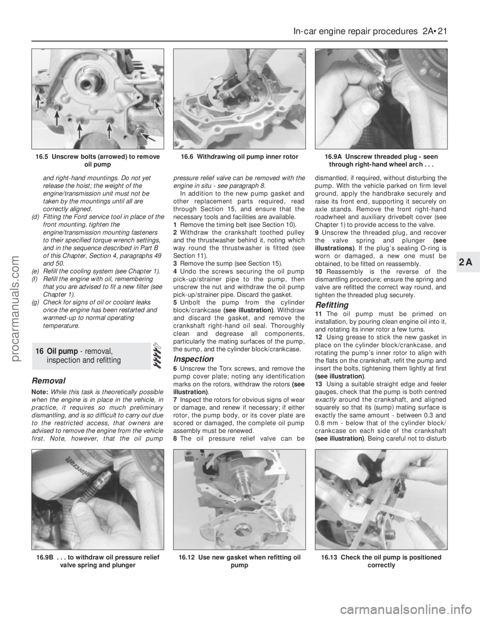
block/crankcase (see illustration). Withdraw
and discard the gasket, and remove the
crankshaft right-hand oil seal. Thoroughly
clean and degrease all components,
particularly the mating surfaces of the pump,
the sump, and the cylinder block/crankcase.
Inspection
6Unscrew the Torx screws, and remove the
pump cover plate; noting any identification
marks on the rotors, withdraw the rotors (see
illustration).
7Inspect the rotors for obvious signs of wear
or damage, and renew if necessary; if either
rotor, the pump body, or its cover plate are
scored or damaged, the complete oil pump
assembly must be renewed.
8The oil pressure relief valve can bedismantled, if required, without disturbing the
pump. With the vehicle parked on firm level
ground, apply the handbrake securely and
raise its front end, supporting it securely on
axle stands. Remove the front right-hand
roadwheel and auxiliary drivebelt cover (see
Chapter 1) to provide access to the valve.
9Unscrew the threaded plug, and recover
the valve spring and plunger (see
illustrations). If the plug’s sealing O-ring is
worn or damaged, a new one must be
obtained, to be fitted on reassembly.
10Reassembly is the reverse of the
dismantling procedure; ensure the spring and
valve are refitted the correct way round, and
tighten the threaded plug securely.
Refitting
11The oil pump must be primed on
installation, by pouring clean engine oil into it,
and rotating its inner rotor a few turns.
12Using grease to stick the new gasket in
place on the cylinder block/crankcase, and
rotating the pump’s inner rotor to align with
the flats on the crankshaft, refit the pump and
insert the bolts, tightening them lightly at first
(see illustration).
13Using a suitable straight edge and feeler
gauges, check that the pump is both centred
exactlyaround the crankshaft, and aligned
squarely so that its (sump) mating surface is
exactly the same amount - between 0.3 and
0.8 mm - below that of the cylinder block/
crankcase on each side of the crankshaft
(see illustration). Being careful not to disturb
16 Oil pump - removal,
inspection and refitting
In-car engine repair procedures 2A•21
2A
16.9B . . . to withdraw oil pressure relief
valve spring and plunger16.12 Use new gasket when refitting oil
pump16.13 Check the oil pump is positioned
correctly
16.5 Unscrew bolts (arrowed) to remove
oil pump16.6 Withdrawing oil pump inner rotor16.9A Unscrew threaded plug - seen
through right-hand wheel arch . . .
procarmanuals.com
Page 63 of 279
3Clean the seal housing and crankshaft,
polishing off any burrs or raised edges, which
may have caused the seal to fail in the first
place.
4Refit the oil pump (see Section 16). Grease
the lips and periphery of the new seal, to ease
installation.
5To fit a new seal, Ford recommend the use
of their service tool 21-093A, with the
crankshaft pulley bolt, to draw the seal into
place; an alternative can be arranged using a
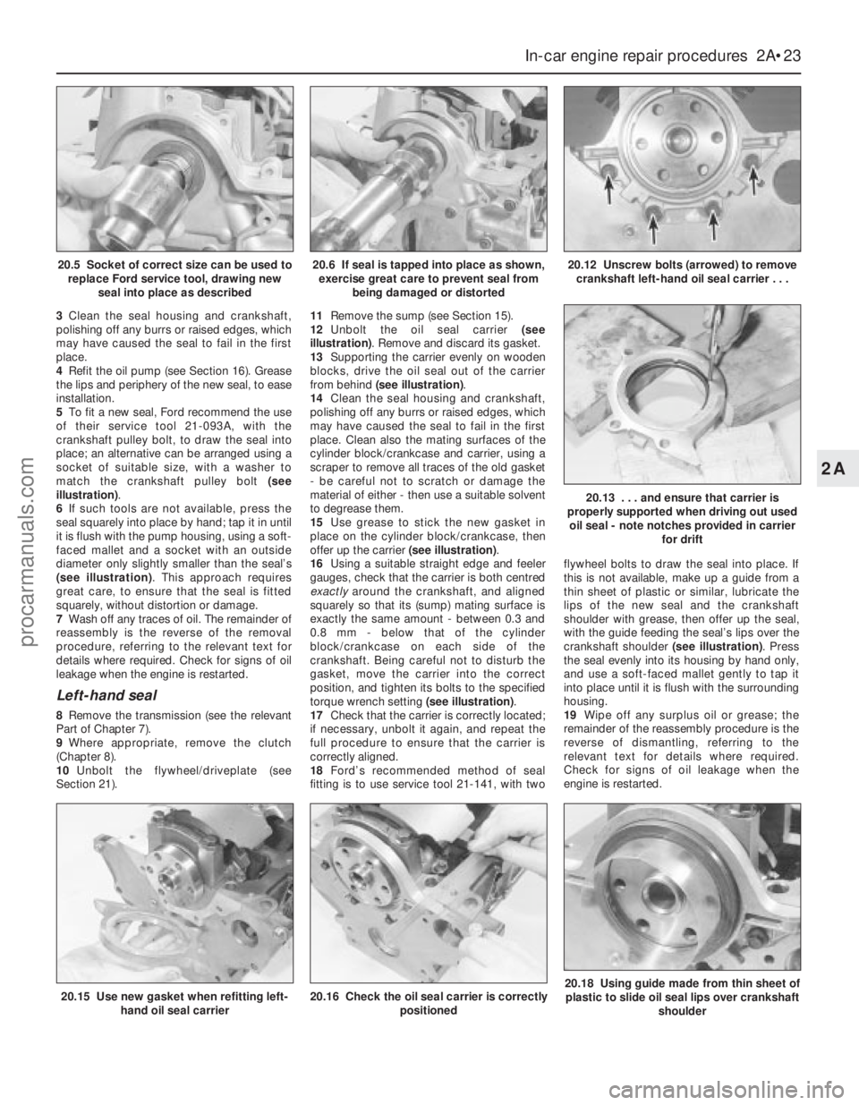
socket of suitable size, with a washer to
match the crankshaft pulley bolt (see
illustration).
6If such tools are not available, press the
seal squarely into place by hand; tap it in until
it is flush with the pump housing, using a soft-
faced mallet and a socket with an outside
diameter only slightly smaller than the seal’s
(see illustration). This approach requires
great care, to ensure that the seal is fitted
squarely, without distortion or damage.
7Wash off any traces of oil. The remainder of
reassembly is the reverse of the removal
procedure, referring to the relevant text for
details where required. Check for signs of oil
leakage when the engine is restarted.
Left-hand seal
8Remove the transmission (see the relevant
Part of Chapter 7).
9Where appropriate, remove the clutch
(Chapter 8).
10Unbolt the flywheel/driveplate (see
Section 21).11Remove the sump (see Section 15).
12Unbolt the oil seal carrier (see
illustration). Remove and discard its gasket.
13Supporting the carrier evenly on wooden
blocks, drive the oil seal out of the carrier
from behind (see illustration).
14Clean the seal housing and crankshaft,
polishing off any burrs or raised edges, which
may have caused the seal to fail in the first
place. Clean also the mating surfaces of the
cylinder block/crankcase and carrier, using a
scraper to remove all traces of the old gasket
- be careful not to scratch or damage the
material of either - then use a suitable solvent
to degrease them.
15Use grease to stick the new gasket in
place on the cylinder block/crankcase, then
offer up the carrier (see illustration).
16Using a suitable straight edge and feeler
gauges, check that the carrier is both centred
exactlyaround the crankshaft, and aligned
squarely so that its (sump) mating surface is
exactly the same amount - between 0.3 and
0.8 mm - below that of the cylinder
block/crankcase on each side of the
crankshaft. Being careful not to disturb the
gasket, move the carrier into the correct
position, and tighten its bolts to the specified
torque wrench setting (see illustration).
17Check that the carrier is correctly located;
if necessary, unbolt it again, and repeat the
full procedure to ensure that the carrier is
correctly aligned.
18Ford’s recommended method of seal
fitting is to use service tool 21-141, with twoflywheel bolts to draw the seal into place. If
this is not available, make up a guide from a
thin sheet of plastic or similar, lubricate the
lips of the new seal and the crankshaft
shoulder with grease, then offer up the seal,
with the guide feeding the seal’s lips over the
crankshaft shoulder (see illustration). Press
the seal evenly into its housing by hand only,
and use a soft-faced mallet gently to tap it
into place until it is flush with the surrounding
housing.
19Wipe off any surplus oil or grease; the
remainder of the reassembly procedure is the
reverse of dismantling, referring to the
relevant text for details where required.
Check for signs of oil leakage when the
engine is restarted.
In-car engine repair procedures 2A•23
2A
20.15 Use new gasket when refitting left-
hand oil seal carrier20.16 Check the oil seal carrier is correctly
positioned20.18 Using guide made from thin sheet of
plastic to slide oil seal lips over crankshaft
shoulder
20.5 Socket of correct size can be used to
replace Ford service tool, drawing new
seal into place as described20.6 If seal is tapped into place as shown,
exercise great care to prevent seal from
being damaged or distorted20.12 Unscrew bolts (arrowed) to remove
crankshaft left-hand oil seal carrier . . .
20.13 . . . and ensure that carrier is
properly supported when driving out used
oil seal - note notches provided in carrier
for drift
procarmanuals.com
Page 64 of 279
Removal
1Remove the transmission (see the relevant
Part of Chapter 7). Now is a good time to
check components such as oil seals and
renew them if necessary.
2Where appropriate, remove the clutch
(Chapter 8). Now is a good time to check or
renew the clutch components and pilot
bearing.
3Use a centre-punch or paint to make
alignment marks on the flywheel/driveplate
and crankshaft, to ensure correct alignment
during refitting.
4Prevent the flywheel/driveplate from
turning by locking the ring gear teeth, or by
bolting a strap between the flywheel/
driveplate and the cylinder block/
crankcase. Slacken the bolts evenly until all
are free.
5Remove each bolt in turn, and ensure that
new replacements are obtained for
reassembly; these bolts are subjected to
severe stresses, and so must be renewed,
regardless of their apparent condition,
whenever they are disturbed.
6Noting the reinforcing plate (automatic
transmission-equipped models only),
withdraw the flywheel/driveplate; do not drop
it - it is very heavy.
Inspection
7Clean the flywheel/driveplate to remove
grease and oil. Inspect the surface for cracks,
rivet grooves, burned areas and score marks.
Light scoring can be removed with emery
cloth. Check for cracked and broken ring gear
teeth. Lay the flywheel/driveplate on a flat
surface, and use a straight edge to check for
warpage.
8Clean and inspect the mating surfaces of
the flywheel/driveplate and the crankshaft. If
the crankshaft left-hand seal is leaking, renew
it (see Section 20) before refitting the
flywheel/driveplate.
9While the flywheel/driveplate is removed,clean carefully its inboard (right-hand) face,
particularly the recesses which serve as the
reference points for the crankshaft
speed/position sensor. Clean the sensor’s tip,
and check that the sensor is securely
fastened.
Refitting
10On refitting, ensure that the
engine/transmission adaptor plate is in place
(where necessary), then fit the
flywheel/driveplate to the crankshaft so that
all bolt holes align - it will fit only one way -
check this using the marks made on removal.
Do not forget the reinforcing plate (where
fitted).
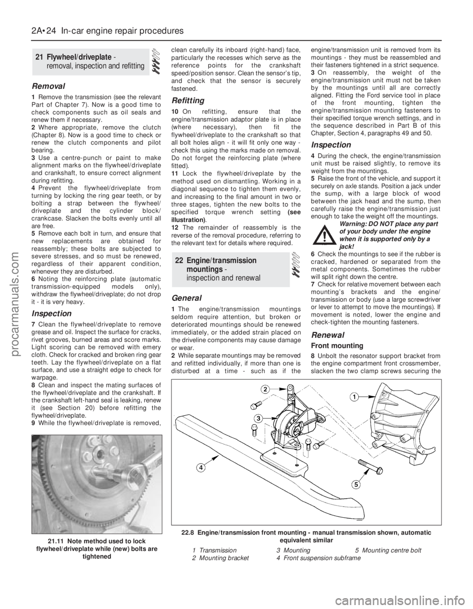
11Lock the flywheel/driveplate by the
method used on dismantling. Working in a
diagonal sequence to tighten them evenly,
and increasing to the final amount in two or
three stages, tighten the new bolts to the
specified torque wrench setting (see
illustration).
12The remainder of reassembly is the
reverse of the removal procedure, referring to
the relevant text for details where required.
General
1The engine/transmission mountings
seldom require attention, but broken or
deteriorated mountings should be renewed
immediately, or the added strain placed on
the driveline components may cause damage
or wear.
2While separate mountings may be removed
and refitted individually, if more than one is
disturbed at a time - such as if theengine/transmission unit is removed from its
mountings - they must be reassembled and
their fasteners tightened in a strict sequence.
3On reassembly, the weight of the
engine/transmission unit must not be taken
by the mountings until all are correctly
aligned. Fitting the Ford service tool in place
of the front mounting, tighten the
engine/transmission mounting fasteners to
their specified torque wrench settings, and in
the sequence described in Part B of this
Chapter, Section 4, paragraphs 49 and 50.
Inspection
4During the check, the engine/transmission
unit must be raised slightly, to remove its
weight from the mountings.
5Raise the front of the vehicle, and support it
securely on axle stands. Position a jack under
the sump, with a large block of wood
between the jack head and the sump, then
carefully raise the engine/transmission just
enough to take the weight off the mountings.
Warning: DO NOT place any part
of your body under the engine
when it is supported only by a
jack!
6Check the mountings to see if the rubber is
cracked, hardened or separated from the
metal components. Sometimes the rubber
will split right down the centre.
7Check for relative movement between each
mounting’s brackets and the engine/
transmission or body (use a large screwdriver
or lever to attempt to move the mountings). If
movement is noted, lower the engine and
check-tighten the mounting fasteners.
Renewal
Front mounting
8Unbolt the resonator support bracket from
the engine compartment front crossmember,
slacken the two clamp screws securing the
22 Engine/transmission
mountings -
inspection and renewal
21 Flywheel/driveplate -
removal, inspection and refitting
2A•24 In-car engine repair procedures
21.11 Note method used to lock
flywheel/driveplate while (new) bolts are
tightened
22.8 Engine/transmission front mounting - manual transmission shown, automatic
equivalent similar
1 Transmission 3 Mounting 5 Mounting centre bolt
2 Mounting bracket 4 Front suspension subframe
procarmanuals.com