1993 FORD MONDEO wheel bolt torque
[x] Cancel search: wheel bolt torquePage 156 of 279
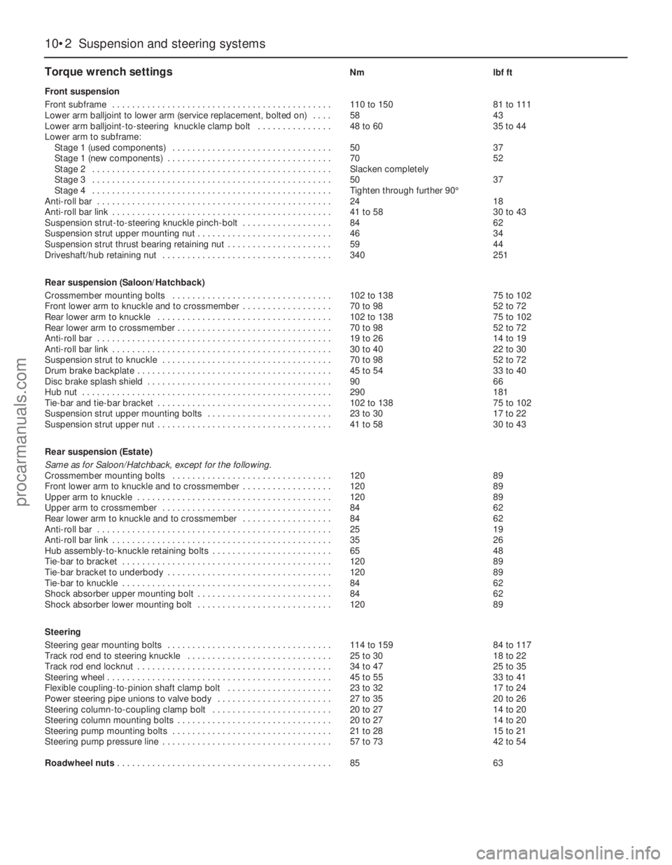
Torque wrench settingsNm lbf ft
Front suspension
Front subframe . . . . . . . . . . . . . . . . . . . . . . . . . . . . . . . . . . . . . . . . . . . . 110 to 150 81 to 111
Lower arm balljoint to lower arm (service replacement, bolted on) . . . . 58 43
Lower arm balljoint-to-steering knuckle clamp bolt . . . . . . . . . . . . . . . 48 to 60 35 to 44
Lower arm to subframe:
Stage 1 (used components) . . . . . . . . . . . . . . . . . . . . . . . . . . . . . . . . 50 37
Stage 1 (new components) . . . . . . . . . . . . . . . . . . . . . . . . . . . . . . . . . 70 52
Stage 2 . . . . . . . . . . . . . . . . . . . . . . . . . . . . . . . . . . . . . . . . . . . . . . . . Slacken completely
Stage 3 . . . . . . . . . . . . . . . . . . . . . . . . . . . . . . . . . . . . . . . . . . . . . . . . 50 37
Stage 4 . . . . . . . . . . . . . . . . . . . . . . . . . . . . . . . . . . . . . . . . . . . . . . . . Tighten through further 90°
Anti-roll bar . . . . . . . . . . . . . . . . . . . . . . . . . . . . . . . . . . . . . . . . . . . . . . . 24 18
Anti-roll bar link . . . . . . . . . . . . . . . . . . . . . . . . . . . . . . . . . . . . . . . . . . . . 41 to 58 30 to 43
Suspension strut-to-steering knuckle pinch-bolt . . . . . . . . . . . . . . . . . . 84 62
Suspension strut upper mounting nut . . . . . . . . . . . . . . . . . . . . . . . . . . . 46 34
Suspension strut thrust bearing retaining nut . . . . . . . . . . . . . . . . . . . . . 59 44
Driveshaft/hub retaining nut . . . . . . . . . . . . . . . . . . . . . . . . . . . . . . . . . . 340 251
Rear suspension (Saloon/Hatchback)
Crossmember mounting bolts . . . . . . . . . . . . . . . . . . . . . . . . . . . . . . . . 102 to 138 75 to 102
Front lower arm to knuckle and to crossmember . . . . . . . . . . . . . . . . . . 70 to 98 52 to 72
Rear lower arm to knuckle . . . . . . . . . . . . . . . . . . . . . . . . . . . . . . . . . . . 102 to 138 75 to 102
Rear lower arm to crossmember . . . . . . . . . . . . . . . . . . . . . . . . . . . . . . . 70 to 98 52 to 72
Anti-roll bar . . . . . . . . . . . . . . . . . . . . . . . . . . . . . . . . . . . . . . . . . . . . . . . 19 to 26 14 to 19
Anti-roll bar link . . . . . . . . . . . . . . . . . . . . . . . . . . . . . . . . . . . . . . . . . . . . 30 to 40 22 to 30
Suspension strut to knuckle . . . . . . . . . . . . . . . . . . . . . . . . . . . . . . . . . . 70 to 98 52 to 72
Drum brake backplate . . . . . . . . . . . . . . . . . . . . . . . . . . . . . . . . . . . . . . . 45 to 54 33 to 40
Disc brake splash shield . . . . . . . . . . . . . . . . . . . . . . . . . . . . . . . . . . . . . 90 66
Hub nut . . . . . . . . . . . . . . . . . . . . . . . . . . . . . . . . . . . . . . . . . . . . . . . . . . 290 181
Tie-bar and tie-bar bracket . . . . . . . . . . . . . . . . . . . . . . . . . . . . . . . . . . . 102 to 138 75 to 102
Suspension strut upper mounting bolts . . . . . . . . . . . . . . . . . . . . . . . . . 23 to 30 17 to 22
Suspension strut upper nut . . . . . . . . . . . . . . . . . . . . . . . . . . . . . . . . . . . 41 to 58 30 to 43
Rear suspension (Estate)
Same as for Saloon/Hatchback, except for the following.
Crossmember mounting bolts . . . . . . . . . . . . . . . . . . . . . . . . . . . . . . . . 120 89
Front lower arm to knuckle and to crossmember . . . . . . . . . . . . . . . . . . 120 89
Upper arm to knuckle . . . . . . . . . . . . . . . . . . . . . . . . . . . . . . . . . . . . . . . 120 89
Upper arm to crossmember . . . . . . . . . . . . . . . . . . . . . . . . . . . . . . . . . . 84 62
Rear lower arm to knuckle and to crossmember . . . . . . . . . . . . . . . . . . 84 62
Anti-roll bar . . . . . . . . . . . . . . . . . . . . . . . . . . . . . . . . . . . . . . . . . . . . . . . 25 19
Anti-roll bar link . . . . . . . . . . . . . . . . . . . . . . . . . . . . . . . . . . . . . . . . . . . . 35 26
Hub assembly-to-knuckle retaining bolts . . . . . . . . . . . . . . . . . . . . . . . . 65 48
Tie-bar to bracket . . . . . . . . . . . . . . . . . . . . . . . . . . . . . . . . . . . . . . . . . . 120 89
Tie-bar bracket to underbody . . . . . . . . . . . . . . . . . . . . . . . . . . . . . . . . . 120 89
Tie-bar to knuckle . . . . . . . . . . . . . . . . . . . . . . . . . . . . . . . . . . . . . . . . . . 84 62
Shock absorber upper mounting bolt . . . . . . . . . . . . . . . . . . . . . . . . . . . 84 62
Shock absorber lower mounting bolt . . . . . . . . . . . . . . . . . . . . . . . . . . . 120 89
Steering
Steering gear mounting bolts . . . . . . . . . . . . . . . . . . . . . . . . . . . . . . . . . 114 to 159 84 to 117
Track rod end to steering knuckle . . . . . . . . . . . . . . . . . . . . . . . . . . . . . 25 to 30 18 to 22
Track rod end locknut . . . . . . . . . . . . . . . . . . . . . . . . . . . . . . . . . . . . . . . 34 to 47 25 to 35
Steering wheel . . . . . . . . . . . . . . . . . . . . . . . . . . . . . . . . . . . . . . . . . . . . . 45 to 55 33 to 41
Flexible coupling-to-pinion shaft clamp bolt . . . . . . . . . . . . . . . . . . . . . 23 to 32 17 to 24
Power steering pipe unions to valve body . . . . . . . . . . . . . . . . . . . . . . . 27 to 35 20 to 26
Steering column-to-coupling clamp bolt . . . . . . . . . . . . . . . . . . . . . . . . 20 to 27 14 to 20
Steering column mounting bolts . . . . . . . . . . . . . . . . . . . . . . . . . . . . . . . 20 to 27 14 to 20
Steering pump mounting bolts . . . . . . . . . . . . . . . . . . . . . . . . . . . . . . . . 21 to 28 15 to 21
Steering pump pressure line . . . . . . . . . . . . . . . . . . . . . . . . . . . . . . . . . . 57 to 73 42 to 54
Roadwheel nuts . . . . . . . . . . . . . . . . . . . . . . . . . . . . . . . . . . . . . . . . . . . 85 63
10•2 Suspension and steering systems
procarmanuals.com
Page 159 of 279
Since most of the procedures dealt with in
this Chapter involve jacking up the vehicle
and working underneath it, a good pair of axle
stands will be needed. A hydraulic trolley jack
is the preferred type of jack to lift the vehicle,
and it can also be used to support certain
components during removal and refitting
operations.
Warning: Never, under any
circumstances, rely on a jack to
support the vehicle while working
beneath it. When jacking up the vehicle, do
not lift or support it beneath the front or
rear subframes.
Removal
1Apply the handbrake. Remove the wheel
cover from the relevant front wheel, and
loosen (but do not remove) the driveshaft/hub
nut. This nut is very tight.
2Loosen the front wheel nuts, jack up the
front of the vehicle and support it on axle
stands. Remove the front wheel.
3Extract the split pin from the track rod end
balljoint nut. Unscrew the nut, and detach the
rod from the arm on the steering knuckle
using a conventional balljoint removal tool.
Take care not to damage the balljoint seal.
4Remove the ABS sensor (when fitted) as
described in Chapter 9.
5Remove the brake caliper and brake disc as
described in Chapter 9, but do not disconnect
the flexible hose from the caliper. Suspend
the caliper from a suitable point under the
wheel arch, taking care not to strain the hose.
6Unscrew and remove the driveshaft/hub
nut. Note that the nut is of special laminated
design, and should only be re-used a
maximum of 5 times. (It is a good idea to file a
small notch on the nut every time it is
removed.) Obtain a new nut if necessary.
7Note which way round the lower arm
balljoint clamp bolt is fitted, then unscrew and
remove it from the knuckle assembly. Lever
the balljoint down from the knuckle; if it is
tight, prise the clamp open using a large flat-
bladed tool. Take care not to damage the
balljoint seal during the separation procedure.
8Unscrew and remove the pinch-bolt
securing the steering knuckle assembly to the
front suspension strut, noting which way
round it is fitted. Prise open the clamp using a
wedge-shaped tool, and release the knuckle
from the strut. If necessary, tap the knuckle
downwards with a soft-headed mallet to
separate the two components. Support the
knuckle on an axle stand.
9Pull the steering knuckle and hub assembly
from the driveshaft splines. If it is tight,
connect a universal puller to the hub flange,
and withdraw it from the driveshaft. When the
driveshaft is free, support it on an axle stand,
or suspend it from a suitable point under thewheel arch, making sure that the inner
constant velocity joint is not turned through
more than 18°. (Damage may occur if the joint
is turned through too great an angle.)
Refitting
10Lift the steering knuckle and hub
assembly onto the driveshaft splines, and
support the assembly on an axle stand.
11Locate the assembly on the front
suspension strut. Insert the pinch-bolt with its
head facing forwards. Fit the nut and tighten it
to the specified torque.
12Refit the lower arm balljoint to the knuckle
assembly, and insert the clamp bolt with its
head facing forwards. Refit the nut and tighten
it to the specified torque.
13Refit the driveshaft/hub nut, and tighten it
moderately at this stage. Final tightening of
the nut is made with the vehicle lowered to the
ground.
14Refit the brake caliper and brake disc as
described in Chapter 9.
15Where fitted, refit the ABS sensor as
described in Chapter 9.
16Reconnect the track rod end balljoint to
the steering arm, and tighten the nut to the
specified torque. Check that the split pin
holes are aligned; if necessary, turn the nut to
the nearest alignment, making sure that the
torque wrench setting is still within the
specified range. Insert a new split pin, and
bend it back to secure.
17Refit the front wheel, and lower the
vehicle to the ground. Tighten the wheel nuts
to the specified torque.
18Tighten the driveshaft/hub nut to the
specified torque, and refit the wheel cover.
Inspection
1The front hub bearings are non-adjustable,
and are supplied already greased.
2To check the bearings for excessive wear,
apply the handbrake, jack up the front of the
vehicle and support it on axle stands.
3Grip the front wheel at top and bottom, and
attempt to rock it. If excessive movement is
noted, it may be that the hub bearings are
worn. Do not confuse wear in the driveshaft
outer joint or front suspension lower arm
balljoint with wear in the bearings. Hub
bearing wear will show up as roughness or
vibration when the wheel is spun; it will also
be noticeable as a rumbling or growling noise
when driving.
Renewal
4Remove the steering knuckle and hub
assembly as described in Section 2.
5The hub must now be removed from the
bearing inner races. It is preferable to use a
press to do this, but it is possible to drive outthe hub using a length of metal tube of
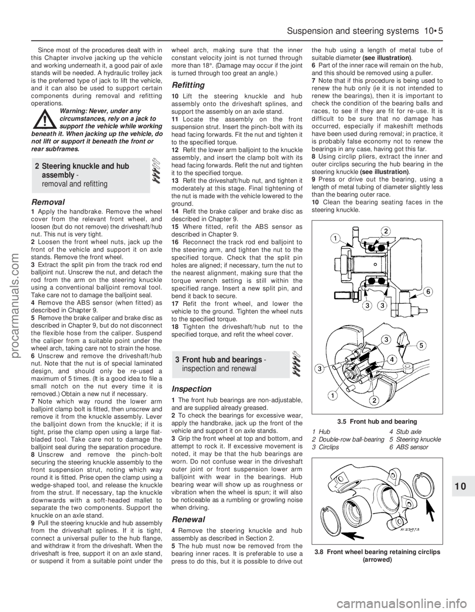
suitable diameter (see illustration).
6Part of the inner race will remain on the hub,
and this should be removed using a puller.
7Note that if this procedure is being used to
renew the hub only (ie it is not intended to
renew the bearings), then it is important to
check the condition of the bearing balls and
races, to see if they are fit for re-use. It is
difficult to be sure that no damage has
occurred, especially if makeshift methods
have been used during removal; in practice, it
is probably false economy not to renew the
bearings in any case, having got this far.
8Using circlip pliers, extract the inner and
outer circlips securing the hub bearing in the
steering knuckle (see illustration).
9Press or drive out the bearing, using a
length of metal tubing of diameter slightly less
than the bearing outer race.
10Clean the bearing seating faces in the
steering knuckle.
3 Front hub and bearings -
inspection and renewal
2 Steering knuckle and hub
assembly -
removal and refitting
Suspension and steering systems 10•5
10
3.5 Front hub and bearing
1 Hub 4 Stub axle
2 Double-row ball-bearing 5 Steering knuckle
3 Circlips 6 ABS sensor
3.8 Front wheel bearing retaining circlips
(arrowed)
procarmanuals.com
Page 160 of 279
11Locate one of the circlips in the outer
groove of the knuckle.
12Press or drive the new bearing into the
knuckle until it contacts the circlip, using a
length of metal tube of diameter slightly less
than the outer race. Do not apply any
pressure to the inner race.
13Locate the remaining circlip in the inner
groove of the knuckle.
14Support the inner race on a length of
metal tube, then press or drive the hub fully
into the bearing.
15Refit the steering knuckle and hub
assembly as described in Section 2.
Removal
1Apply the handbrake, then jack up the front
of the vehicle and support it on axle stands.
Remove the appropriate front wheel.
2Unbolt the brake hose support bracket from
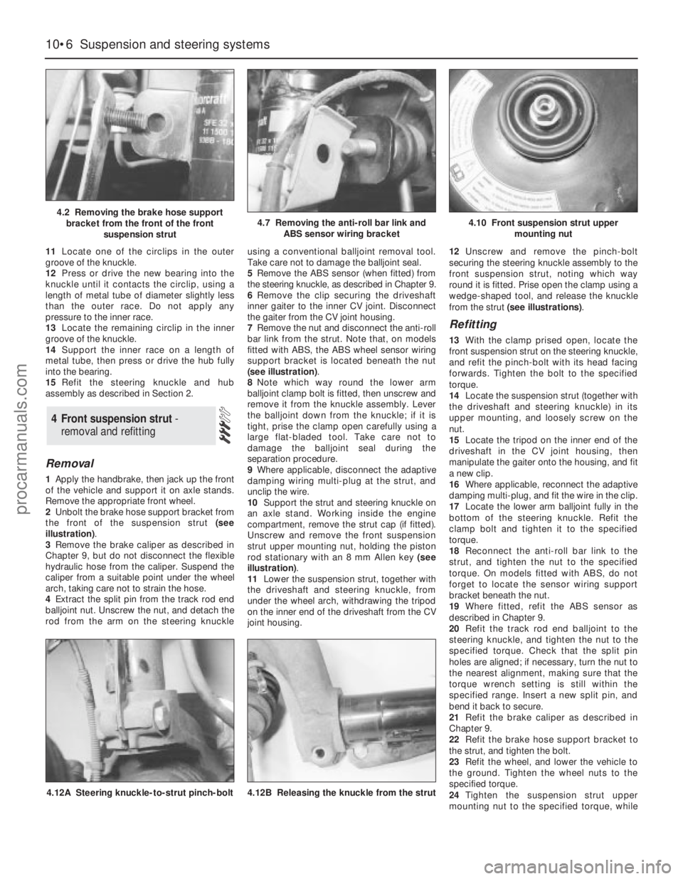
the front of the suspension strut (see
illustration).
3Remove the brake caliper as described in
Chapter 9, but do not disconnect the flexible
hydraulic hose from the caliper. Suspend the
caliper from a suitable point under the wheel
arch, taking care not to strain the hose.
4Extract the split pin from the track rod end
balljoint nut. Unscrew the nut, and detach the
rod from the arm on the steering knuckleusing a conventional balljoint removal tool.
Take care not to damage the balljoint seal.
5Remove the ABS sensor (when fitted) from
the steering knuckle, as described in Chapter 9.
6Remove the clip securing the driveshaft
inner gaiter to the inner CV joint. Disconnect
the gaiter from the CV joint housing.
7Remove the nut and disconnect the anti-roll
bar link from the strut. Note that, on models
fitted with ABS, the ABS wheel sensor wiring
support bracket is located beneath the nut
(see illustration).
8Note which way round the lower arm
balljoint clamp bolt is fitted, then unscrew and
remove it from the knuckle assembly. Lever
the balljoint down from the knuckle; if it is
tight, prise the clamp open carefully using a
large flat-bladed tool. Take care not to
damage the balljoint seal during the
separation procedure.
9Where applicable, disconnect the adaptive
damping wiring multi-plug at the strut, and
unclip the wire.
10Support the strut and steering knuckle on
an axle stand. Working inside the engine
compartment, remove the strut cap (if fitted).
Unscrew and remove the front suspension
strut upper mounting nut, holding the piston
rod stationary with an 8 mm Allen key (see
illustration).
11Lower the suspension strut, together with
the driveshaft and steering knuckle, from
under the wheel arch, withdrawing the tripod
on the inner end of the driveshaft from the CV
joint housing.12Unscrew and remove the pinch-bolt
securing the steering knuckle assembly to the
front suspension strut, noting which way
round it is fitted. Prise open the clamp using a
wedge-shaped tool, and release the knuckle
from the strut (see illustrations).
Refitting
13With the clamp prised open, locate the
front suspension strut on the steering knuckle,
and refit the pinch-bolt with its head facing
forwards. Tighten the bolt to the specified
torque.
14Locate the suspension strut (together with
the driveshaft and steering knuckle) in its
upper mounting, and loosely screw on the
nut.
15Locate the tripod on the inner end of the
driveshaft in the CV joint housing, then
manipulate the gaiter onto the housing, and fit
a new clip.
16Where applicable, reconnect the adaptive
damping multi-plug, and fit the wire in the clip.
17Locate the lower arm balljoint fully in the
bottom of the steering knuckle. Refit the
clamp bolt and tighten it to the specified
torque.
18Reconnect the anti-roll bar link to the
strut, and tighten the nut to the specified
torque. On models fitted with ABS, do not
forget to locate the sensor wiring support
bracket beneath the nut.
19Where fitted, refit the ABS sensor as
described in Chapter 9.
20Refit the track rod end balljoint to the
steering knuckle, and tighten the nut to the
specified torque. Check that the split pin
holes are aligned; if necessary, turn the nut to
the nearest alignment, making sure that the
torque wrench setting is still within the
specified range. Insert a new split pin, and
bend it back to secure.
21Refit the brake caliper as described in
Chapter 9.
22Refit the brake hose support bracket to
the strut, and tighten the bolt.
23Refit the wheel, and lower the vehicle to
the ground. Tighten the wheel nuts to the
specified torque.
24Tighten the suspension strut upper
mounting nut to the specified torque, while
4 Front suspension strut -
removal and refitting
10•6 Suspension and steering systems
4.2 Removing the brake hose support
bracket from the front of the front
suspension strut4.7 Removing the anti-roll bar link and
ABS sensor wiring bracket4.10 Front suspension strut upper
mounting nut
4.12A Steering knuckle-to-strut pinch-bolt4.12B Releasing the knuckle from the strut
procarmanuals.com
Page 162 of 279
spring must now be carefully released from
the compressor. If it is to be re-used, the
spring can be left in compression.
7With the strut assembly now completely
dismantled, examine all the components for
wear and damage, and check the bearing for
smoothness of operation. Renew components
as necessary.
8Examine the strut for signs of fluid leakage.
Check the strut piston for signs of pitting
along its entire length, and check the strut
body for signs of damage. Test the operation
of the strut, while holding it in an upright
position, by moving the piston through a full
stroke, and then through short strokes of 50
to 100 mm. In both cases, the resistance felt
should be smooth and continuous. If the
resistance is jerky, uneven, or if there is any
visible sign of wear or damage to the strut,
renewal is necessary.
9Reassembly is a reversal of dismantling,
noting the following points:
(a) Make sure that the coil spring ends are
correctly located in the upper and lower
seats before releasing the compressor.
(b) Check that the bearing is correctly fitted
to the piston rod seat.
(c) Tighten the thrust bearing retaining nut to
the specified torque.
Removal
1Apply the handbrake, jack up the front of
the vehicle and support it on axle stands.
Remove both front wheels.
2Unscrew the nuts, and disconnect the anti-
roll bar links from the front suspension struts
on both sides of the vehicle. Note that, on
models with ABS, the wheel sensor wiring
support brackets are located beneath the nuts
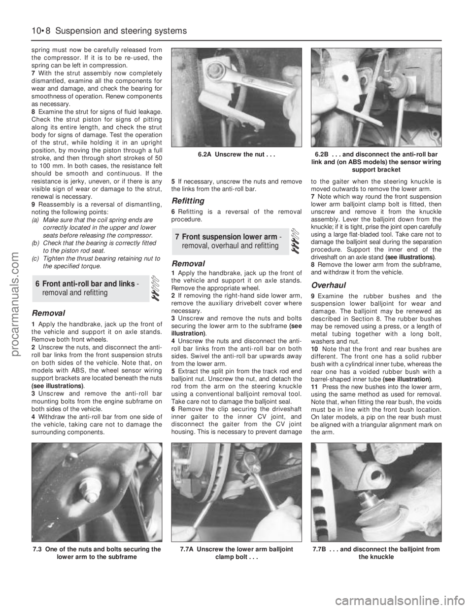
(see illustrations).
3Unscrew and remove the anti-roll bar
mounting bolts from the engine subframe on
both sides of the vehicle.
4Withdraw the anti-roll bar from one side of
the vehicle, taking care not to damage the
surrounding components.5If necessary, unscrew the nuts and remove
the links from the anti-roll bar.
Refitting
6Refitting is a reversal of the removal
procedure.
Removal
1Apply the handbrake, jack up the front of
the vehicle and support it on axle stands.
Remove the appropriate wheel.
2If removing the right-hand side lower arm,
remove the auxiliary drivebelt cover where
necessary.
3Unscrew and remove the nuts and bolts
securing the lower arm to the subframe (see
illustration).
4Unscrew the nuts and disconnect the anti-
roll bar links from the anti-roll bar on both
sides. Swivel the anti-roll bar upwards away
from the lower arm.
5Extract the split pin from the track rod end
balljoint nut. Unscrew the nut, and detach the
rod from the arm on the steering knuckle
using a conventional balljoint removal tool.
Take care not to damage the balljoint seal.
6Remove the clip securing the driveshaft
inner gaiter to the inner CV joint, and
disconnect the gaiter from the CV joint
housing. This is necessary to prevent damageto the gaiter when the steering knuckle is
moved outwards to remove the lower arm.
7Note which way round the front suspension
lower arm balljoint clamp bolt is fitted, then
unscrew and remove it from the knuckle
assembly. Lever the balljoint down from the
knuckle; if it is tight, prise the joint open carefully
using a large flat-bladed tool. Take care not to
damage the balljoint seal during the separation
procedure. Support the inner end of the
driveshaft on an axle stand (see illustrations).
8Remove the lower arm from the subframe,
and withdraw it from the vehicle.
Overhaul
9Examine the rubber bushes and the
suspension lower balljoint for wear and
damage. The balljoint may be renewed as
described in Section 8. The rubber bushes
may be removed using a press, or a length of
metal tubing together with a long bolt,
washers and nut.
10Note that the front and rear bushes are
different. The front one has a solid rubber
bush with a cylindrical inner tube, whereas the
rear one has a voided rubber bush with a
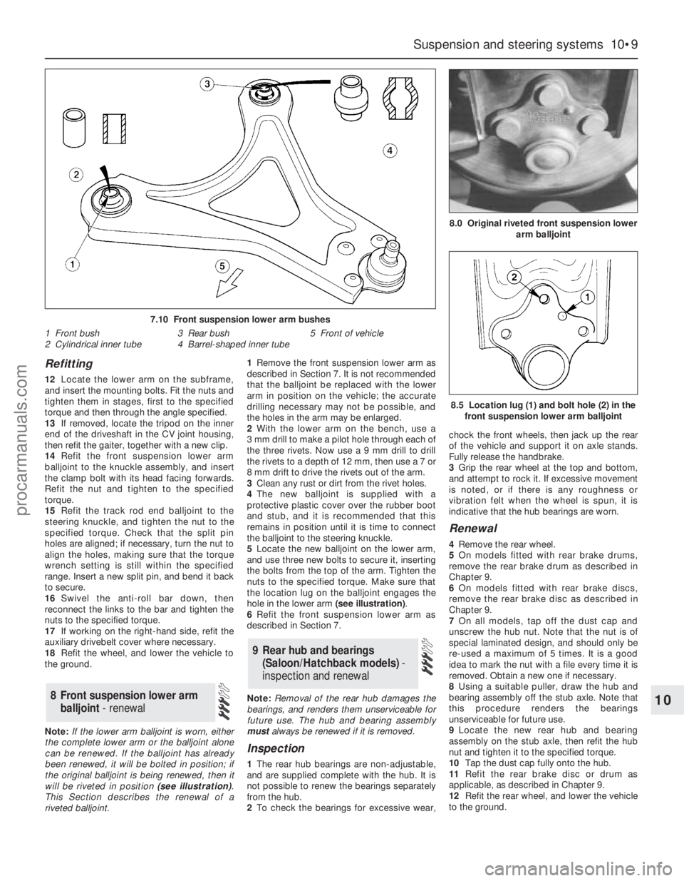
barrel-shaped inner tube (see illustration).
11Press the new bushes into the lower arm,
using the same method as used for removal.
Note that, when fitting the rear bush, the voids
must be in line with the front bush location.
On later models, a pip on the rear bush must
be aligned with a triangular alignment mark on
the arm.
7 Front suspension lower arm -
removal, overhaul and refitting
6 Front anti-roll bar and links -
removal and refitting
10•8 Suspension and steering systems
6.2A Unscrew the nut . . .6.2B . . . and disconnect the anti-roll bar
link and (on ABS models) the sensor wiring
support bracket
7.3 One of the nuts and bolts securing the
lower arm to the subframe7.7A Unscrew the lower arm balljoint
clamp bolt . . .7.7B . . . and disconnect the balljoint from
the knuckle
procarmanuals.com
Page 163 of 279
Refitting
12Locate the lower arm on the subframe,
and insert the mounting bolts. Fit the nuts and
tighten them in stages, first to the specified
torque and then through the angle specified.
13If removed, locate the tripod on the inner
end of the driveshaft in the CV joint housing,
then refit the gaiter, together with a new clip.
14Refit the front suspension lower arm
balljoint to the knuckle assembly, and insert
the clamp bolt with its head facing forwards.
Refit the nut and tighten to the specified
torque.
15Refit the track rod end balljoint to the
steering knuckle, and tighten the nut to the
specified torque. Check that the split pin
holes are aligned; if necessary, turn the nut to
align the holes, making sure that the torque
wrench setting is still within the specified
range. Insert a new split pin, and bend it back
to secure.
16Swivel the anti-roll bar down, then
reconnect the links to the bar and tighten the
nuts to the specified torque.
17If working on the right-hand side, refit the
auxiliary drivebelt cover where necessary.
18Refit the wheel, and lower the vehicle to
the ground.
Note:If the lower arm balljoint is worn, either
the complete lower arm or the balljoint alone
can be renewed. If the balljoint has already
been renewed, it will be bolted in position; if
the original balljoint is being renewed, then it
will be riveted in position (see illustration).
This Section describes the renewal of a
riveted balljoint.1Remove the front suspension lower arm as
described in Section 7. It is not recommended
that the balljoint be replaced with the lower
arm in position on the vehicle; the accurate
drilling necessary may not be possible, and
the holes in the arm may be enlarged.
2With the lower arm on the bench, use a
3 mm drill to make a pilot hole through each of
the three rivets. Now use a 9 mm drill to drill
the rivets to a depth of 12 mm, then use a 7 or
8 mm drift to drive the rivets out of the arm.
3Clean any rust or dirt from the rivet holes.
4The new balljoint is supplied with a
protective plastic cover over the rubber boot
and stub, and it is recommended that this
remains in position until it is time to connect
the balljoint to the steering knuckle.
5Locate the new balljoint on the lower arm,
and use three new bolts to secure it, inserting
the bolts from the top of the arm. Tighten the
nuts to the specified torque. Make sure that
the location lug on the balljoint engages the
hole in the lower arm (see illustration).
6Refit the front suspension lower arm as
described in Section 7.
Note:Removal of the rear hub damages the
bearings, and renders them unserviceable for
future use. The hub and bearing assembly
mustalways be renewed if it is removed.
Inspection
1The rear hub bearings are non-adjustable,
and are supplied complete with the hub. It is
not possible to renew the bearings separately
from the hub.
2To check the bearings for excessive wear,chock the front wheels, then jack up the rear
of the vehicle and support it on axle stands.
Fully release the handbrake.
3Grip the rear wheel at the top and bottom,
and attempt to rock it. If excessive movement
is noted, or if there is any roughness or
vibration felt when the wheel is spun, it is
indicative that the hub bearings are worn.
Renewal
4Remove the rear wheel.
5On models fitted with rear brake drums,
remove the rear brake drum as described in
Chapter 9.
6On models fitted with rear brake discs,
remove the rear brake disc as described in
Chapter 9.
7On all models, tap off the dust cap and
unscrew the hub nut. Note that the nut is of
special laminated design, and should only be
re-used a maximum of 5 times. It is a good
idea to mark the nut with a file every time it is
removed. Obtain a new one if necessary.
8Using a suitable puller, draw the hub and
bearing assembly off the stub axle. Note that
this procedure renders the bearings
unserviceable for future use.
9Locate the new rear hub and bearing
assembly on the stub axle, then refit the hub
nut and tighten it to the specified torque.
10Tap the dust cap fully onto the hub.
11Refit the rear brake disc or drum as
applicable, as described in Chapter 9.
12Refit the rear wheel, and lower the vehicle
to the ground.
9 Rear hub and bearings
(Saloon/Hatchback models)-
inspection and renewal
8 Front suspension lower arm
balljoint - renewal
Suspension and steering systems 10•9
10
7.10 Front suspension lower arm bushes
1 Front bush
2 Cylindrical inner tube3 Rear bush
4 Barrel-shaped inner tube5 Front of vehicle
8.5 Location lug (1) and bolt hole (2) in the
front suspension lower arm balljoint
8.0 Original riveted front suspension lower
arm balljoint
procarmanuals.com
Page 164 of 279
Note:Removal of the rear hub from the
knuckle damages the bearings, and renders
them unserviceable for future use. The hub
and bearing assembly mustalways be
renewed if it is removed.
Removal
1Chock the front wheels, then jack up the
rear of the vehicle and support it on axle
stands. Remove the appropriate rear wheel.
2When applicable, remove the ABS sensor
from the knuckle as described in Chapter 9.
3Remove the rear hub and bearing assembly
as described in Section 9.
Drum brake models
4Fit a brake hose clamp to the flexible brake
hose, then release the clip and detach the
flexible hose from the strut. Unscrew the
union nut, and detach the rigid brake pipe
from the wheel cylinder. If preferred (to
eliminate any bleeding procedure during
refitting) the rigid brake pipe may remain
attached to the wheel cylinder, provided that
care is taken to prevent damage to both the
rigid and flexible brake pipes.
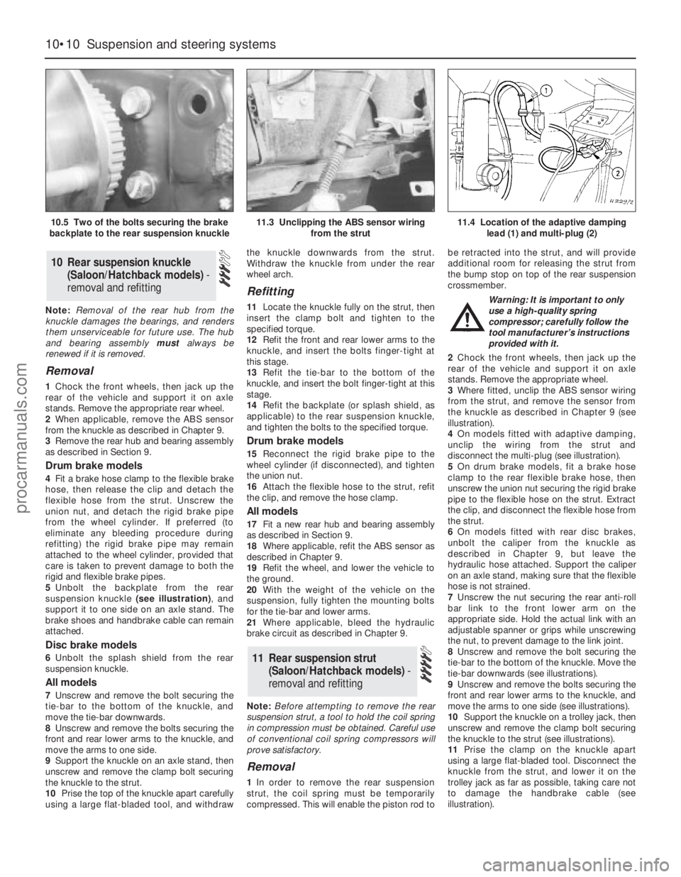
5Unbolt the backplate from the rear
suspension knuckle (see illustration), and
support it to one side on an axle stand. The
brake shoes and handbrake cable can remain
attached.
Disc brake models
6Unbolt the splash shield from the rear
suspension knuckle.
All models
7Unscrew and remove the bolt securing the
tie-bar to the bottom of the knuckle, and
move the tie-bar downwards.
8Unscrew and remove the bolts securing the
front and rear lower arms to the knuckle, and
move the arms to one side.
9Support the knuckle on an axle stand, then
unscrew and remove the clamp bolt securing
the knuckle to the strut.
10Prise the top of the knuckle apart carefully
using a large flat-bladed tool, and withdrawthe knuckle downwards from the strut.
Withdraw the knuckle from under the rear
wheel arch.
Refitting
11Locate the knuckle fully on the strut, then
insert the clamp bolt and tighten to the
specified torque.
12Refit the front and rear lower arms to the
knuckle, and insert the bolts finger-tight at
this stage.
13Refit the tie-bar to the bottom of the
knuckle, and insert the bolt finger-tight at this
stage.
14Refit the backplate (or splash shield, as
applicable) to the rear suspension knuckle,
and tighten the bolts to the specified torque.
Drum brake models
15Reconnect the rigid brake pipe to the
wheel cylinder (if disconnected), and tighten
the union nut.
16Attach the flexible hose to the strut, refit
the clip, and remove the hose clamp.
All models
17Fit a new rear hub and bearing assembly
as described in Section 9.
18Where applicable, refit the ABS sensor as
described in Chapter 9.
19Refit the wheel, and lower the vehicle to
the ground.
20With the weight of the vehicle on the
suspension, fully tighten the mounting bolts
for the tie-bar and lower arms.
21Where applicable, bleed the hydraulic
brake circuit as described in Chapter 9.
Note:Before attempting to remove the rear
suspension strut, a tool to hold the coil spring
in compression must be obtained. Careful use
of conventional coil spring compressors will
prove satisfactory.
Removal
1In order to remove the rear suspension
strut, the coil spring must be temporarily
compressed. This will enable the piston rod tobe retracted into the strut, and will provide
additional room for releasing the strut from
the bump stop on top of the rear suspension
crossmember.
Warning: It is important to only
use a high-quality spring
compressor; carefully follow the
tool manufacturer’s instructions
provided with it.
2Chock the front wheels, then jack up the
rear of the vehicle and support it on axle
stands. Remove the appropriate wheel.
3Where fitted, unclip the ABS sensor wiring
from the strut, and remove the sensor from
the knuckle as described in Chapter 9 (see
illustration).
4On models fitted with adaptive damping,
unclip the wiring from the strut and
disconnect the multi-plug (see illustration).
5On drum brake models, fit a brake hose
clamp to the rear flexible brake hose, then
unscrew the union nut securing the rigid brake
pipe to the flexible hose on the strut. Extract
the clip, and disconnect the flexible hose from
the strut.
6On models fitted with rear disc brakes,
unbolt the caliper from the knuckle as
described in Chapter 9, but leave the
hydraulic hose attached. Support the caliper
on an axle stand, making sure that the flexible
hose is not strained.
7Unscrew the nut securing the rear anti-roll
bar link to the front lower arm on the
appropriate side. Hold the actual link with an
adjustable spanner or grips while unscrewing
the nut, to prevent damage to the link joint.
8Unscrew and remove the bolt securing the
tie-bar to the bottom of the knuckle. Move the
tie-bar downwards (see illustrations).
9Unscrew and remove the bolts securing the
front and rear lower arms to the knuckle, and
move the arms to one side (see illustrations).
10Support the knuckle on a trolley jack, then
unscrew and remove the clamp bolt securing
the knuckle to the strut (see illustrations).
11Prise the clamp on the knuckle apart
using a large flat-bladed tool. Disconnect the
knuckle from the strut, and lower it on the
trolley jack as far as possible, taking care not
to damage the handbrake cable (see
illustration).
11 Rear suspension strut
(Saloon/Hatchback models) -
removal and refitting
10 Rear suspension knuckle
(Saloon/Hatchback models)-
removal and refitting
10•10 Suspension and steering systems
10.5 Two of the bolts securing the brake
backplate to the rear suspension knuckle11.3 Unclipping the ABS sensor wiring
from the strut11.4 Location of the adaptive damping
lead (1) and multi-plug (2)
procarmanuals.com
Page 166 of 279
Refitting
15Locate the strut assembly (together with
the coil spring compressor tool) under the
wheel arch, and locate the bracket on the
bump stop on the rear suspension
crossmember. Insert the two bolts securing
the upper mounting to the underbody tower,
and tighten them to the specified torque.
16Carefully release the coil spring
compressor tool, making sure that the spring
locates correctly in the upper and lower seats,
and that the strut bracket locates on the
crossmember bump stop. The bump stop is
tapered inwards, and the strut bracket should
be fully engaged with it before releasing the
coil spring.
17Raise the knuckle and engage it with the
strut, then insert the clamp bolt and tighten to
the specified torque.
18Reconnect the front and rear lower armsto the knuckle, and finger-tighten the bolts at
this stage.
19Reconnect the tie-bar to the bottom of the
knuckle, and finger-tighten the bolt at this
stage.
20Refit the anti-roll bar link to the lower arm,
and tighten the nut to the specified torque.
21On disc brake models, refit the caliper
bracket to the knuckle, and tighten the
mounting bolts to the specified torque (see
Chapter 9). Make sure that the flexible brake
hose is not twisted.
22On drum brake models, connect the
flexible hose to the strut, insert the clip, then
insert the rigid brake line and tighten the union
nut. Remove the brake hose clamp, then
bleed the hydraulic brake circuit as described
in Chapter 9.
23Where applicable, reconnect the wiring
multi-plug for the adaptive damping, and clip
the wiring to the strut.24Where applicable, refit the ABS sensor as
described in Chapter 9, and clip the wiring to
the strut.
25Refit the wheel, and lower the vehicle to
the ground.
26With the weight of the vehicle on the rear
suspension, fully tighten the lower arm and
tie-bar mounting bolts.
1The procedure is similar to that for the front
suspension strut, and reference should be made
to Section 5. Note that the spring compressor
tools will already be in position on the coil spring
following the removal operation. Refer also to
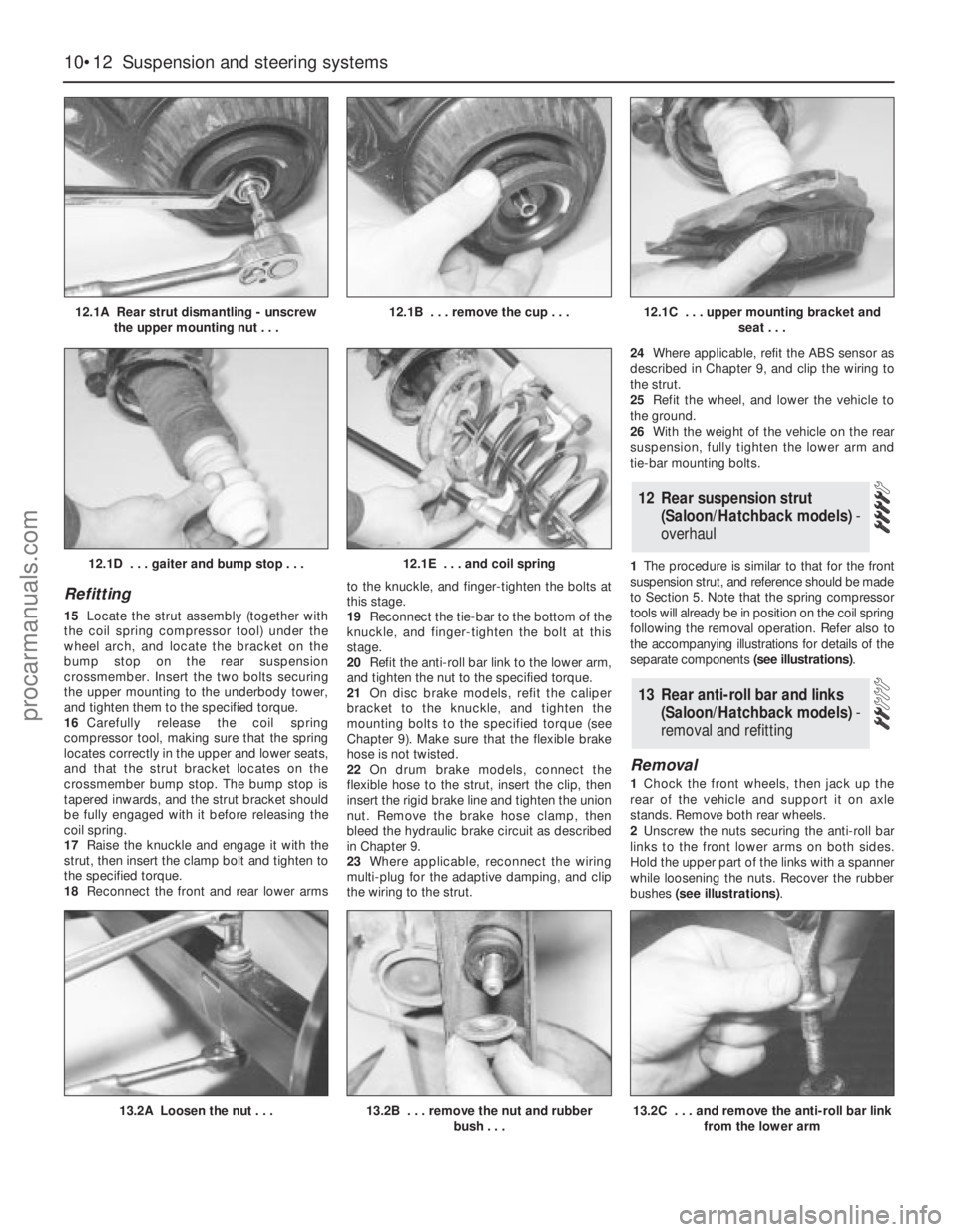
the accompanying illustrations for details of the
separate components (see illustrations).
Removal
1Chock the front wheels, then jack up the
rear of the vehicle and support it on axle
stands. Remove both rear wheels.
2Unscrew the nuts securing the anti-roll bar
links to the front lower arms on both sides.
Hold the upper part of the links with a spanner
while loosening the nuts. Recover the rubber
bushes (see illustrations).
13 Rear anti-roll bar and links
(Saloon/Hatchback models) -
removal and refitting
12 Rear suspension strut
(Saloon/Hatchback models)-
overhaul
10•12 Suspension and steering systems
12.1A Rear strut dismantling - unscrew
the upper mounting nut . . .12.1B . . . remove the cup . . .12.1C . . . upper mounting bracket and
seat . . .
13.2A Loosen the nut . . .13.2B . . . remove the nut and rubber
bush . . .
12.1D . . . gaiter and bump stop . . .12.1E . . . and coil spring
13.2C . . . and remove the anti-roll bar link
from the lower arm
procarmanuals.com
Page 167 of 279
3Unscrew the bolts securing the anti-roll bar
mounting clamps to the rear suspension
crossmember, then unhook the clamps and
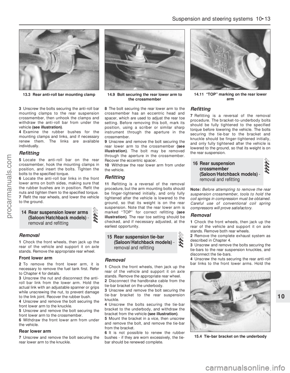
withdraw the anti-roll bar from under the
vehicle (see illustration).
4Examine the rubber bushes for the
mounting clamps and links, and if necessary
renew them. The links are available
individually.
Refitting
5Locate the anti-roll bar on the rear
crossmember, hook the mounting clamps in
position, and insert the bolts. Tighten the
bolts to the specified torque.
6Locate the anti-roll bar links in the front
lower arms on both sides, making sure that
the rubber bushes are in position. Refit the
nuts and tighten them to the specified torque.
7Refit the rear wheels, and lower the vehicle
to the ground.
Removal
1Chock the front wheels, then jack up the
rear of the vehicle and support it on axle
stands. Remove the appropriate rear wheel.
Front lower arm
2To remove the front lower arm, it is
necessary to remove the fuel tank first. Refer
to Chapter 4 for details.
3Unscrew the nut and disconnect the anti-
roll bar link from the lower arm. Hold the
actual link with an adjustable spanner or grips
while unscrewing the nut, to prevent damage
to the link joint. Recover the rubber bush.
4Unscrew and remove the bolt securing the
front lower arm to the knuckle.
5Unscrew and remove the bolt securing the
front lower arm to the crossmember.
6Withdraw the front lower arm from under
the vehicle.
Rear lower arm
7Unscrew and remove the bolt securing the
rear lower arm to the knuckle.8The bolt securing the rear lower arm to the
crossmember has an eccentric head and
spacer, which are used to adjust the rear toe
setting. Before removing this bolt, mark its
position, using a scriber or similar sharp
instrument through the aperture in the
crossmember.
9Unscrew and remove the bolt securing the
rear lower arm to the crossmember (see
illustration). The bolt may be removed
through the aperture in the crossmember.
Recover the eccentric spacer.
10Withdraw the rear lower arm from under
the vehicle.
Refitting
11Refitting is a reversal of the removal
procedure, but the arm mounting bolts should
be finger-tightened initially, and only fully
tightened after the vehicle is lowered to the
ground, so that its weight is on the rear
suspension. Note that the rear lower arm is
marked “TOP” for correct refitting (see
illustration). The rear toe setting should be
checked, and if necessary adjusted, at the
earliest opportunity.
Removal
1Chock the front wheels, then jack up the
rear of the vehicle and support it on axle
stands. Remove the appropriate rear wheel.
2Disconnect the handbrake cable from the
tie-bar bracket on the underbody.
3Unscrew and remove the bolt securing the
tie-bar bracket to the rear suspension
knuckle.
4Unscrew the bolts securing the tie-bar
bracket to the underbody, and withdraw the
bracket from the vehicle (see illustration).
5Mount the bracket in a vice, then unscrew
and remove the bolt, and remove the tie-bar
from the bracket.
6It is not possible to renew the rubber
bushes - if they are worn excessively, the tie-
bar should be renewed complete.
Refitting
7Refitting is a reversal of the removal
procedure. The bracket-to-underbody bolts
should be fully tightened to the specified
torque before lowering the vehicle. The bolts
securing the tie-bar to the bracket and
knuckle should be finger-tightened initially,
and only fully tightened after the vehicle is
lowered to the ground, so that its weight is on
the rear suspension.
Note:Before attempting to remove the rear
suspension crossmember, tools to hold the
coil springs in compression must be obtained.
Careful use of conventional coil spring
compressors will prove satisfactory.
Removal
1Chock the front wheels, then jack up the
rear of the vehicle and support it on axle
stands. Remove both rear wheels.
2Remove the complete exhaust system as
described in Chapter 4.
3Unscrew and remove the bolts securing the
tie-bars to the rear suspension knuckles, and
disconnect the tie-bars.
4Unscrew the nuts securing the rear anti-roll
bar links to the front lower arms. Hold the
16 Rear suspension
crossmember
(Saloon/Hatchback models) -
removal and refitting
15 Rear suspension tie-bar
(Saloon/Hatchback models) -
removal and refitting
14 Rear suspension lower arms
(Saloon/Hatchback models)-
removal and refitting
Suspension and steering systems 10•13
10
14.11 “TOP” marking on the rear lower
arm
15.4 Tie-bar bracket on the underbody
13.3 Rear anti-roll bar mounting clamp14.9 Bolt securing the rear lower arm to
the crossmember
procarmanuals.com