1993 FORD MONDEO bulb
[x] Cancel search: bulbPage 218 of 279
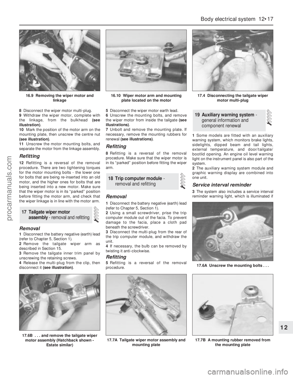
8Disconnect the wiper motor multi-plug.
9Withdraw the wiper motor, complete with
the linkage, from the bulkhead (see
illustration).
10Mark the position of the motor arm on the
mounting plate, then unscrew the centre nut
(see illustration).
11Unscrew the motor mounting bolts, and
separate the motor from the linkage assembly.
Refitting
12Refitting is a reversal of the removal
procedure. There are two tightening torques
for the motor mounting bolts - the lower one
for bolts that are being re-inserted into an old
motor, and the higher ones for bolts that are
being inserted into a new motor. Make sure
that the wiper motor is in its “parked” position
before fitting the motor arm, and check that
the wiper linkage is in line with the motor arm.
Removal
1Disconnect the battery negative (earth) lead
(refer to Chapter 5, Section 1).
2Remove the tailgate wiper arm as
described in Section 15.
3Remove the tailgate inner trim panel by
unscrewing the retaining screws.
4Release the multi-plug from the clip, then
disconnect it (see illustration).5Disconnect the wiper motor earth lead.
6Unscrew the mounting bolts, and remove
the wiper motor from inside the tailgate (see
illustrations).
7Unbolt and remove the mounting plate. If
necessary, remove the mounting rubbers for
renewal (see illustrations).
Refitting
8Refitting is a reversal of the removal
procedure. Make sure that the wiper motor is
in its “parked” position before fitting the wiper
arm.
Removal
1Disconnect the battery negative (earth) lead
(refer to Chapter 5, Section 1).
2Using a small screwdriver, prise the trip
computer module out of the facia. To prevent
damage to the facia, place a cloth pad
beneath the screwdriver.
3Disconnect the multi-plug from the rear of
the trip computer module, and withdraw the
unit.
4If necessary, the bulb can be removed by
twisting it anti-clockwise.
Refitting
5Refitting is a reversal of the removal
procedure.1Some models are fitted with an auxiliary
warning system, which monitors brake lights,
sidelights, dipped beam and tail lights,
external temperature, and door/tailgate/
bootlid opening. An engine oil level warning
light on the instrument panel is also part of the
system.
2The auxiliary warning system module and
graphic warning display are combined into
one unit.
Service interval reminder
3The system also includes a service interval
reminder warning light, which is illuminated if
19 Auxiliary warning system -
general information and
component renewal
18 Trip computer module-
removal and refitting
17 Tailgate wiper motor
assembly - removal and refitting
Body electrical system 12•17
12
17.6B . . . and remove the tailgate wiper
motor assembly (Hatchback shown -
Estate similar)17.7A Tailgate wiper motor assembly and
mounting plate17.7B A mounting rubber removed from
the mounting plate
17.6A Unscrew the mounting bolts . . .
16.9 Removing the wiper motor and
linkage16.10 Wiper motor arm and mounting
plate located on the motor17.4 Disconnecting the tailgate wiper
motor multi-plug
procarmanuals.com
Page 219 of 279
the specified mileage (or time) since the last
service has been reached.
4To reset the service interval system and
turn off the light, a switch inside the glovebox
must be depressed for a minimum of 4
seconds with the ignition switched on. This
should be carried out by a Ford dealer if the
vehicle is still in the warranty period.
Component renewal
5The following paragraphs describe brief
removal procedures for the auxiliary warning
system components. Disconnect the battery
negative (earth) lead before commencing
work (refer to Chapter 5, Section 1). Refitting
procedures are a reversal of removal.
Display warning bulb
6Remove the control assembly.
7Prise off the cover, and pull out the relevant
bulb and bulbholder.
Low air temperature warning sender
unit
8Remove the front bumper.
9Unclip the sender unit and disconnect the
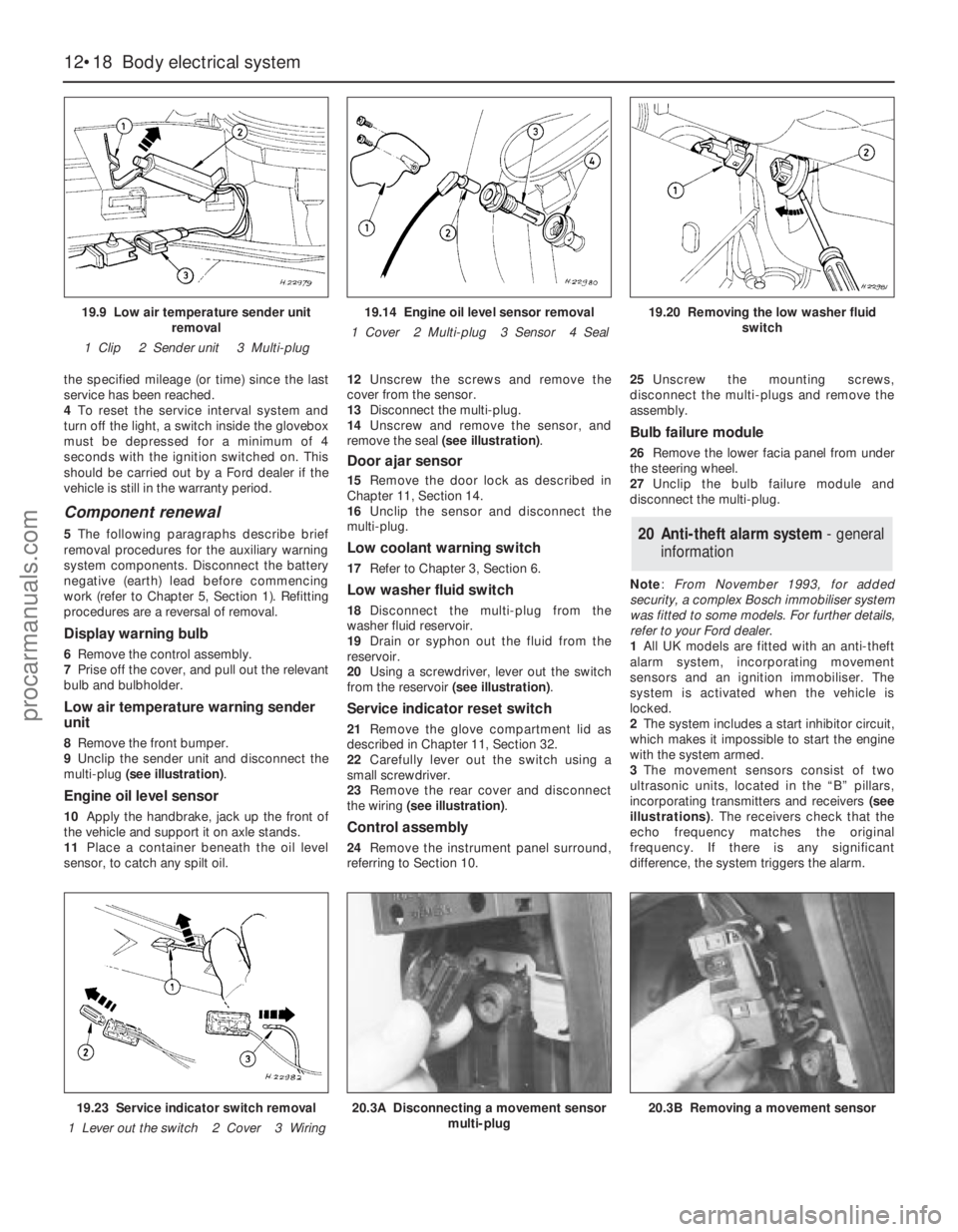
multi-plug (see illustration).
Engine oil level sensor
10Apply the handbrake, jack up the front of
the vehicle and support it on axle stands.
11Place a container beneath the oil level
sensor, to catch any spilt oil.12Unscrew the screws and remove the
cover from the sensor.
13Disconnect the multi-plug.
14Unscrew and remove the sensor, and
remove the seal (see illustration).
Door ajar sensor
15Remove the door lock as described in
Chapter 11, Section 14.
16Unclip the sensor and disconnect the
multi-plug.
Low coolant warning switch
17Refer to Chapter 3, Section 6.
Low washer fluid switch
18Disconnect the multi-plug from the
washer fluid reservoir.
19Drain or syphon out the fluid from the
reservoir.
20Using a screwdriver, lever out the switch
from the reservoir (see illustration).
Service indicator reset switch
21Remove the glove compartment lid as
described in Chapter 11, Section 32.
22Carefully lever out the switch using a
small screwdriver.
23Remove the rear cover and disconnect
the wiring (see illustration).
Control assembly
24Remove the instrument panel surround,
referring to Section 10.25Unscrew the mounting screws,
disconnect the multi-plugs and remove the
assembly.
Bulb failure module
26Remove the lower facia panel from under
the steering wheel.
27Unclip the bulb failure module and
disconnect the multi-plug.
Note: From November 1993, for added
security, a complex Bosch immobiliser system
was fitted to some models. For further details,
refer to your Ford dealer.
1All UK models are fitted with an anti-theft
alarm system, incorporating movement
sensors and an ignition immobiliser. The
system is activated when the vehicle is
locked.
2The system includes a start inhibitor circuit,
which makes it impossible to start the engine
with the system armed.
3The movement sensors consist of two
ultrasonic units, located in the “B” pillars,
incorporating transmitters and receivers (see
illustrations). The receivers check that the
echo frequency matches the original
frequency. If there is any significant
difference, the system triggers the alarm.
20 Anti-theft alarm system- general
information
12•18 Body electrical system
19.9 Low air temperature sender unit
removal
1 Clip 2 Sender unit 3 Multi-plug19.14 Engine oil level sensor removal
1 Cover 2 Multi-plug 3 Sensor 4 Seal19.20 Removing the low washer fluid
switch
19.23 Service indicator switch removal
1 Lever out the switch 2 Cover 3 Wiring20.3A Disconnecting a movement sensor
multi-plug20.3B Removing a movement sensor
procarmanuals.com
Page 249 of 279
12•48 Wiring diagrams
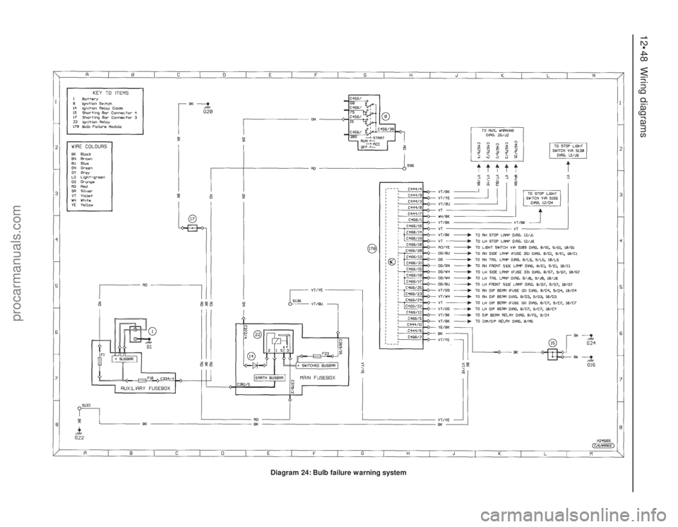
Diagram 24: Bulb failure warning system
procarmanuals.com
Page 264 of 279
Buying spare parts
Spare parts are available from many
sources; for example, Ford garages, other
garages and accessory shops, and motor
factors. Our advice regarding spare part
sources is as follows.
Officially-appointed Ford garages- This is
the best source for parts which are peculiar to
your vehicle, and which are not generally
available (eg complete cylinder heads, internal
transmission components, badges, interior
trim etc). It is also the only place at which you
should buy parts if the vehicle is still under
warranty. To be sure of obtaining the correct
parts, it will be necessary to give the storeman
the full Vehicle Identification Number, and if
possible, to take the old parts along for
positive identification. Many parts are
available under a factory exchange scheme -
any parts returned should always be clean. It
obviously makes good sense to go straight to
the specialists on your vehicle for this type of
part, as they are best equipped to supply you.
Other garages and accessory shops- These
are often very good places to buy materials
and components needed for the maintenance
of your vehicle (eg oil filters, spark plugs,
bulbs, drivebelts, oils and greases, touch-up
paint, filler paste, etc). They also sell general
accessories, usually have convenient opening
hours, charge lower prices, and can often be
found not far from home.
Motor factors- Good factors will stock all
the more important components which wear
out comparatively quickly (eg exhaust
systems, brake pads, seals and hydraulic
parts, clutch components, bearing shells,
pistons, valves etc). Motor factors will often
provide new or reconditioned components on
a part-exchange basis - this can save a
considerable amount of money.
Vehicle identification numbers
Modifications are a continuing and
unpublicised process in vehicle manufacture,
quite apart from major model changes. Spare
parts manuals and lists are compiled upon a
numerical basis, the appropriate identification
number or code being essential to correct
identification of the component concerned.
When ordering spare parts, always give asmuch information as possible. Quote the
vehicle model, year of manufacture, Vehicle
Identification Number and engine numbers, as
appropriate.
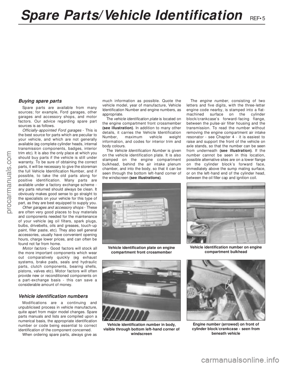
The vehicle identification plateis located on
the engine compartment front crossmember
(see illustration). In addition to many other
details, it carries the Vehicle Identification
Number, maximum vehicle weight
information, and codes for interior trim and
body colours.
The Vehicle Identification Numberis given
on the vehicle identification plate. It is also
stamped on the engine compartment
bulkhead, behind the air intake plenum
chamber, and into the body, so that it can be
seen through the bottom left-hand corner of
the windscreen (see illustrations).The engine number, consisting of two
letters and five digits, with the three-letter
engine code nearby, is stamped into a flat-
machined surface on the cylinder
block/crankcase’s forward-facing flange,
between the pulse-air filter housing and the
transmission. To read the number without
removing the engine compartment air intake
resonator - see Chapter 4 - it is easiest to
raise and support the front of the vehicle on
axle stands, so that the number can be seen
from underneath (see illustration). If the
number cannot be seen in this location,
possible alternative sites are on a lower flange
on the cylinder block’s forward face,
immediately above the sump mating surface,
or on the left-hand end of the cylinder head,
between the oil filler cap and ignition coil.
REF•5
Vehicle identification plate on engine
compartment front crossmember
Vehicle identification number in body,
visible through bottom left-hand corner of
windscreen
Vehicle identification number on engine
compartment bulkhead
Engine number (arrowed) on front of
cylinder block/crankcase - seen from
beneath vehicle
Spare Parts/Vehicle Identification
procarmanuals.com
Page 271 of 279
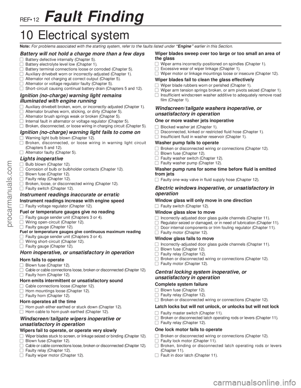
REF•12
Battery will not hold a charge more than a few days
m mBattery defective internally (Chapter 5).
m mBattery electrolyte level low (Chapter 1).
m mBattery terminal connections loose or corroded (Chapter 5).
m mAuxiliary drivebelt worn or incorrectly-adjusted (Chapter 1).
m mAlternator not charging at correct output (Chapter 5).
m mAlternator or voltage regulator faulty (Chapter 5).
m mShort-circuit causing continual battery drain (Chapters 5 and 12).
Ignition (no-charge) warning light remains
illuminated with engine running
m mAuxiliary drivebelt broken, worn, or incorrectly-adjusted (Chapter 1).
m mAlternator brushes worn, sticking, or dirty (Chapter 5).
m mAlternator brush springs weak or broken (Chapter 5).
m mInternal fault in alternator or voltage regulator (Chapter 5).
m mBroken, disconnected, or loose wiring in charging circuit (Chapter 5).
Ignition (no-charge) warning light fails to come on
m
mWarning light bulb blown (Chapter 12).
m mBroken, disconnected, or loose wiring in warning light circuit
(Chapters 5 and 12).
m mAlternator faulty (Chapter 5).
Lights inoperative
m
mBulb blown (Chapter 12).
m mCorrosion of bulb or bulbholder contacts (Chapter 12).
m mBlown fuse (Chapter 12).
m mFaulty relay (Chapter 12).
m mBroken, loose, or disconnected wiring (Chapter 12).
m mFaulty switch (Chapter 12).
Instrument readings inaccurate or erratic
Instrument readings increase with engine speed
m
mFaulty voltage regulator (Chapter 12).
Fuel or temperature gauges give no reading
m
mFaulty gauge sender unit (Chapters 3 or 4).
m mWiring open-circuit (Chapter 12).
m mFaulty gauge (Chapter 12).
Fuel or temperature gauges give continuous maximum reading
m mFaulty gauge sender unit (Chapters 3 or 4).
m mWiring short-circuit (Chapter 12).
m mFaulty gauge (Chapter 12).
Horn inoperative, or unsatisfactory in operation
Horn fails to operate
m
mBlown fuse (Chapter 12).
m mCable or cable connections loose, broken or disconnected (Chapter 12).
m mFaulty horn (Chapter 12).
Horn emits intermittent or unsatisfactory sound
m
mCable connections loose (Chapter 12).
m mHorn mountings loose (Chapter 12).
m mFaulty horn (Chapter 12).
Horn operates all the time
m
mHorn push either earthed or stuck down (Chapter 12).
m mHorn cable to horn push earthed (Chapter 12).
Windscreen/tailgate wipers inoperative or
unsatisfactory in operation
Wipers fail to operate, or operate very slowly
m mWiper blades stuck to screen, or linkage seized or binding (Chapter 12).
m mBlown fuse (Chapter 12).
m mCable or cable connections loose, broken or disconnected (Chapter 12).
m mFaulty relay (Chapter 12).
m mFaulty wiper motor (Chapter 12).
Wiper blades sweep over too large or too small an area of
the glass
m mWiper arms incorrectly-positioned on spindles (Chapter 1).
m mExcessive wear of wiper linkage (Chapter 1).
m mWiper motor or linkage mountings loose or insecure (Chapter 12).
Wiper blades fail to clean the glass effectively
m
mWiper blade rubbers worn or perished (Chapter 1).
m mWiper arm tension springs broken, or arm pivots seized (Chapter 1).
m mInsufficient windscreen washer additive to adequately remove road
film (Chapter 1).
Windscreen/tailgate washers inoperative, or
unsatisfactory in operation
One or more washer jets inoperative
m mBlocked washer jet (Chapter 1).
m mDisconnected, kinked or restricted fluid hose (Chapter 1).
m mInsufficient fluid in washer reservoir (Chapter 1).
Washer pump fails to operate
m
mBroken or disconnected wiring or connections (Chapter 12).
m mBlown fuse (Chapter 12).
m mFaulty washer switch (Chapter 12).
m mFaulty washer pump (Chapter 12).
Washer pump runs for some time before fluid is emitted
from jets
m mFaulty one-way valve in fluid supply hose (Chapter 12).
Electric windows inoperative, or unsatisfactory in
operation
Window glass will only move in one direction
m mFaulty switch (Chapter 12).
Window glass slow to move
m
mIncorrectly-adjusted door glass guide channels (Chapter 11).
m mRegulator seized or damaged, or in need of lubrication (Chapter 11).
m mDoor internal components or trim fouling regulator (Chapter 11).
m mFaulty motor (Chapter 12).
Window glass fails to move
m
mIncorrectly-adjusted door glass guide channels (Chapter 11).
m mBlown fuse (Chapter 12).
m mFaulty relay (Chapter 12).
m mBroken or disconnected wiring or connections (Chapter 12).
m mFaulty motor (Chapter 12).
Central locking system inoperative, or
unsatisfactory in operation
Complete system failure
m mBlown fuse (Chapter 12).
m mFaulty relay (Chapter 12).
m mBroken or disconnected wiring or connections (Chapter 12).
Latch locks but will not unlock, or unlocks but will not lock
m
mFaulty master switch (Chapter 11).
m mBroken or disconnected latch operating rods or levers (Chapter 11).
m mFaulty relay (Chapter 12).
One lock motor fails to operate
m
mBroken or disconnected wiring or connections (Chapter 12).
m mFaulty lock motor (Chapter 11).
m mBroken, binding or disconnected latch operating rods or levers
(Chapter 11).
m mFault in door latch (Chapter 11).
Fault Finding
10 Electrical system
Note:For problems associated with the starting system, refer to the faults listed under “Engine”earlier in this Section.
procarmanuals.com
Page 276 of 279
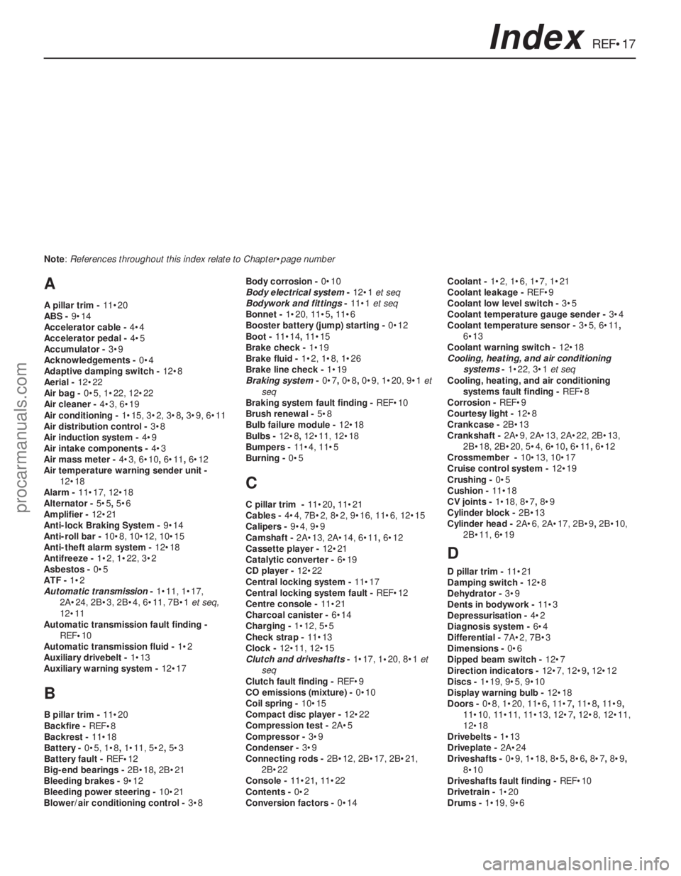
REF•17Index
A
A pillar trim - 11•20
ABS - 9•14
Accelerator cable - 4•4
Accelerator pedal - 4•5
Accumulator - 3•9
Acknowledgements - 0•4
Adaptive damping switch - 12•8
Aerial - 12•22
Air bag - 0•5, 1•22, 12•22
Air cleaner - 4•3, 6•19
Air conditioning - 1•15, 3•2, 3•8, 3•9, 6•11
Air distribution control - 3•8
Air induction system - 4•9
Air intake components - 4•3
Air mass meter - 4•3, 6•10, 6•11, 6•12
Air temperature warning sender unit -
12•18
Alarm - 11•17, 12•18
Alternator - 5•5, 5•6
Amplifier - 12•21
Anti-lock Braking System - 9•14
Anti-roll bar - 10•8, 10•12, 10•15
Anti-theft alarm system - 12•18
Antifreeze - 1•2, 1•22, 3•2
Asbestos - 0•5
ATF - 1•2
Automatic transmission- 1•11, 1•17,
2A•24, 2B•3, 2B•4, 6•11, 7B•1et seq,
12•11
Automatic transmission fault finding -
REF•10
Automatic transmission fluid - 1•2
Auxiliary drivebelt - 1•13
Auxiliary warning system - 12•17
B
B pillar trim - 11•20
Backfire - REF•8
Backrest - 11•18
Battery - 0•5, 1•8, 1•11, 5•2, 5•3
Battery fault - REF•12
Big-end bearings - 2B•18, 2B•21
Bleeding brakes - 9•12
Bleeding power steering - 10•21
Blower/air conditioning control - 3•8Body corrosion - 0•10
Body electrical system- 12•1et seq
Bodywork and fittings- 11•1et seq
Bonnet - 1•20, 11•5, 11•6
Booster battery (jump) starting - 0•12
Boot - 11•14, 11•15
Brake check - 1•19
Brake fluid - 1•2, 1•8, 1•26
Brake line check - 1•19
Braking system- 0•7, 0•8, 0•9, 1•20, 9•1et
seq
Braking system fault finding - REF•10
Brush renewal - 5•8
Bulb failure module - 12•18
Bulbs - 12•8, 12•11, 12•18
Bumpers - 11•4, 11•5
Burning - 0•5
C
C pillar trim - 11•20, 11•21
Cables - 4•4, 7B•2, 8•2, 9•16, 11•6, 12•15
Calipers - 9•4, 9•9
Camshaft - 2A•13, 2A•14, 6•11, 6•12
Cassette player - 12•21
Catalytic converter - 6•19
CD player - 12•22
Central locking system - 11•17
Central locking system fault - REF•12
Centre console - 11•21
Charcoal canister - 6•14
Charging - 1•12, 5•5
Check strap - 11•13
Clock - 12•11, 12•15
Clutch and driveshafts- 1•17, 1•20, 8•1et
seq
Clutch fault finding - REF•9
CO emissions (mixture) - 0•10
Coil spring - 10•15
Compact disc player - 12•22
Compression test - 2A•5
Compressor - 3•9
Condenser - 3•9
Connecting rods - 2B•12, 2B•17, 2B•21,
2B•22
Console - 11•21, 11•22
Contents - 0•2
Conversion factors - 0•14Coolant - 1•2, 1•6, 1•7, 1•21
Coolant leakage - REF•9
Coolant low level switch - 3•5
Coolant temperature gauge sender - 3•4
Coolant temperature sensor - 3•5, 6•11,
6•13
Coolant warning switch - 12•18
Cooling, heating, and air conditioning
systems- 1•22, 3•1et seq
Cooling, heating, and air conditioning
systems fault finding - REF•8
Corrosion - REF•9
Courtesy light - 12•8
Crankcase - 2B•13
Crankshaft - 2A•9, 2A•13, 2A•22, 2B•13,
2B•18, 2B•20, 5•4, 6•10, 6•11, 6•12
Crossmember - 10•13, 10•17
Cruise control system - 12•19
Crushing - 0•5
Cushion - 11•18
CV joints - 1•18, 8•7, 8•9
Cylinder block - 2B•13
Cylinder head - 2A•6, 2A•17, 2B•9, 2B•10,
2B•11, 6•19
D
D pillar trim - 11•21
Damping switch - 12•8
Dehydrator - 3•9
Dents in bodywork - 11•3
Depressurisation - 4•2
Diagnosis system - 6•4
Differential - 7A•2, 7B•3
Dimensions - 0•6
Dipped beam switch - 12•7
Direction indicators - 12•7, 12•9, 12•12
Discs - 1•19, 9•5, 9•10
Display warning bulb - 12•18
Doors - 0•8, 1•20, 11•6, 11•7, 11•8, 11•9,
11•10, 11•11, 11•13, 12•7, 12•8, 12•11,
12•18
Drivebelts - 1•13
Driveplate - 2A•24
Driveshafts - 0•9, 1•18, 8•5, 8•6, 8•7, 8•9,
8•10
Driveshafts fault finding - REF•10
Drivetrain - 1•20
Drums - 1•19, 9•6 Note: References throughout this index relate to Chapter•page number
procarmanuals.com