1993 FORD MONDEO brake sensor
[x] Cancel search: brake sensorPage 164 of 279
Note:Removal of the rear hub from the
knuckle damages the bearings, and renders
them unserviceable for future use. The hub
and bearing assembly mustalways be
renewed if it is removed.
Removal
1Chock the front wheels, then jack up the
rear of the vehicle and support it on axle
stands. Remove the appropriate rear wheel.
2When applicable, remove the ABS sensor
from the knuckle as described in Chapter 9.
3Remove the rear hub and bearing assembly
as described in Section 9.
Drum brake models
4Fit a brake hose clamp to the flexible brake
hose, then release the clip and detach the
flexible hose from the strut. Unscrew the
union nut, and detach the rigid brake pipe
from the wheel cylinder. If preferred (to
eliminate any bleeding procedure during
refitting) the rigid brake pipe may remain
attached to the wheel cylinder, provided that
care is taken to prevent damage to both the
rigid and flexible brake pipes.
5Unbolt the backplate from the rear
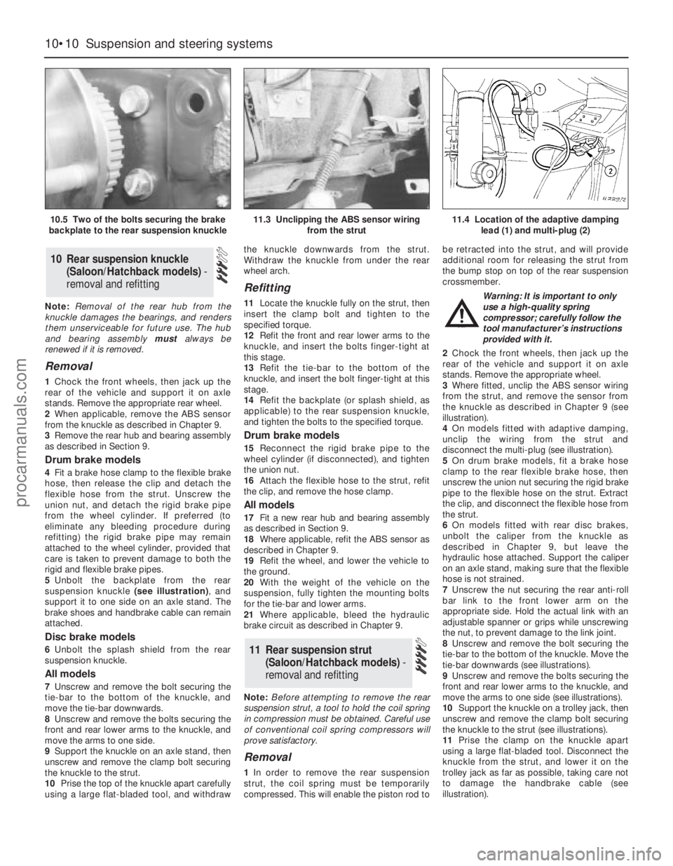
suspension knuckle (see illustration), and
support it to one side on an axle stand. The
brake shoes and handbrake cable can remain
attached.
Disc brake models
6Unbolt the splash shield from the rear
suspension knuckle.
All models
7Unscrew and remove the bolt securing the
tie-bar to the bottom of the knuckle, and
move the tie-bar downwards.
8Unscrew and remove the bolts securing the
front and rear lower arms to the knuckle, and
move the arms to one side.
9Support the knuckle on an axle stand, then
unscrew and remove the clamp bolt securing
the knuckle to the strut.
10Prise the top of the knuckle apart carefully
using a large flat-bladed tool, and withdrawthe knuckle downwards from the strut.
Withdraw the knuckle from under the rear
wheel arch.
Refitting
11Locate the knuckle fully on the strut, then
insert the clamp bolt and tighten to the
specified torque.
12Refit the front and rear lower arms to the
knuckle, and insert the bolts finger-tight at
this stage.
13Refit the tie-bar to the bottom of the
knuckle, and insert the bolt finger-tight at this
stage.
14Refit the backplate (or splash shield, as
applicable) to the rear suspension knuckle,
and tighten the bolts to the specified torque.
Drum brake models
15Reconnect the rigid brake pipe to the
wheel cylinder (if disconnected), and tighten
the union nut.
16Attach the flexible hose to the strut, refit
the clip, and remove the hose clamp.
All models
17Fit a new rear hub and bearing assembly
as described in Section 9.
18Where applicable, refit the ABS sensor as
described in Chapter 9.
19Refit the wheel, and lower the vehicle to
the ground.
20With the weight of the vehicle on the
suspension, fully tighten the mounting bolts
for the tie-bar and lower arms.
21Where applicable, bleed the hydraulic
brake circuit as described in Chapter 9.
Note:Before attempting to remove the rear
suspension strut, a tool to hold the coil spring
in compression must be obtained. Careful use
of conventional coil spring compressors will
prove satisfactory.
Removal
1In order to remove the rear suspension
strut, the coil spring must be temporarily
compressed. This will enable the piston rod tobe retracted into the strut, and will provide
additional room for releasing the strut from
the bump stop on top of the rear suspension
crossmember.
Warning: It is important to only
use a high-quality spring
compressor; carefully follow the
tool manufacturer’s instructions
provided with it.
2Chock the front wheels, then jack up the
rear of the vehicle and support it on axle
stands. Remove the appropriate wheel.
3Where fitted, unclip the ABS sensor wiring
from the strut, and remove the sensor from
the knuckle as described in Chapter 9 (see
illustration).
4On models fitted with adaptive damping,
unclip the wiring from the strut and
disconnect the multi-plug (see illustration).
5On drum brake models, fit a brake hose
clamp to the rear flexible brake hose, then
unscrew the union nut securing the rigid brake
pipe to the flexible hose on the strut. Extract
the clip, and disconnect the flexible hose from
the strut.
6On models fitted with rear disc brakes,
unbolt the caliper from the knuckle as
described in Chapter 9, but leave the
hydraulic hose attached. Support the caliper
on an axle stand, making sure that the flexible
hose is not strained.
7Unscrew the nut securing the rear anti-roll
bar link to the front lower arm on the
appropriate side. Hold the actual link with an
adjustable spanner or grips while unscrewing
the nut, to prevent damage to the link joint.
8Unscrew and remove the bolt securing the
tie-bar to the bottom of the knuckle. Move the
tie-bar downwards (see illustrations).
9Unscrew and remove the bolts securing the
front and rear lower arms to the knuckle, and
move the arms to one side (see illustrations).
10Support the knuckle on a trolley jack, then
unscrew and remove the clamp bolt securing
the knuckle to the strut (see illustrations).
11Prise the clamp on the knuckle apart
using a large flat-bladed tool. Disconnect the
knuckle from the strut, and lower it on the
trolley jack as far as possible, taking care not
to damage the handbrake cable (see
illustration).
11 Rear suspension strut
(Saloon/Hatchback models) -
removal and refitting
10 Rear suspension knuckle
(Saloon/Hatchback models)-
removal and refitting
10•10 Suspension and steering systems
10.5 Two of the bolts securing the brake
backplate to the rear suspension knuckle11.3 Unclipping the ABS sensor wiring
from the strut11.4 Location of the adaptive damping
lead (1) and multi-plug (2)
procarmanuals.com
Page 166 of 279
Refitting
15Locate the strut assembly (together with
the coil spring compressor tool) under the
wheel arch, and locate the bracket on the
bump stop on the rear suspension
crossmember. Insert the two bolts securing
the upper mounting to the underbody tower,
and tighten them to the specified torque.
16Carefully release the coil spring
compressor tool, making sure that the spring
locates correctly in the upper and lower seats,
and that the strut bracket locates on the
crossmember bump stop. The bump stop is
tapered inwards, and the strut bracket should
be fully engaged with it before releasing the
coil spring.
17Raise the knuckle and engage it with the
strut, then insert the clamp bolt and tighten to
the specified torque.
18Reconnect the front and rear lower armsto the knuckle, and finger-tighten the bolts at
this stage.
19Reconnect the tie-bar to the bottom of the
knuckle, and finger-tighten the bolt at this
stage.
20Refit the anti-roll bar link to the lower arm,
and tighten the nut to the specified torque.
21On disc brake models, refit the caliper
bracket to the knuckle, and tighten the
mounting bolts to the specified torque (see
Chapter 9). Make sure that the flexible brake
hose is not twisted.
22On drum brake models, connect the
flexible hose to the strut, insert the clip, then
insert the rigid brake line and tighten the union
nut. Remove the brake hose clamp, then
bleed the hydraulic brake circuit as described
in Chapter 9.
23Where applicable, reconnect the wiring
multi-plug for the adaptive damping, and clip
the wiring to the strut.24Where applicable, refit the ABS sensor as
described in Chapter 9, and clip the wiring to
the strut.
25Refit the wheel, and lower the vehicle to
the ground.
26With the weight of the vehicle on the rear
suspension, fully tighten the lower arm and
tie-bar mounting bolts.
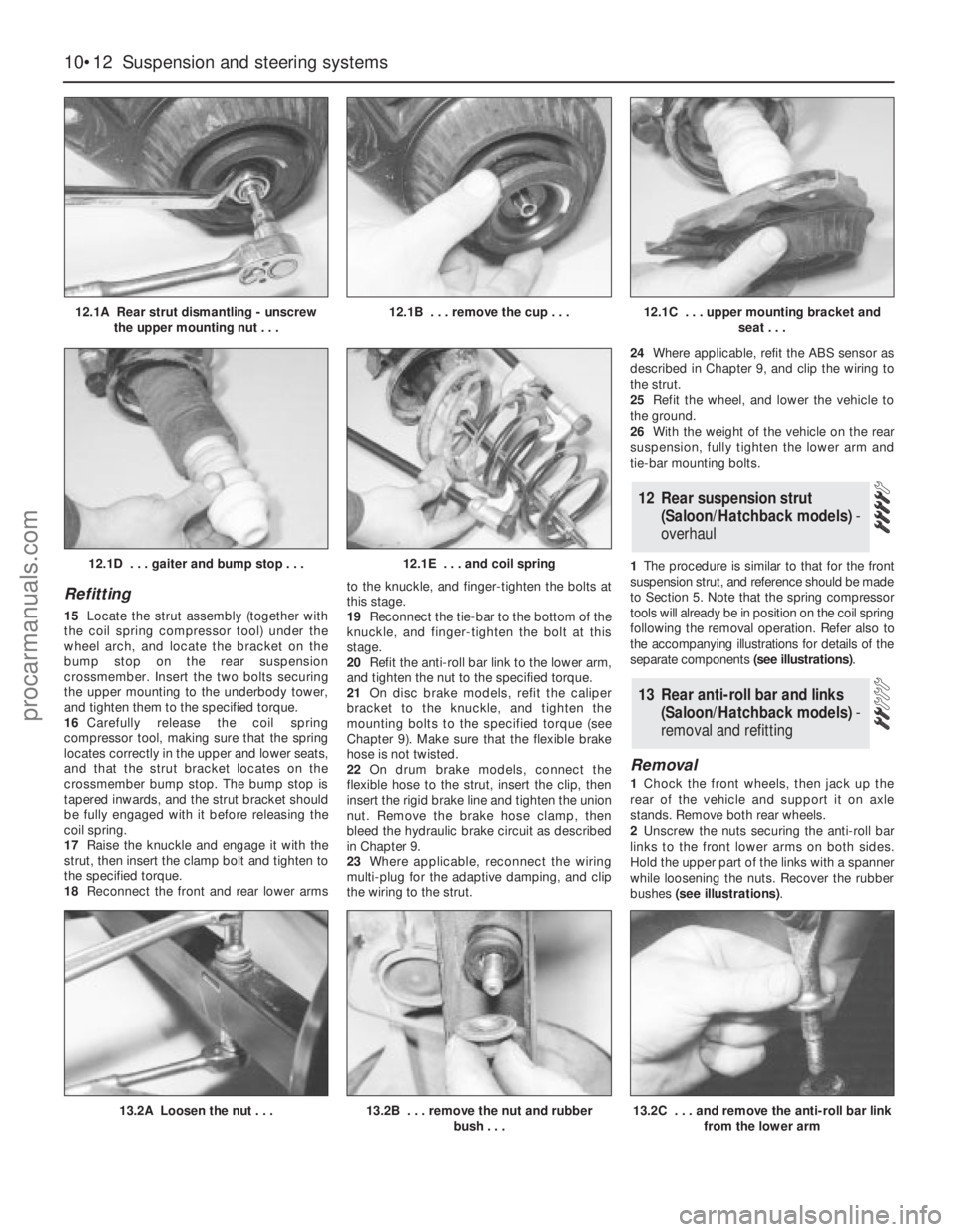
1The procedure is similar to that for the front
suspension strut, and reference should be made
to Section 5. Note that the spring compressor
tools will already be in position on the coil spring
following the removal operation. Refer also to
the accompanying illustrations for details of the
separate components (see illustrations).
Removal
1Chock the front wheels, then jack up the
rear of the vehicle and support it on axle
stands. Remove both rear wheels.
2Unscrew the nuts securing the anti-roll bar
links to the front lower arms on both sides.
Hold the upper part of the links with a spanner
while loosening the nuts. Recover the rubber
bushes (see illustrations).
13 Rear anti-roll bar and links
(Saloon/Hatchback models) -
removal and refitting
12 Rear suspension strut
(Saloon/Hatchback models)-
overhaul
10•12 Suspension and steering systems
12.1A Rear strut dismantling - unscrew
the upper mounting nut . . .12.1B . . . remove the cup . . .12.1C . . . upper mounting bracket and
seat . . .
13.2A Loosen the nut . . .13.2B . . . remove the nut and rubber
bush . . .
12.1D . . . gaiter and bump stop . . .12.1E . . . and coil spring
13.2C . . . and remove the anti-roll bar link
from the lower arm
procarmanuals.com
Page 168 of 279
actual links stationary while the nuts are being
unscrewed, to prevent damage to the joints.
Swivel the anti-roll bar upwards, and recover
the rubber bushes.
5Where applicable, remove the ABS wheel
sensor from the rear suspension knuckle as
described in Chapter 9.
6Unscrew and remove the bolts, and
disconnect both lower arms from the rear
suspension knuckle.
7To allow the rear suspension struts to be
released from the rubber stops on the top of
the crossmember, it is necessary to fit coil
spring compressor tools to both of the rear
coil springs, and compress them until all
tension is removed from the upper and lower
mountings.
Warning: It is important to only
use high-quality spring
compressors, and to carefully
follow the tool manufacturer’s
instructions provided with them. With the
compressor tools fitted, support the struts
to one side.
8Support the rear suspension crossmember
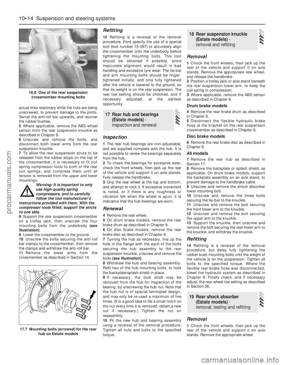
on a trolley jack, then unscrew the four
mounting bolts from the underbody (see
illustration).
9Lower the crossmember to the ground.
10Unscrew the bolts securing the anti-roll
bar clamps to the crossmember, then remove
the clamps and withdraw the anti-roll bar.
11Remove the lower arms from the
crossmember as described in Section 14.
Refitting
12Refitting is a reversal of the removal
procedure. Ford specify the use of a special
tool (tool number 15-097) to accurately align
the crossmember onto the underbody before
tightening the mounting bolts. This tool
should be obtained if possible, since
inaccurate alignment would result in bad
handling and excessive tyre wear. The tie-bar
and arm mounting bolts should be finger-
tightened initially, and only fully tightened
after the vehicle is lowered to the ground, so
that its weight is on the rear suspension. The
rear toe setting should be checked, and if
necessary adjusted, at the earliest
opportunity.
Inspection
1The rear hub bearings are non-adjustable,
and are supplied complete with the hub. It is
not possible to renew the bearings separately
from the hub.
2To check the bearings for excessive wear,
chock the front wheels, then jack up the rear
of the vehicle and support it on axle stands.
Fully release the handbrake.
3Grip the rear wheel at the top and bottom,
and attempt to rock it. If excessive movement
is noted, or if there is any roughness or
vibration felt when the wheel is spun, it is
indicative that the hub bearings are worn.
Renewal
4Remove the rear wheel.
5On drum brake models, remove the rear
brake drum as described in Chapter 9.
6On disc brake models, remove the rear
brake disc as described in Chapter 9.
7Turning the hub as necessary, line up the
hole in the flange with the each of the bolts
securing the hub assembly to the rear
suspension knuckle; unscrew and remove the
bolts (see illustration).
8Withdraw the hub and bearing assembly.
Refit two of the hub mounting bolts, to hold
the backplate/splash shield in place.
9If necessary, the stub shaft may be
removed from the hub for inspection of the
bearing, by unscrewing the hub nut. Note that
the hub nut is of special laminated design,
and may only be re-used a maximum of five
times. (It is a good idea to file a small notch on
the nut every time it is removed; obtain a new
nut if necessary.) Tighten the nut on
reassembly.
10Fit the new hub and bearing assembly
using a reversal of the removal procedure.
Tighten all nuts and bolts to the specified
torque.
Removal
1Chock the front wheels, then jack up the
rear of the vehicle and support it on axle
stands. Remove the appropriate rear wheel,
and release the handbrake.
2Position a trolley jack or axle stand beneath
the rear suspension lower arm, to keep the
coil spring in compression.
3Where applicable, remove the ABS sensor
as described in Chapter 9.
Drum brake models
4Remove the rear brake drum as described
in Chapter 9.
5Disconnect the flexible hydraulic brake
hose at the bracket on the rear suspension
crossmember as described in Chapter 9.
Disc brake models
6Remove the rear brake disc as described in
Chapter 9.
All models
7Remove the rear hub as described in
Section 17.
8Remove the backplate or splash shield, as
applicable. On drum brake models, support
the backplate assembly on an axle stand, to
prevent damage to the handbrake cable.
9Unscrew and remove the shock absorber
lower mounting bolt.
10Unscrew and remove the three bolts
securing the tie-bar to the knuckle.
11Unscrew and remove the bolt securing
the front lower arm to the knuckle.
12Unscrew and remove the bolt securing
the upper arm to the knuckle.
13Support the knuckle, then unscrew and
remove the bolt securing the rear lower arm to
the knuckle, and withdraw the knuckle.
Refitting
14Refitting is a reversal of the removal
procedure, but delay fully tightening the
rubber bush mounting bolts until the weight of
the vehicle is on the suspension. Tighten all
bolts to the specified torque. Where the
flexible rear brake hose was disconnected,
bleed the hydraulic system as described in
Chapter 9. Finally check, and if necessary
adjust, the rear wheel toe setting as described
in Section 36.
Removal
1Chock the front wheels, then jack up the
rear of the vehicle and support it on axle
stands. Remove the appropriate wheel.
19 Rear shock absorber
(Estate models) -
removal, testing and refitting
18 Rear suspension knuckle
(Estate models) -
removal and refitting
17 Rear hub and bearings
(Estate models) -
inspection and renewal
10•14 Suspension and steering systems
16.8 One of the rear suspension
crossmember mounting bolts
17.7 Mounting bolts (arrowed) for the rear
hub on Estate models
procarmanuals.com
Page 171 of 279
2Using a trolley jack, support the rear lower
arm beneath the coil spring position.
3Unscrew and remove the bolt securing the
rear shock absorber to the knuckle.
4Where applicable, release the ABS wheel
sensor lead from the tie-bar.
5Detach the handbrake cable from the tie-
bar bracket.
6Refer to Chapter 9, and disconnect the
handbrake cable from the rear brake shoes or
rear caliper, as applicable. Pass the cable
through the hole in the tie-bar.
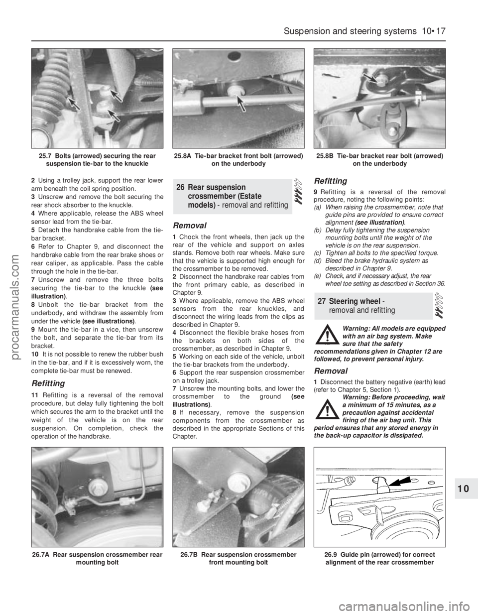
7Unscrew and remove the three bolts
securing the tie-bar to the knuckle (see
illustration).
8Unbolt the tie-bar bracket from the
underbody, and withdraw the assembly from
under the vehicle (see illustrations).
9Mount the tie-bar in a vice, then unscrew
the bolt, and separate the tie-bar from its
bracket.
10It is not possible to renew the rubber bush
in the tie-bar, and if it is excessively worn, the
complete tie-bar must be renewed.
Refitting
11Refitting is a reversal of the removal
procedure, but delay fully tightening the bolt
which secures the arm to the bracket until the
weight of the vehicle is on the rear
suspension. On completion, check the
operation of the handbrake.
Removal
1Chock the front wheels, then jack up the
rear of the vehicle and support on axles
stands. Remove both rear wheels. Make sure
that the vehicle is supported high enough for
the crossmember to be removed.
2Disconnect the handbrake rear cables from
the front primary cable, as described in
Chapter 9.
3Where applicable, remove the ABS wheel
sensors from the rear knuckles, and
disconnect the wiring leads from the clips as
described in Chapter 9.
4Disconnect the flexible brake hoses from
the brackets on both sides of the
crossmember, as described in Chapter 9.
5Working on each side of the vehicle, unbolt
the tie-bar brackets from the underbody.
6Support the rear suspension crossmember
on a trolley jack.
7Unscrew the mounting bolts, and lower the
crossmember to the ground (see
illustrations).
8If necessary, remove the suspension
components from the crossmember as
described in the appropriate Sections of this
Chapter.
Refitting
9Refitting is a reversal of the removal
procedure, noting the following points:
(a) When raising the crossmember, note that
guide pins are provided to ensure correct
alignment (see illustration).
(b) Delay fully tightening the suspension
mounting bolts until the weight of the
vehicle is on the rear suspension.
(c) Tighten all bolts to the specified torque.
(d) Bleed the brake hydraulic system as
described in Chapter 9.
(e) Check, and if necessary adjust, the rear
wheel toe setting as described in Section 36.
Warning: All models are equipped
with an air bag system. Make
sure that the safety
recommendations given in Chapter 12 are
followed, to prevent personal injury.
Removal
1Disconnect the battery negative (earth) lead
(refer to Chapter 5, Section 1).
Warning: Before proceeding, wait
a minimum of 15 minutes, as a
precaution against accidental
firing of the air bag unit. This
period ensures that any stored energy in
the back-up capacitor is dissipated.
27 Steering wheel -
removal and refitting
26 Rear suspension
crossmember (Estate
models) - removal and refitting
Suspension and steering systems 10•17
10
26.7A Rear suspension crossmember rear
mounting bolt26.7B Rear suspension crossmember
front mounting bolt26.9 Guide pin (arrowed) for correct
alignment of the rear crossmember
25.7 Bolts (arrowed) securing the rear
suspension tie-bar to the knuckle25.8A Tie-bar bracket front bolt (arrowed)
on the underbody25.8B Tie-bar bracket rear bolt (arrowed)
on the underbody
procarmanuals.com
Page 216 of 279
6Similarly remove the fuel gauge and
temperature gauge by unscrewing the single
screws.
7Remove all the pin contacts.
8Using a small punch, push in the multi-plug
securing pins, and remove the multi-plugs.
9Carefully lift the printed circuit from the
location dowels on the housing, taking care
not to damage it.
Refitting
10Refitting is a reversal of the removal
procedure.
Removal
1Remove the windscreen wiper arms as
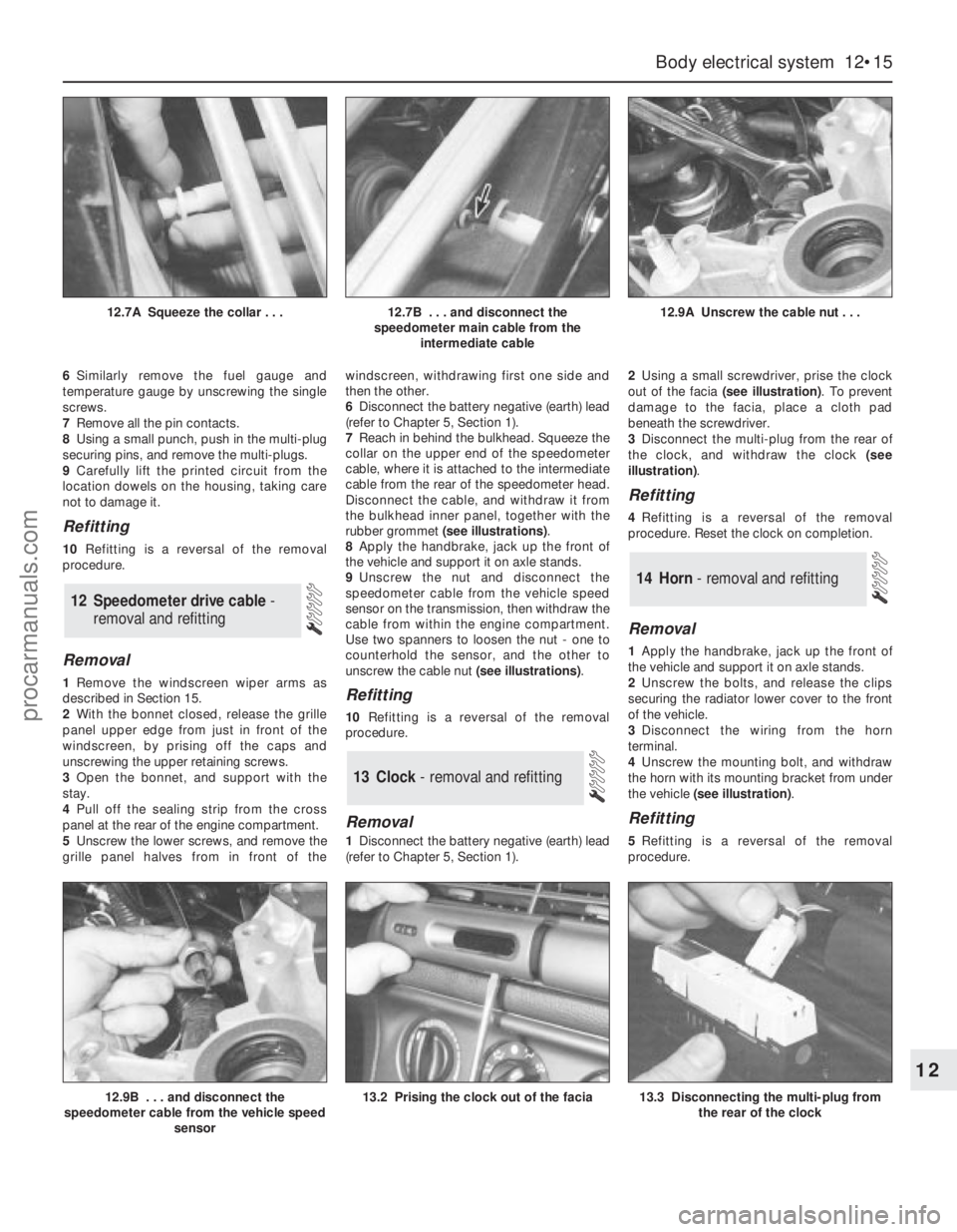
described in Section 15.
2With the bonnet closed, release the grille
panel upper edge from just in front of the
windscreen, by prising off the caps and
unscrewing the upper retaining screws.
3Open the bonnet, and support with the
stay.
4Pull off the sealing strip from the cross
panel at the rear of the engine compartment.
5Unscrew the lower screws, and remove the
grille panel halves from in front of thewindscreen, withdrawing first one side and
then the other.
6Disconnect the battery negative (earth) lead
(refer to Chapter 5, Section 1).
7Reach in behind the bulkhead. Squeeze the
collar on the upper end of the speedometer
cable, where it is attached to the intermediate
cable from the rear of the speedometer head.
Disconnect the cable, and withdraw it from
the bulkhead inner panel, together with the
rubber grommet (see illustrations).
8Apply the handbrake, jack up the front of
the vehicle and support it on axle stands.
9Unscrew the nut and disconnect the
speedometer cable from the vehicle speed
sensor on the transmission, then withdraw the
cable from within the engine compartment.
Use two spanners to loosen the nut - one to
counterhold the sensor, and the other to
unscrew the cable nut (see illustrations).Refitting
10Refitting is a reversal of the removal
procedure.
Removal
1Disconnect the battery negative (earth) lead
(refer to Chapter 5, Section 1).2Using a small screwdriver, prise the clock
out of the facia (see illustration). To prevent
damage to the facia, place a cloth pad
beneath the screwdriver.
3Disconnect the multi-plug from the rear of
the clock, and withdraw the clock (see
illustration).
Refitting
4Refitting is a reversal of the removal
procedure. Reset the clock on completion.
Removal
1Apply the handbrake, jack up the front of
the vehicle and support it on axle stands.
2Unscrew the bolts, and release the clips
securing the radiator lower cover to the front
of the vehicle.
3Disconnect the wiring from the horn
terminal.
4Unscrew the mounting bolt, and withdraw
the horn with its mounting bracket from under
the vehicle (see illustration).
Refitting
5Refitting is a reversal of the removal
procedure.
14 Horn - removal and refitting
13 Clock- removal and refitting
12 Speedometer drive cable -
removal and refitting
Body electrical system 12•15
12
12.9B . . . and disconnect the
speedometer cable from the vehicle speed
sensor13.2 Prising the clock out of the facia13.3 Disconnecting the multi-plug from
the rear of the clock
12.7A Squeeze the collar . . .12.7B . . . and disconnect the
speedometer main cable from the
intermediate cable12.9A Unscrew the cable nut . . .
procarmanuals.com
Page 219 of 279
the specified mileage (or time) since the last
service has been reached.
4To reset the service interval system and
turn off the light, a switch inside the glovebox
must be depressed for a minimum of 4
seconds with the ignition switched on. This
should be carried out by a Ford dealer if the
vehicle is still in the warranty period.
Component renewal
5The following paragraphs describe brief
removal procedures for the auxiliary warning
system components. Disconnect the battery
negative (earth) lead before commencing
work (refer to Chapter 5, Section 1). Refitting
procedures are a reversal of removal.
Display warning bulb
6Remove the control assembly.
7Prise off the cover, and pull out the relevant
bulb and bulbholder.
Low air temperature warning sender
unit
8Remove the front bumper.
9Unclip the sender unit and disconnect the
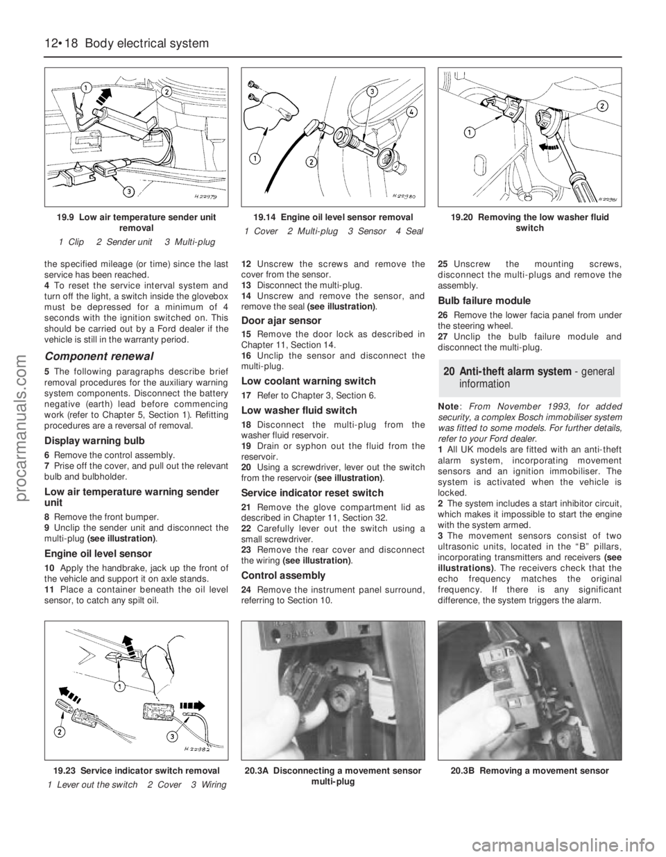
multi-plug (see illustration).
Engine oil level sensor
10Apply the handbrake, jack up the front of
the vehicle and support it on axle stands.
11Place a container beneath the oil level
sensor, to catch any spilt oil.12Unscrew the screws and remove the
cover from the sensor.
13Disconnect the multi-plug.
14Unscrew and remove the sensor, and
remove the seal (see illustration).
Door ajar sensor
15Remove the door lock as described in
Chapter 11, Section 14.
16Unclip the sensor and disconnect the
multi-plug.
Low coolant warning switch
17Refer to Chapter 3, Section 6.
Low washer fluid switch
18Disconnect the multi-plug from the
washer fluid reservoir.
19Drain or syphon out the fluid from the
reservoir.
20Using a screwdriver, lever out the switch
from the reservoir (see illustration).
Service indicator reset switch
21Remove the glove compartment lid as
described in Chapter 11, Section 32.
22Carefully lever out the switch using a
small screwdriver.
23Remove the rear cover and disconnect
the wiring (see illustration).
Control assembly
24Remove the instrument panel surround,
referring to Section 10.25Unscrew the mounting screws,
disconnect the multi-plugs and remove the
assembly.
Bulb failure module
26Remove the lower facia panel from under
the steering wheel.
27Unclip the bulb failure module and
disconnect the multi-plug.
Note: From November 1993, for added
security, a complex Bosch immobiliser system
was fitted to some models. For further details,
refer to your Ford dealer.
1All UK models are fitted with an anti-theft
alarm system, incorporating movement
sensors and an ignition immobiliser. The
system is activated when the vehicle is
locked.
2The system includes a start inhibitor circuit,
which makes it impossible to start the engine
with the system armed.
3The movement sensors consist of two
ultrasonic units, located in the “B” pillars,
incorporating transmitters and receivers (see
illustrations). The receivers check that the
echo frequency matches the original
frequency. If there is any significant
difference, the system triggers the alarm.
20 Anti-theft alarm system- general
information
12•18 Body electrical system
19.9 Low air temperature sender unit
removal
1 Clip 2 Sender unit 3 Multi-plug19.14 Engine oil level sensor removal
1 Cover 2 Multi-plug 3 Sensor 4 Seal19.20 Removing the low washer fluid
switch
19.23 Service indicator switch removal
1 Lever out the switch 2 Cover 3 Wiring20.3A Disconnecting a movement sensor
multi-plug20.3B Removing a movement sensor
procarmanuals.com
Page 220 of 279
4The system module is located on a bracket
beneath the right-hand side of the facia. The
set and reset switches are located in a
housing by the lock barrel holder in the doors,
tailgate or bootlid.
5To allow temporary opening of the tailgate
or bootlid, an inhibit switch is fitted to the lock
barrel. This suppresses the alarm system until
the tailgate or bootlid is closed again.
6Where remote central locking is fitted, an
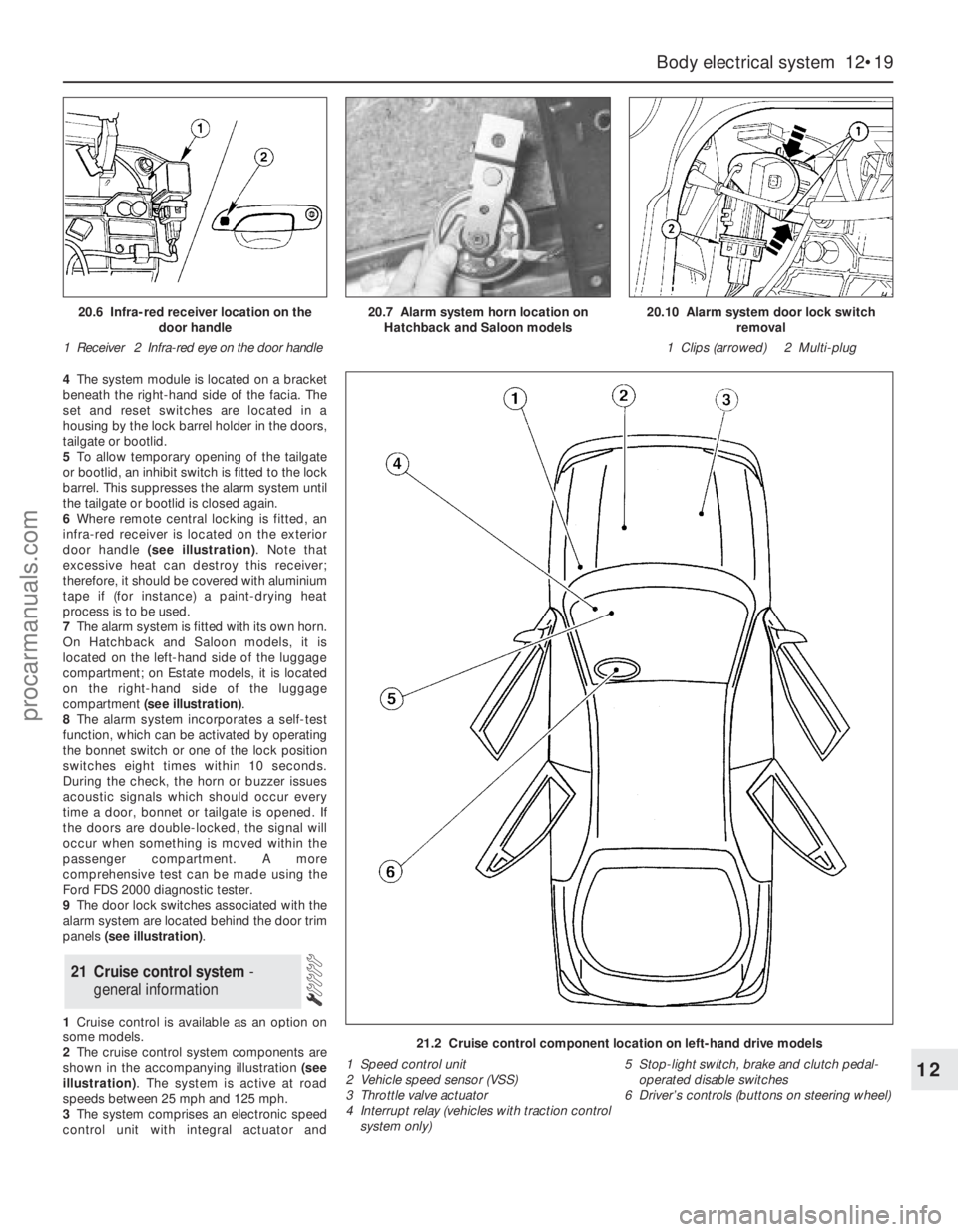
infra-red receiver is located on the exterior
door handle (see illustration). Note that
excessive heat can destroy this receiver;
therefore, it should be covered with aluminium
tape if (for instance) a paint-drying heat
process is to be used.
7The alarm system is fitted with its own horn.
On Hatchback and Saloon models, it is
located on the left-hand side of the luggage
compartment; on Estate models, it is located
on the right-hand side of the luggage
compartment (see illustration).
8The alarm system incorporates a self-test
function, which can be activated by operating
the bonnet switch or one of the lock position
switches eight times within 10 seconds.
During the check, the horn or buzzer issues
acoustic signals which should occur every
time a door, bonnet or tailgate is opened. If
the doors are double-locked, the signal will
occur when something is moved within the
passenger compartment. A more
comprehensive test can be made using the
Ford FDS 2000 diagnostic tester.
9The door lock switches associated with the
alarm system are located behind the door trim
panels (see illustration).
1Cruise control is available as an option on
some models.
2The cruise control system components are
shown in the accompanying illustration (see
illustration). The system is active at road
speeds between 25 mph and 125 mph.
3The system comprises an electronic speed
control unit with integral actuator and
21 Cruise control system -
general information
Body electrical system 12•19
12
21.2 Cruise control component location on left-hand drive models
1 Speed control unit
2 Vehicle speed sensor (VSS)
3 Throttle valve actuator
4 Interrupt relay (vehicles with traction control
system only)5 Stop-light switch, brake and clutch pedal-
operated disable switches
6 Driver’s controls (buttons on steering wheel)
20.6 Infra-red receiver location on the
door handle
1 Receiver 2 Infra-red eye on the door handle20.7 Alarm system horn location on
Hatchback and Saloon models20.10 Alarm system door lock switch
removal
1 Clips (arrowed) 2 Multi-plug
procarmanuals.com
Page 221 of 279
switches mounted in the engine compartment
with a control cable connected to the throttle
valve actuator, driver-operated switches,
brake and clutch pedal switches, an indicator
light, and a road speed sensor.
4The driver-operated switches are mounted
on the steering wheel, and allow the driver to
control the various functions.
5The vehicle speed sensor uses the
speedometer cable drive pinion to generate
pulses which are fed to the speed control unit.
6The stop-light switch, brake pedal switch
and (when applicable) clutch pedal switch are
used to disable the cruise control system. The
stop-light switch is activated when the brake
pedal is applied gently, and the brake pedal
switch is activated when the brake pedal is
applied forcibly.
7An indicator light on the instrument panel is
illuminated when the system is in operation.
8The following paragraphs describe brief
removal procedures for the cruise control
system components. The battery negative
(earth) lead should be disconnected before
commencing work (refer to Chapter 5, Sec-
tion 1). Refitting is a reversal of removal.
Speed control switch
9Remove the steering column upper and
lower shrouds, with reference to Chapter 10.
10Remove the air bag module as described
in Section 29.11Disconnect the multi-plugs, then unscrew
the screws and remove the switch.
Disable switches
12Remove the lower facia panel from under
the steering column.
13Disconnect the multi-plugs from the
clutch switch, brake pedal switch and stop-
light switch.
14To remove the clutch and brake pedal
switches, twist them anti-clockwise. To
remove the stop-light switch, twist it
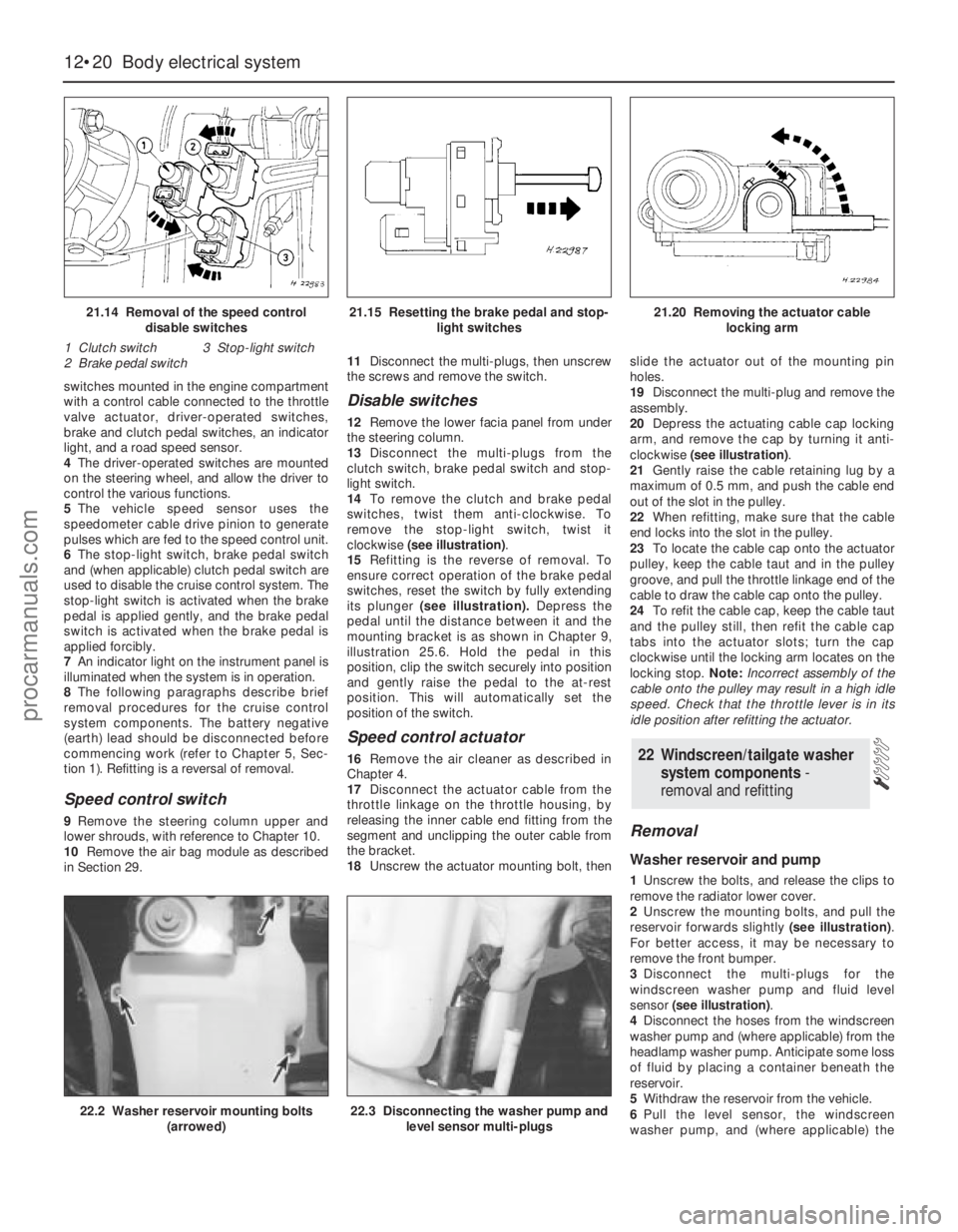
clockwise (see illustration).
15Refitting is the reverse of removal. To
ensure correct operation of the brake pedal
switches, reset the switch by fully extending
its plunger (see illustration).Depress the
pedal until the distance between it and the
mounting bracket is as shown in Chapter 9,
illustration 25.6. Hold the pedal in this
position, clip the switch securely into position
and gently raise the pedal to the at-rest
position. This will automatically set the
position of the switch.
Speed control actuator
16Remove the air cleaner as described in
Chapter 4.
17Disconnect the actuator cable from the
throttle linkage on the throttle housing, by
releasing the inner cable end fitting from the
segment and unclipping the outer cable from
the bracket.
18Unscrew the actuator mounting bolt, thenslide the actuator out of the mounting pin
holes.
19Disconnect the multi-plug and remove the
assembly.
20Depress the actuating cable cap locking
arm, and remove the cap by turning it anti-
clockwise (see illustration).
21Gently raise the cable retaining lug by a
maximum of 0.5 mm, and push the cable end
out of the slot in the pulley.
22When refitting, make sure that the cable
end locks into the slot in the pulley.
23To locate the cable cap onto the actuator
pulley, keep the cable taut and in the pulley
groove, and pull the throttle linkage end of the
cable to draw the cable cap onto the pulley.
24To refit the cable cap, keep the cable taut
and the pulley still, then refit the cable cap
tabs into the actuator slots; turn the cap
clockwise until the locking arm locates on the
locking stop. Note:Incorrect assembly of the
cable onto the pulley may result in a high idle
speed. Check that the throttle lever is in its
idle position after refitting the actuator.
Removal
Washer reservoir and pump
1Unscrew the bolts, and release the clips to
remove the radiator lower cover.
2Unscrew the mounting bolts, and pull the
reservoir forwards slightly (see illustration).
For better access, it may be necessary to
remove the front bumper.
3Disconnect the multi-plugs for the
windscreen washer pump and fluid level
sensor (see illustration).
4Disconnect the hoses from the windscreen
washer pump and (where applicable) from the
headlamp washer pump. Anticipate some loss
of fluid by placing a container beneath the
reservoir.
5Withdraw the reservoir from the vehicle.
6Pull the level sensor, the windscreen
washer pump, and (where applicable) the
22 Windscreen/tailgate washer
system components -
removal and refitting
12•20 Body electrical system
21.14 Removal of the speed control
disable switches
1 Clutch switch 3 Stop-light switch
2 Brake pedal switch21.15 Resetting the brake pedal and stop-
light switches21.20 Removing the actuator cable
locking arm
22.2 Washer reservoir mounting bolts
(arrowed)22.3 Disconnecting the washer pump and
level sensor multi-plugs
procarmanuals.com