1993 FORD MONDEO brake sensor
[x] Cancel search: brake sensorPage 142 of 279
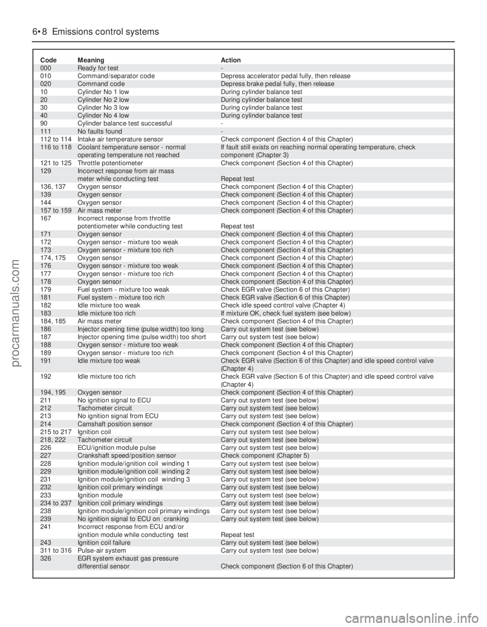
6•8 Emissions control systems
Code Meaning Action
000 Ready for test -
010 Command/separator code Depress accelerator pedal fully, then release
020 Command code Depress brake pedal fully, then release
10 Cylinder No 1 low During cylinder balance test
20 Cylinder No 2 low During cylinder balance test
30 Cylinder No 3 low During cylinder balance test
40 Cylinder No 4 low During cylinder balance test
90 Cylinder balance test successful -
111 No faults found -
112 to 114 Intake air temperature sensor Check component (Section 4 of this Chapter)116 to 118 Coolant temperature sensor - normal If fault still exists on reaching normal operating temperature, check
operating temperature not reached component (Chapter 3)
121 to 125 Throttle potentiometer Check component (Section 4 of this Chapter)129 Incorrect response from air mass
meter while conducting test Repeat test
136, 137 Oxygen sensor Check component (Section 4 of this Chapter)
139 Oxygen sensor Check component (Section 4 of this Chapter)
144 Oxygen sensor Check component (Section 4 of this Chapter)
157 to 159 Air mass meter Check component (Section 4 of this Chapter)
167 Incorrect response from throttle
potentiometer while conducting test Repeat test
171 Oxygen sensor Check component (Section 4 of this Chapter)
172 Oxygen sensor - mixture too weak Check component (Section 4 of this Chapter)
173 Oxygen sensor - mixture too rich Check component (Section 4 of this Chapter)
174, 175 Oxygen sensor Check component (Section 4 of this Chapter)
176 Oxygen sensor - mixture too weak Check component (Section 4 of this Chapter)
177 Oxygen sensor - mixture too rich Check component (Section 4 of this Chapter)
178 Oxygen sensor Check component (Section 4 of this Chapter)
179 Fuel system - mixture too weak Check EGR valve (Section 6 of this Chapter)
181 Fuel system - mixture too rich Check EGR valve (Section 6 of this Chapter)
182 Idle mixture too weak Check idle speed control valve (Chapter 4)
183 Idle mixture too rich If mixture OK, check fuel system (see below)
184, 185 Air mass meter Check component (Section 4 of this Chapter)
186 Injector opening time (pulse width) too long Carry out system test (see below)
187 Injector opening time (pulse width) too short Carry out system test (see below)
188 Oxygen sensor - mixture too weak Check component (Section 4 of this Chapter)
189 Oxygen sensor - mixture too rich Check component (Section 4 of this Chapter)191 Idle mixture too weak Check EGR valve (Section 6 of this Chapter) and idle speed control valve
(Chapter 4)
192 Idle mixture too rich Check EGR valve (Section 6 of this Chapter) and idle speed control valve
(Chapter 4)
194, 195 Oxygen sensor Check component (Section 4 of this Chapter)
211 No ignition signal to ECU Carry out system test (see below)
212 Tachometer circuit Carry out system test (see below)
213 No ignition signal from ECU Carry out system test (see below)
214 Camshaft position sensor Check component (Section 4 of this Chapter)
215 to 217 Ignition coil Carry out system test (see below)
218, 222 Tachometer circuit Carry out system test (see below)
226 ECU/ignition module pulse Carry out system test (see below)
227 Crankshaft speed/position sensor Check component (Chapter 5)
228 Ignition module/ignition coil winding 1 Carry out system test (see below)
229 Ignition module/ignition coil winding 2 Carry out system test (see below)
231 Ignition module/ignition coil winding 3 Carry out system test (see below)
232 Ignition coil primary windings Carry out system test (see below)
233 Ignition module Carry out system test (see below)
234 to 237 Ignition coil primary windings Carry out system test (see below)
238 Ignition module/ignition coil primary windings Carry out system test (see below)
239 No ignition signal to ECU on cranking Carry out system test (see below)
241 Incorrect response from ECU and/or
ignition module while conducting test Repeat test
243 Ignition coil failure Carry out system test (see below)
311 to 316 Pulse-air system Carry out system test (see below)326 EGR system exhaust gas pressure
differential sensor Check component (Section 6 of this Chapter)
procarmanuals.com
Page 143 of 279
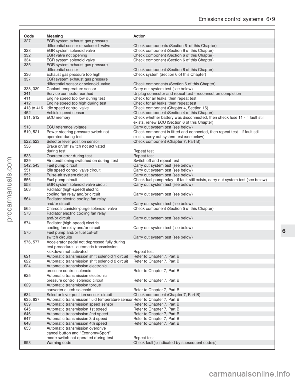
Code Meaning Action327 EGR system exhaust gas pressure
differential sensor or solenoid valve Check components (Section 6 of this Chapter)
328 EGR system solenoid valve Check component (Section 6 of this Chapter)
332 EGR valve not opening Check component (Section 6 of this Chapter)
334 EGR system solenoid valve Check component (Section 6 of this Chapter)335 EGR system exhaust gas pressure
differential sensor Check component (Section 6 of this Chapter)
336 Exhaust gas pressure too high Check system (Section 6 of this Chapter)337 EGR system exhaust gas pressure
differential sensor or solenoid valve Check components (Section 6 of this Chapter)
338, 339 Coolant temperature sensor Carry out system test (see below)
341 Service connector earthed Unplug connector and repeat test - reconnect on completion
411 Engine speed too low during test Check for air leaks, then repeat test
412 Engine speed too high during test Check for air leaks, then repeat test
413 to 416 Idle speed control valve Check component (Chapter 4, Section 16)
452 Vehicle speed sensor Check component (Section 4 of this Chapter)
511, 512 ECU memory Check whether battery was disconnected, then check fuse 11 - if fault still
exists, renew ECU (Section 6 of this Chapter)
513 ECU reference voltage Carry out system test (see below)
519, 521 Power steering pressure switch not Check component is fitted and connected, then repeat test - if fault still
operated during test exists, carry out system test (see below)
522, 523 Selector lever position sensor Check component (Chapter 7, Part B)
536 Brake on/off switch not activated
during test Repeat test
538 Operator error during test Repeat test
539 Air conditioning switched on during test Switch off and repeat test
542, 543 Fuel pump circuit Carry out system test (see below)
551 Idle speed control valve circuit Carry out system test (see below)
552 Pulse-air system circuit Carry out system test (see below)
556 Fuel pump circuit Check fuel pump relay - if fault still exists, carry out system test (see below)
558 EGR system solenoid valve circuit Carry out system test (see below)
563 Radiator (high-speed) electric
cooling fan relay and/or circuit Carry out system test (see below)564 Radiator electric cooling fan relay
and/or circuit Carry out system test (see below)
565 Charcoal canister-purge solenoid valve Check component (Section 5 of this Chapter)573 Radiator electric cooling fan relay
and/or circuit Carry out system test (see below)
574 Radiator (high-speed) electric
cooling fan relay and/or circuit Carry out system test (see below)575 Fuel pump and/or fuel cut-off
switch circuits Carry out system test (see below)
576, 577 Accelerator pedal not depressed fully during
test procedure - automatic transmission
kickdown not activated Repeat test
621 Automatic transmission shift solenoid 1 circuit Refer to Chapter 7, Part B
622 Automatic transmission shift solenoid 2 circuit Refer to Chapter 7, Part B
624 Automatic transmission electronic
pressure control solenoid Refer to Chapter 7, Part B
625 Automatic transmission electronic
pressure control solenoid circuit Refer to Chapter 7, Part B
629 Automatic transmission torque
converter clutch solenoid Refer to Chapter 7, Part B
634 Selector lever position sensor circuit Check component (Chapter 7, Part B)
635, 637 Automatic transmission fluid temperature sensor Refer to Chapter 7, Part B
639 Automatic transmission speed sensor Refer to Chapter 7, Part B
645 Automatic transmission 1st speed Refer to Chapter 7, Part B
646 Automatic transmission 2nd speed Refer to Chapter 7, Part B
647 Automatic transmission 3rd speed Refer to Chapter 7, Part B
648 Automatic transmission 4th speed Refer to Chapter 7, Part B
653 Automatic transmission overdrive
cancel button and “Economy/Sport”
mode switch not operated during test Repeat test
998 Warning code Check fault(s) indicated by subsequent code(s)
Emissions control systems 6•9
6
procarmanuals.com
Page 144 of 279
Ignition timing and base idle
speed check
Note:The following procedure is a check only,
essentially of the ECU. Both the ignition timing
and the base idle speed are controlled by the
ECU. The ignition timing is not adjustable at
all; the base idle speed is set in production,
and should not be altered.
38If the fault code read-out (with any checks
resulting from it) has not eliminated the fault,
the next step is to check the ECU’s control of
the ignition timing and the base idle speed.
This task requires the use of a Ford STAR
tester (a proprietary fault code reader can be
used only if it is capable of inducing the ECU
to enter its “Service Adjustment Programme”),
coupled with an accurate tachometer and a
good-quality timing light. Without this
equipment, the task is not possible; the
vehicle must be taken to a Ford dealer for
attention.
39To make the check, apply the handbrake,
switch off the air conditioning (where fitted)
and any other electrical loads (lights, heated
rear window, etc), then select neutral (manual
transmission) or the “P” position (automatic
transmission). Start the engine, and warm it
up to normal operating temperature. The
radiator electric cooling fan must be running
continuously while the check is made; this
should be activated by the ECU, when
prompted by the tester. Switch off the engine,
and connect the test equipment as directed
by the manufacturer - refer to paragraph 26
above for details of STAR tester connection.
40Raise and support the front of the vehicle
securely, and remove the auxiliary drivebelt
cover (see Chapter 1). Emphasise the two
pairs of notches in the inner and outer rims of
the crankshaft pulley, using white paint. Note
that an ignition timing reference mark is not
provided on the pulley - in the normal
direction of crankshaft rotation (clockwise,
seen from the right-hand side of the vehicle)
the first pair of notches are irrelevant to the
vehicles covered in this manual, while the
second pair indicate Top Dead Centre (TDC)
when aligned with the rear edge of the raised
mark on the sump; when checking the ignition
timing, therefore, the (rear edge of the) sumpmark should appear just before the TDC
notches (see Part A of Chapter 2, Section 4,
for further information if required).
41Start the engine and allow it to idle. Work
through the engine-running test procedure
until the ECU enters its “Service Adjustment
Programme” - see paragraph 35 above.
42Use the timing light to check that the
timing marks appear approximately as
outlined above at idle speed. Do not spend
too much time on this check; if the timing
appears to be incorrect, the system may have
a fault, and a full system test must be carried
out (see below) to establish its cause.
43Using the tachometer, check that the
base idle speed is as given in the
Specifications Section of Chapter 4.
44If the recorded speed differs significantly
from the specified value, check for air leaks,
as described in the preliminary checks
(paragraphs 15 to 18 above), or any other
faults which might cause the discrepancy.
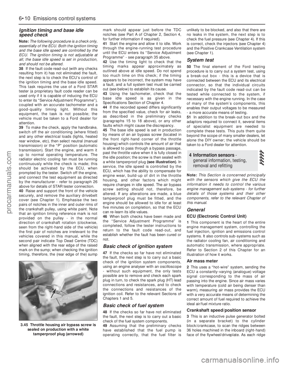
45The base idle speed is set in production
by means of an air bypass screw (located in
the front right-hand corner of the throttle
housing) which controls the amount of air that
is allowed to pass through a bypass passage,
past the throttle valve when it is fully closed in
the idle position; the screw is then sealed with
a white tamperproof plug (see illustration). In
service, the idle speed is controlled by the
ECU, which has the ability to compensate for
engine wear, build-up of dirt in the throttle
housing, and other factors which might
require changes in idle speed. The air bypass
screw setting should not, therefore, be
altered. If any alterations are made, a blue
tamperproof plug must be fitted, and the
engine should be allowed to idle for at least
five minutes on completion, so that the ECU
can re-learn its idle values.
46When both checks have been made and
the “Service Adjustment Programme” is
completed, follow the tester instructions to
return to the fault code read-out, and
establish whether the fault has been cured or
not.
Basic check of ignition system
47If the checks so far have not eliminated
the fault, the next step is to carry out a basic
check of the ignition system components,
using an engine analyser with an oscilloscope
- without such equipment, the only tests
possible are to remove and check each spark
plug in turn, to check the spark plug (HT) lead
connections and resistances, and to check
the connections and resistances of the
ignition coil. Refer to the relevant Sections of
Chapters 1 and 5.
Basic check of fuel system
48If the checks so far have not eliminated
the fault, the next step is to carry out a basic
check of the fuel system components.
49Assuming that the preliminary checks
have established that the fuel pump is
operating correctly, that the fuel filter isunlikely to be blocked, and also that there are
no leaks in the system, the next step is to
check the fuel pressure (see Chapter 4). If this
is correct, check the injectors (see Chapter 4)
and the Positive Crankcase Ventilation system
(see Chapter 1).
System test
50The final element of the Ford testing
procedure is to carry out a system test, using
a break-out box - this is a device that is
connected between the ECU and its electrical
connector, so that the individual circuits
indicated by the fault code read-out can be
tested while connected to the system, if
necessary with the engine running. In the case
of many of the system’s components, this
enables their output voltages to be measured
- a more accurate means of testing.
51In addition to the break-out box and the
adaptors required to connect it, several items
of specialist equipment are needed to
complete these tests. This puts them quite
beyond the scope of many smaller dealers, let
alone the DIY owner; the vehicle should be
taken to a Ford dealer for attention.
Note:This Section is concerned principally
with the sensors which give the ECU the
information it needs to control the various
engine management sub-systems - for further
details of those systems and their other
components, refer to the relevant Chapter of
this manual.
General
ECU (Electronic Control Unit)
1This component is the heart of the entire
engine management system, controlling the
fuel injection, ignition and emissions control
systems. It also controls sub-systems such as
the radiator cooling fan, air conditioning and
automatic transmission, where appropriate.
Refer to Section 2 of this Chapter for an
illustration of how it works.
Air mass meter
2This uses a “hot-wire” system, sending the
ECU a constantly-varying (analogue) voltage
signal corresponding to the mass of air
passing into the engine. Since air mass varies
with temperature (cold air being denser than
warm), measuring air mass provides the ECU
with a very accurate means of determining the
correct amount of fuel required to achieve the
ideal air/fuel mixture ratio.
Crankshaft speed/position sensor
3This is an inductive pulse generator bolted
(in a separate bracket) to the cylinder
block/crankcase, to scan the ridges between
36 holes machined in the inboard (right-hand)
face of the flywheel/driveplate. As each ridge
4 Information sensors -
general information, testing,
removal and refitting
6•10 Emissions control systems
3.45 Throttle housing air bypass screw is
sealed on production with a white
tamperproof plug (arrowed)
procarmanuals.com
Page 157 of 279
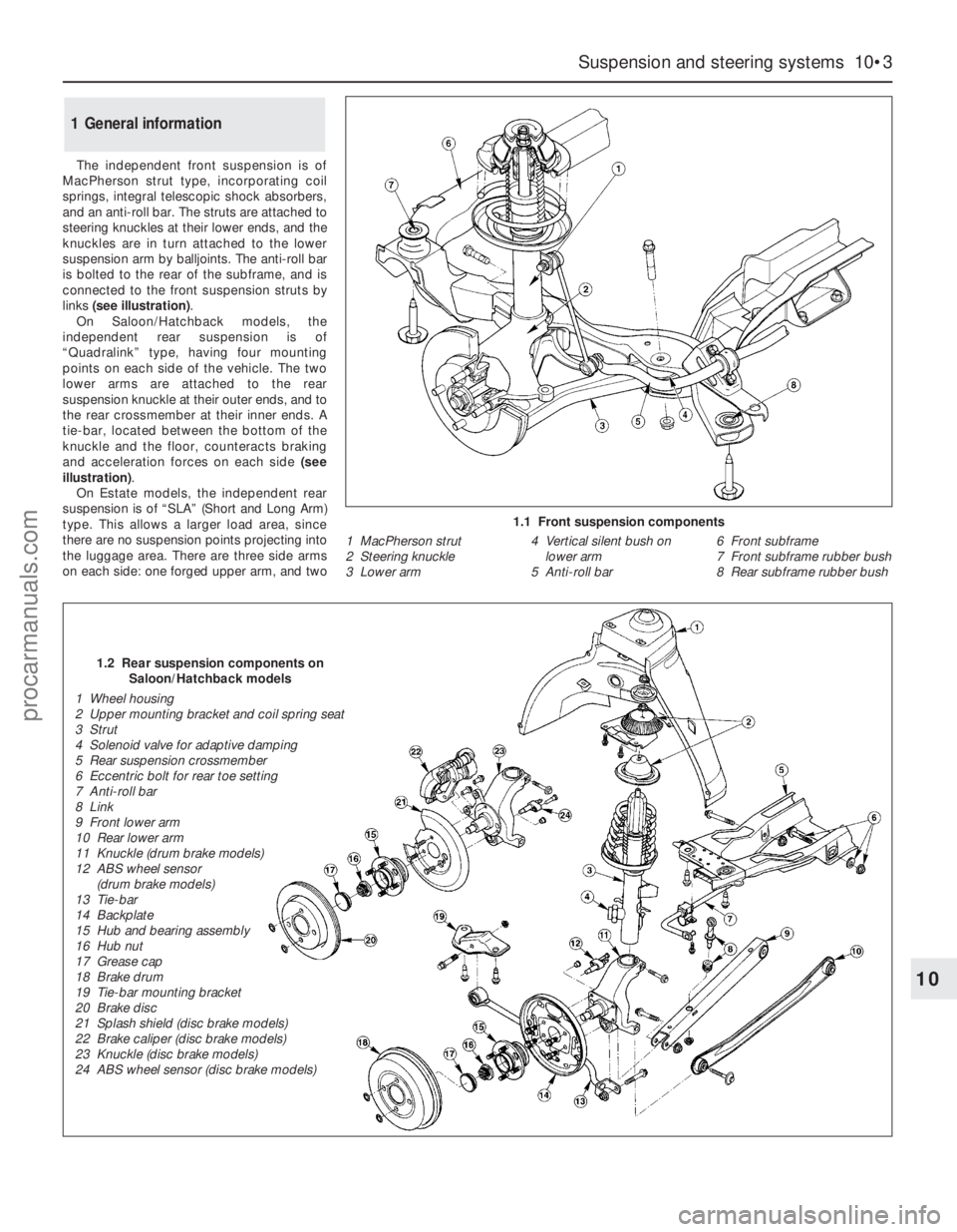
The independent front suspension is of
MacPherson strut type, incorporating coil
springs, integral telescopic shock absorbers,
and an anti-roll bar. The struts are attached to
steering knuckles at their lower ends, and the
knuckles are in turn attached to the lower
suspension arm by balljoints. The anti-roll bar
is bolted to the rear of the subframe, and is
connected to the front suspension struts by
links (see illustration).
On Saloon/Hatchback models, the
independent rear suspension is of
“Quadralink” type, having four mounting
points on each side of the vehicle. The two
lower arms are attached to the rear
suspension knuckle at their outer ends, and to
the rear crossmember at their inner ends. A
tie-bar, located between the bottom of the
knuckle and the floor, counteracts braking
and acceleration forces on each side (see
illustration).
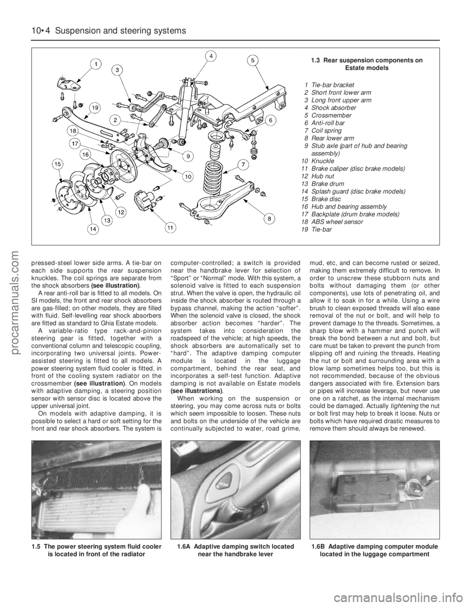
On Estate models, the independent rear
suspension is of “SLA” (Short and Long Arm)
type. This allows a larger load area, since
there are no suspension points projecting into
the luggage area. There are three side arms
on each side: one forged upper arm, and two
1 General information
Suspension and steering systems 10•3
10
1.1 Front suspension components
1 MacPherson strut
2 Steering knuckle
3 Lower arm4 Vertical silent bush on
lower arm
5 Anti-roll bar6 Front subframe
7 Front subframe rubber bush
8 Rear subframe rubber bush
1.2 Rear suspension components on
Saloon/Hatchback models
1 Wheel housing
2 Upper mounting bracket and coil spring seat
3 Strut
4 Solenoid valve for adaptive damping
5 Rear suspension crossmember
6 Eccentric bolt for rear toe setting
7 Anti-roll bar
8 Link
9 Front lower arm
10 Rear lower arm
11 Knuckle (drum brake models)
12 ABS wheel sensor
(drum brake models)
13 Tie-bar
14 Backplate
15 Hub and bearing assembly
16 Hub nut
17 Grease cap
18 Brake drum
19 Tie-bar mounting bracket
20 Brake disc
21 Splash shield (disc brake models)
22 Brake caliper (disc brake models)
23 Knuckle (disc brake models)
24 ABS wheel sensor (disc brake models)
procarmanuals.com
Page 158 of 279
10•4 Suspension and steering systems
pressed-steel lower side arms. A tie-bar on
each side supports the rear suspension
knuckles. The coil springs are separate from
the shock absorbers (see illustration).
A rear anti-roll bar is fitted to all models. On
SI models, the front and rear shock absorbers
are gas-filled; on other models, they are filled
with fluid. Self-levelling rear shock absorbers
are fitted as standard to Ghia Estate models.
A variable-ratio type rack-and-pinion
steering gear is fitted, together with a
conventional column and telescopic coupling,
incorporating two universal joints. Power-
assisted steering is fitted to all models. A
power steering system fluid cooler is fitted, in
front of the cooling system radiator on the
crossmember (see illustration). On models
with adaptive damping, a steering position
sensor with sensor disc is located above the
upper universal joint.
On models with adaptive damping, it is
possible to select a hard or soft setting for the
front and rear shock absorbers. The system iscomputer-controlled; a switch is provided
near the handbrake lever for selection of
“Sport” or “Normal” mode. With this system, a
solenoid valve is fitted to each suspension
strut. When the valve is open, the hydraulic oil
inside the shock absorber is routed through a
bypass channel, making the action “softer”.
When the solenoid valve is closed, the shock
absorber action becomes “harder”. The
system takes into consideration the
roadspeed of the vehicle; at high speeds, the
shock absorbers are automatically set to
“hard”. The adaptive damping computer
module is located in the luggage
compartment, behind the rear seat, and
incorporates a self-test function. Adaptive
damping is not available on Estate models
(see illustrations).
When working on the suspension or
steering, you may come across nuts or bolts
which seem impossible to loosen. These nuts
and bolts on the underside of the vehicle are
continually subjected to water, road grime,mud, etc, and can become rusted or seized,
making them extremely difficult to remove. In
order to unscrew these stubborn nuts and
bolts without damaging them (or other
components), use lots of penetrating oil, and
allow it to soak in for a while. Using a wire
brush to clean exposed threads will also ease
removal of the nut or bolt, and will help to
prevent damage to the threads. Sometimes, a
sharp blow with a hammer and punch will
break the bond between a nut and bolt, but
care must be taken to prevent the punch from
slipping off and ruining the threads. Heating
the nut or bolt and surrounding area with a
blow lamp sometimes helps too, but this is
not recommended, because of the obvious
dangers associated with fire. Extension bars
or pipes will increase leverage, but never use
one on a ratchet, as the internal mechanism
could be damaged. Actually tighteningthe nut
or bolt first may help to break it loose. Nuts or
bolts which have required drastic measures to
remove them should always be renewed.
1.5 The power steering system fluid cooler
is located in front of the radiator
1.6A Adaptive damping switch located
near the handbrake lever1.6B Adaptive damping computer module
located in the luggage compartment
1.3 Rear suspension components on
Estate models
1 Tie-bar bracket
2 Short front lower arm
3 Long front upper arm
4 Shock absorber
5 Crossmember
6 Anti-roll bar
7 Coil spring
8 Rear lower arm
9 Stub axle (part of hub and bearing
assembly)
10 Knuckle
11 Brake caliper (disc brake models)
12 Hub nut
13 Brake drum
14 Splash guard (disc brake models)
15 Brake disc
16 Hub and bearing assembly
17 Backplate (drum brake models)
18 ABS wheel sensor
19 Tie-bar
procarmanuals.com
Page 159 of 279
Since most of the procedures dealt with in
this Chapter involve jacking up the vehicle
and working underneath it, a good pair of axle
stands will be needed. A hydraulic trolley jack
is the preferred type of jack to lift the vehicle,
and it can also be used to support certain
components during removal and refitting
operations.
Warning: Never, under any
circumstances, rely on a jack to
support the vehicle while working
beneath it. When jacking up the vehicle, do
not lift or support it beneath the front or
rear subframes.
Removal
1Apply the handbrake. Remove the wheel
cover from the relevant front wheel, and
loosen (but do not remove) the driveshaft/hub
nut. This nut is very tight.
2Loosen the front wheel nuts, jack up the
front of the vehicle and support it on axle
stands. Remove the front wheel.
3Extract the split pin from the track rod end
balljoint nut. Unscrew the nut, and detach the
rod from the arm on the steering knuckle
using a conventional balljoint removal tool.
Take care not to damage the balljoint seal.
4Remove the ABS sensor (when fitted) as
described in Chapter 9.
5Remove the brake caliper and brake disc as
described in Chapter 9, but do not disconnect
the flexible hose from the caliper. Suspend
the caliper from a suitable point under the
wheel arch, taking care not to strain the hose.
6Unscrew and remove the driveshaft/hub
nut. Note that the nut is of special laminated
design, and should only be re-used a
maximum of 5 times. (It is a good idea to file a
small notch on the nut every time it is
removed.) Obtain a new nut if necessary.
7Note which way round the lower arm
balljoint clamp bolt is fitted, then unscrew and
remove it from the knuckle assembly. Lever
the balljoint down from the knuckle; if it is
tight, prise the clamp open using a large flat-
bladed tool. Take care not to damage the
balljoint seal during the separation procedure.
8Unscrew and remove the pinch-bolt
securing the steering knuckle assembly to the
front suspension strut, noting which way
round it is fitted. Prise open the clamp using a
wedge-shaped tool, and release the knuckle
from the strut. If necessary, tap the knuckle
downwards with a soft-headed mallet to
separate the two components. Support the
knuckle on an axle stand.
9Pull the steering knuckle and hub assembly
from the driveshaft splines. If it is tight,
connect a universal puller to the hub flange,
and withdraw it from the driveshaft. When the
driveshaft is free, support it on an axle stand,
or suspend it from a suitable point under thewheel arch, making sure that the inner
constant velocity joint is not turned through
more than 18°. (Damage may occur if the joint
is turned through too great an angle.)
Refitting
10Lift the steering knuckle and hub
assembly onto the driveshaft splines, and
support the assembly on an axle stand.
11Locate the assembly on the front
suspension strut. Insert the pinch-bolt with its
head facing forwards. Fit the nut and tighten it
to the specified torque.
12Refit the lower arm balljoint to the knuckle
assembly, and insert the clamp bolt with its
head facing forwards. Refit the nut and tighten
it to the specified torque.
13Refit the driveshaft/hub nut, and tighten it
moderately at this stage. Final tightening of
the nut is made with the vehicle lowered to the
ground.
14Refit the brake caliper and brake disc as
described in Chapter 9.
15Where fitted, refit the ABS sensor as
described in Chapter 9.
16Reconnect the track rod end balljoint to
the steering arm, and tighten the nut to the
specified torque. Check that the split pin
holes are aligned; if necessary, turn the nut to
the nearest alignment, making sure that the
torque wrench setting is still within the
specified range. Insert a new split pin, and
bend it back to secure.
17Refit the front wheel, and lower the
vehicle to the ground. Tighten the wheel nuts
to the specified torque.
18Tighten the driveshaft/hub nut to the
specified torque, and refit the wheel cover.
Inspection
1The front hub bearings are non-adjustable,
and are supplied already greased.
2To check the bearings for excessive wear,
apply the handbrake, jack up the front of the
vehicle and support it on axle stands.
3Grip the front wheel at top and bottom, and
attempt to rock it. If excessive movement is
noted, it may be that the hub bearings are
worn. Do not confuse wear in the driveshaft
outer joint or front suspension lower arm
balljoint with wear in the bearings. Hub
bearing wear will show up as roughness or
vibration when the wheel is spun; it will also
be noticeable as a rumbling or growling noise
when driving.
Renewal
4Remove the steering knuckle and hub
assembly as described in Section 2.
5The hub must now be removed from the
bearing inner races. It is preferable to use a
press to do this, but it is possible to drive outthe hub using a length of metal tube of
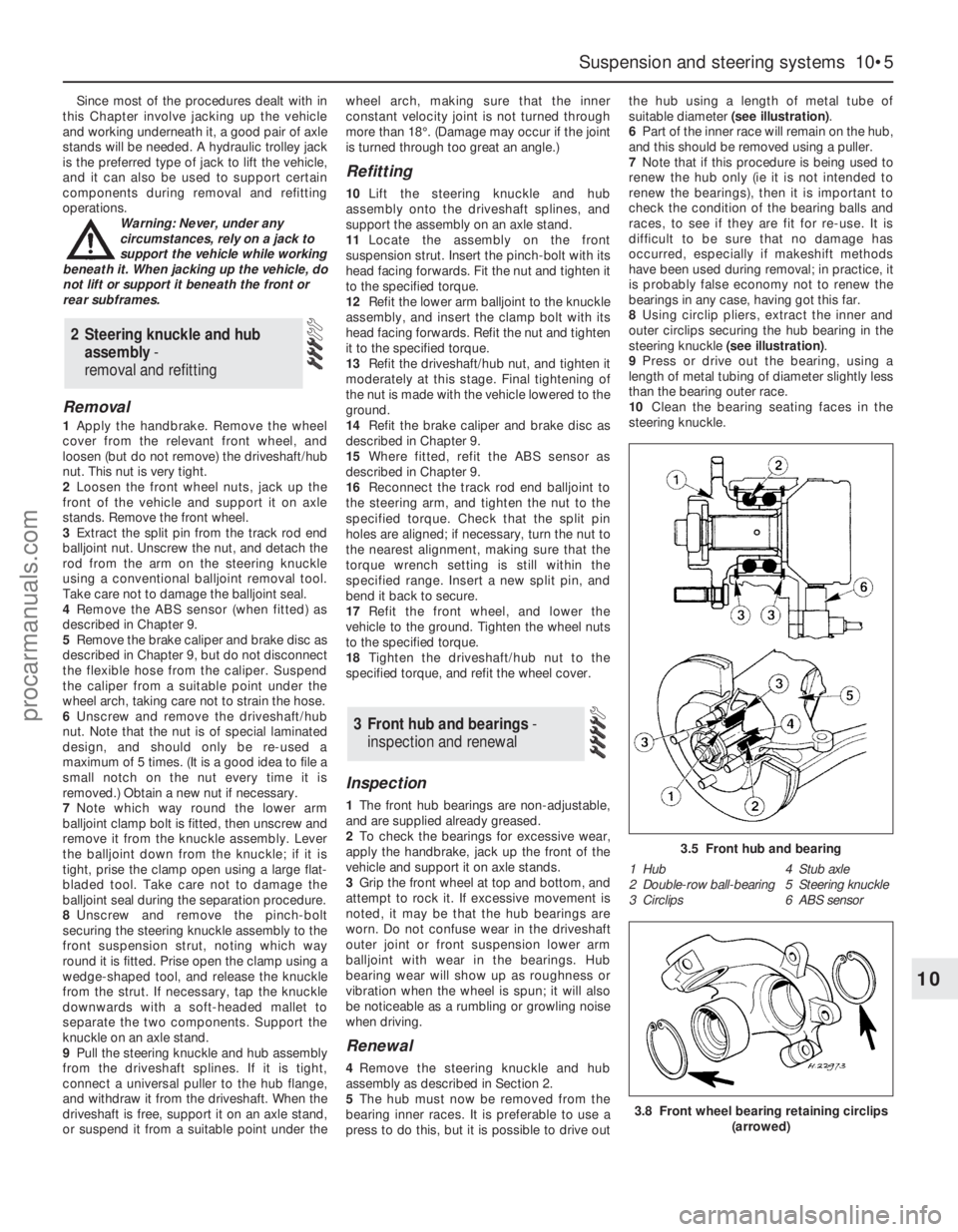
suitable diameter (see illustration).
6Part of the inner race will remain on the hub,
and this should be removed using a puller.
7Note that if this procedure is being used to
renew the hub only (ie it is not intended to
renew the bearings), then it is important to
check the condition of the bearing balls and
races, to see if they are fit for re-use. It is
difficult to be sure that no damage has
occurred, especially if makeshift methods
have been used during removal; in practice, it
is probably false economy not to renew the
bearings in any case, having got this far.
8Using circlip pliers, extract the inner and
outer circlips securing the hub bearing in the
steering knuckle (see illustration).
9Press or drive out the bearing, using a
length of metal tubing of diameter slightly less
than the bearing outer race.
10Clean the bearing seating faces in the
steering knuckle.
3 Front hub and bearings -
inspection and renewal
2 Steering knuckle and hub
assembly -
removal and refitting
Suspension and steering systems 10•5
10
3.5 Front hub and bearing
1 Hub 4 Stub axle
2 Double-row ball-bearing 5 Steering knuckle
3 Circlips 6 ABS sensor
3.8 Front wheel bearing retaining circlips
(arrowed)
procarmanuals.com
Page 160 of 279
11Locate one of the circlips in the outer
groove of the knuckle.
12Press or drive the new bearing into the
knuckle until it contacts the circlip, using a
length of metal tube of diameter slightly less
than the outer race. Do not apply any
pressure to the inner race.
13Locate the remaining circlip in the inner
groove of the knuckle.
14Support the inner race on a length of
metal tube, then press or drive the hub fully
into the bearing.
15Refit the steering knuckle and hub
assembly as described in Section 2.
Removal
1Apply the handbrake, then jack up the front
of the vehicle and support it on axle stands.
Remove the appropriate front wheel.
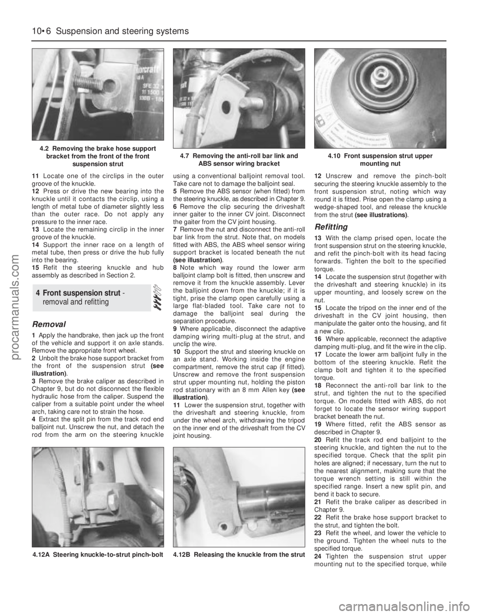
2Unbolt the brake hose support bracket from
the front of the suspension strut (see
illustration).
3Remove the brake caliper as described in
Chapter 9, but do not disconnect the flexible
hydraulic hose from the caliper. Suspend the
caliper from a suitable point under the wheel
arch, taking care not to strain the hose.
4Extract the split pin from the track rod end
balljoint nut. Unscrew the nut, and detach the
rod from the arm on the steering knuckleusing a conventional balljoint removal tool.
Take care not to damage the balljoint seal.
5Remove the ABS sensor (when fitted) from
the steering knuckle, as described in Chapter 9.
6Remove the clip securing the driveshaft
inner gaiter to the inner CV joint. Disconnect
the gaiter from the CV joint housing.
7Remove the nut and disconnect the anti-roll
bar link from the strut. Note that, on models
fitted with ABS, the ABS wheel sensor wiring
support bracket is located beneath the nut
(see illustration).
8Note which way round the lower arm
balljoint clamp bolt is fitted, then unscrew and
remove it from the knuckle assembly. Lever
the balljoint down from the knuckle; if it is
tight, prise the clamp open carefully using a
large flat-bladed tool. Take care not to
damage the balljoint seal during the
separation procedure.
9Where applicable, disconnect the adaptive
damping wiring multi-plug at the strut, and
unclip the wire.
10Support the strut and steering knuckle on
an axle stand. Working inside the engine
compartment, remove the strut cap (if fitted).
Unscrew and remove the front suspension
strut upper mounting nut, holding the piston
rod stationary with an 8 mm Allen key (see
illustration).
11Lower the suspension strut, together with
the driveshaft and steering knuckle, from
under the wheel arch, withdrawing the tripod
on the inner end of the driveshaft from the CV
joint housing.12Unscrew and remove the pinch-bolt
securing the steering knuckle assembly to the
front suspension strut, noting which way
round it is fitted. Prise open the clamp using a
wedge-shaped tool, and release the knuckle
from the strut (see illustrations).
Refitting
13With the clamp prised open, locate the
front suspension strut on the steering knuckle,
and refit the pinch-bolt with its head facing
forwards. Tighten the bolt to the specified
torque.
14Locate the suspension strut (together with
the driveshaft and steering knuckle) in its
upper mounting, and loosely screw on the
nut.
15Locate the tripod on the inner end of the
driveshaft in the CV joint housing, then
manipulate the gaiter onto the housing, and fit
a new clip.
16Where applicable, reconnect the adaptive
damping multi-plug, and fit the wire in the clip.
17Locate the lower arm balljoint fully in the
bottom of the steering knuckle. Refit the
clamp bolt and tighten it to the specified
torque.
18Reconnect the anti-roll bar link to the
strut, and tighten the nut to the specified
torque. On models fitted with ABS, do not
forget to locate the sensor wiring support
bracket beneath the nut.
19Where fitted, refit the ABS sensor as
described in Chapter 9.
20Refit the track rod end balljoint to the
steering knuckle, and tighten the nut to the
specified torque. Check that the split pin
holes are aligned; if necessary, turn the nut to
the nearest alignment, making sure that the
torque wrench setting is still within the
specified range. Insert a new split pin, and
bend it back to secure.
21Refit the brake caliper as described in
Chapter 9.
22Refit the brake hose support bracket to
the strut, and tighten the bolt.
23Refit the wheel, and lower the vehicle to
the ground. Tighten the wheel nuts to the
specified torque.
24Tighten the suspension strut upper
mounting nut to the specified torque, while
4 Front suspension strut -
removal and refitting
10•6 Suspension and steering systems
4.2 Removing the brake hose support
bracket from the front of the front
suspension strut4.7 Removing the anti-roll bar link and
ABS sensor wiring bracket4.10 Front suspension strut upper
mounting nut
4.12A Steering knuckle-to-strut pinch-bolt4.12B Releasing the knuckle from the strut
procarmanuals.com
Page 162 of 279
spring must now be carefully released from
the compressor. If it is to be re-used, the
spring can be left in compression.
7With the strut assembly now completely
dismantled, examine all the components for
wear and damage, and check the bearing for
smoothness of operation. Renew components
as necessary.
8Examine the strut for signs of fluid leakage.
Check the strut piston for signs of pitting
along its entire length, and check the strut
body for signs of damage. Test the operation
of the strut, while holding it in an upright
position, by moving the piston through a full
stroke, and then through short strokes of 50
to 100 mm. In both cases, the resistance felt
should be smooth and continuous. If the
resistance is jerky, uneven, or if there is any
visible sign of wear or damage to the strut,
renewal is necessary.
9Reassembly is a reversal of dismantling,
noting the following points:
(a) Make sure that the coil spring ends are
correctly located in the upper and lower
seats before releasing the compressor.
(b) Check that the bearing is correctly fitted
to the piston rod seat.
(c) Tighten the thrust bearing retaining nut to
the specified torque.
Removal
1Apply the handbrake, jack up the front of
the vehicle and support it on axle stands.
Remove both front wheels.
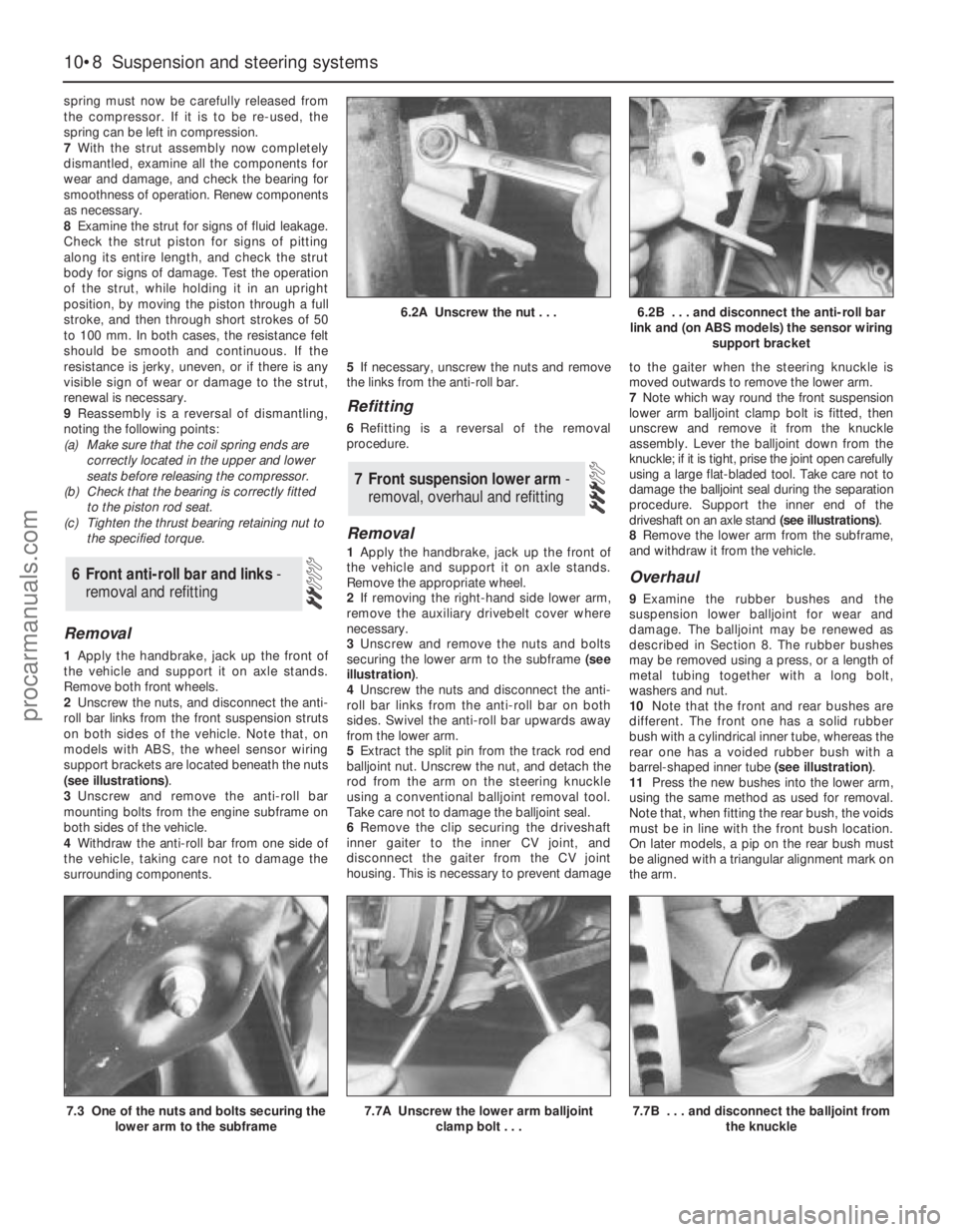
2Unscrew the nuts, and disconnect the anti-
roll bar links from the front suspension struts
on both sides of the vehicle. Note that, on
models with ABS, the wheel sensor wiring
support brackets are located beneath the nuts
(see illustrations).
3Unscrew and remove the anti-roll bar
mounting bolts from the engine subframe on
both sides of the vehicle.
4Withdraw the anti-roll bar from one side of
the vehicle, taking care not to damage the
surrounding components.5If necessary, unscrew the nuts and remove
the links from the anti-roll bar.
Refitting
6Refitting is a reversal of the removal
procedure.
Removal
1Apply the handbrake, jack up the front of
the vehicle and support it on axle stands.
Remove the appropriate wheel.
2If removing the right-hand side lower arm,
remove the auxiliary drivebelt cover where
necessary.
3Unscrew and remove the nuts and bolts
securing the lower arm to the subframe (see
illustration).
4Unscrew the nuts and disconnect the anti-
roll bar links from the anti-roll bar on both
sides. Swivel the anti-roll bar upwards away
from the lower arm.
5Extract the split pin from the track rod end
balljoint nut. Unscrew the nut, and detach the
rod from the arm on the steering knuckle
using a conventional balljoint removal tool.
Take care not to damage the balljoint seal.
6Remove the clip securing the driveshaft
inner gaiter to the inner CV joint, and
disconnect the gaiter from the CV joint
housing. This is necessary to prevent damageto the gaiter when the steering knuckle is
moved outwards to remove the lower arm.
7Note which way round the front suspension
lower arm balljoint clamp bolt is fitted, then
unscrew and remove it from the knuckle
assembly. Lever the balljoint down from the
knuckle; if it is tight, prise the joint open carefully
using a large flat-bladed tool. Take care not to
damage the balljoint seal during the separation
procedure. Support the inner end of the
driveshaft on an axle stand (see illustrations).
8Remove the lower arm from the subframe,
and withdraw it from the vehicle.
Overhaul
9Examine the rubber bushes and the
suspension lower balljoint for wear and
damage. The balljoint may be renewed as
described in Section 8. The rubber bushes
may be removed using a press, or a length of
metal tubing together with a long bolt,
washers and nut.
10Note that the front and rear bushes are
different. The front one has a solid rubber
bush with a cylindrical inner tube, whereas the
rear one has a voided rubber bush with a
barrel-shaped inner tube (see illustration).
11Press the new bushes into the lower arm,
using the same method as used for removal.
Note that, when fitting the rear bush, the voids
must be in line with the front bush location.
On later models, a pip on the rear bush must
be aligned with a triangular alignment mark on
the arm.
7 Front suspension lower arm -
removal, overhaul and refitting
6 Front anti-roll bar and links -
removal and refitting
10•8 Suspension and steering systems
6.2A Unscrew the nut . . .6.2B . . . and disconnect the anti-roll bar
link and (on ABS models) the sensor wiring
support bracket
7.3 One of the nuts and bolts securing the
lower arm to the subframe7.7A Unscrew the lower arm balljoint
clamp bolt . . .7.7B . . . and disconnect the balljoint from
the knuckle
procarmanuals.com