1993 FORD MONDEO heating
[x] Cancel search: heatingPage 3 of 279

REPAIRS & OVERHAUL
Engine and Associated Systems
In-car engine repair procedures Page 2A•1
Engine removal and general engine overhaul procedures Page 2B•1
Cooling, heating and air conditioning systems Page3•1
Fuel and exhaust systems Page 4•1
Engine electrical systems Page 5•1
Emissions control systems Page 6•1
Transmission
Manual transmission Page 7A•1
Automatic transmission Page7B•1
Clutch and driveshafts Page 8•1
Brakes
Braking systemPage 9•1
Suspension
Suspension and steering systems Page 10•1
Body Equipment
Bodywork and fittings Page 11•1
Electrical
Body electrical systems Page 12•1
Wiring DiagramsPage 12•24
REFERENCE
Tools and Working Facilities Page REF• 1
General Repair Procedures Page REF• 4
Buying spare parts and vehicle identification numbers PageREF• 5
Fault FindingPage REF• 6
Glossary of Technical Terms PageREF•13
IndexPage REF•17
Contents
procarmanuals.com
Page 23 of 279
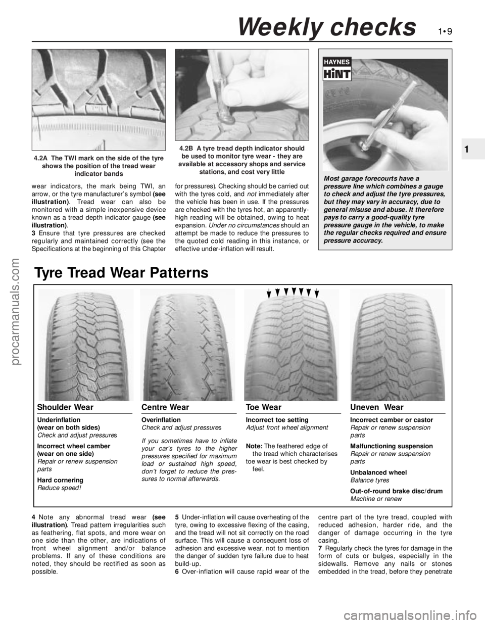
wear indicators, the mark being TWI, an
arrow, or the tyre manufacturer’s symbol (see
illustration). Tread wear can also be
monitored with a simple inexpensive device
known as a tread depth indicator gauge (see
illustration).
3Ensure that tyre pressures are checked
regularly and maintained correctly (see the
Specifications at the beginning of this Chapterfor pressures). Checking should be carried out
with the tyres cold, and notimmediately after
the vehicle has been in use. If the pressures
are checked with the tyres hot, an apparently-
high reading will be obtained, owing to heat
expansion. Under no circumstancesshould an
attempt be made to reduce the pressures to
the quoted cold reading in this instance, or
effective under-inflation will result.
1•9
1
Tyre Tread Wear Patterns
Shoulder Wear
Underinflation
(wear on both sides)
Check and adjust pressures
Incorrect wheel camber
(wear on one side)
Repair or renew suspension
parts
Hard cornering
Reduce speed!
Centre Wear
Overinflation
Check and adjust pressures
If you sometimes have to inflate
your car’s tyres to the higher
pressures specified for maximum
load or sustained high speed,
don’t forget to reduce the pres-
sures to normal afterwards.
Toe Wear
Incorrect toe setting
Adjust front wheel alignment
Note: The feathered edge of
the tread which characterises
toe wear is best checked by
feel.
Uneven Wear
Incorrect camber or castor
Repair or renew suspension
parts
Malfunctioning suspension
Repair or renew suspension
parts
Unbalanced wheel
Balance tyres
Out-of-round brake disc/drum
Machine or renew
4.2A The TWI mark on the side of the tyre
shows the position of the tread wear
indicator bands
4.2B A tyre tread depth indicator should
be used to monitor tyre wear - they are
available at accessory shops and service
stations, and cost very little
Weekly checks
Most garage forecourts have a
pressure line which combines a gauge
to check and adjust the tyre pressures,
but they may vary in accuracy, due to
general misuse and abuse. It therefore
pays to carry a good-quality tyre
pressure gauge in the vehicle, to make
the regular checks required and ensure
pressure accuracy.
4Note any abnormal tread wear (see
illustration). Tread pattern irregularities such
as feathering, flat spots, and more wear on
one side than the other, are indications of
front wheel alignment and/or balance
problems. If any of these conditions are
noted, they should be rectified as soon as
possible.5Under-inflation will cause overheating of the
tyre, owing to excessive flexing of the casing,
and the tread will not sit correctly on the road
surface. This will cause a consequent loss of
adhesion and excessive wear, not to mention
the danger of sudden tyre failure due to heat
build-up.
6Over-inflation will cause rapid wear of thecentre part of the tyre tread, coupled with
reduced adhesion, harder ride, and the
danger of damage occurring in the tyre
casing.
7Regularly check the tyres for damage in the
form of cuts or bulges, especially in the
sidewalls. Remove any nails or stones
embedded in the tread, before they penetrate
procarmanuals.com
Page 30 of 279
comb” or compressed air to clean the
condenser.
Warning: Wear eye protection
when using compressed air!
(d) Check that the drain tube from the front
of the evaporator is clear - note that it is
normal to have clear fluid (water) dripping
from this while the system is in operation,
to the extent that quite a large puddle can
be left under the vehicle when it is parked.
2It’s a good idea to operate the system forabout 30 minutes at least once a month,
particularly during the winter. Long term
non-use can cause hardening, and
subsequent failure, of the seals.
3Because of the complexity of the air
conditioning system and the special
equipment necessary to service it, in-depth
fault diagnosis and repairs are not included in
this manual. For more complete information
on the air conditioning system, refer to the
Haynes Automotive Heating and Air
Conditioning Manual.
4The most common cause of poor cooling is
simply a low system refrigerant charge. If a
noticeable drop in cool air output occurs, the
following quick check will help you determine
if the refrigerant level is low.
5Warm the engine up to normal operating
temperature.
6Place the air conditioning temperature
selector at the coldest setting, and put the
blower at the highest setting. Open the doors
- to make sure the air conditioning system
doesn’t cycle off as soon as it cools the
passenger compartment.
7With the compressor engaged - the clutch
will make an audible click, and the centre of
the clutch will rotate - feel the inlet and outlet
pipes at the compressor. One side should be
cold, and one hot. If there’s no perceptible
difference between the two pipes, there’s
something wrong with the compressor or the
system. It might be a low charge - it might be
something else. Take the vehicle to a dealer
service department or an automotive air
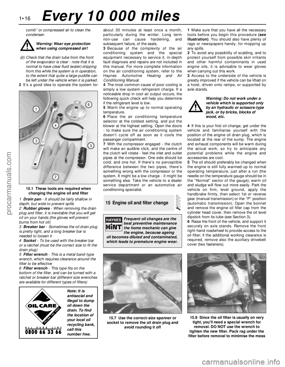
conditioning specialist.1Make sure that you have all the necessary
tools before you begin this procedure (see
illustration). You should also have plenty of
rags or newspapers handy, for mopping up
any spills.
2To avoid any possibility of scalding, and to
protect yourself from possible skin irritants
and other harmful contaminants in used
engine oils, it is advisable to wear gloves
when carrying out this work.
3Access to the underside of the vehicle is
greatly improved if the vehicle can be lifted on
a hoist, driven onto ramps, or supported by
axle stands.
Warning: Do not work under a
vehicle which is supported only
by an hydraulic or scissors-type
jack, or by bricks, blocks of
wood, etc.
4If this is your first oil change, get under the
vehicle and familiarise yourself with the
position of the engine oil drain plug, which is
located at the rear of the sump. The engine
and exhaust components will be warm during
the actual work, so try to anticipate any
potential problems while the engine and
accessories are cool.
5The oil should preferably be changed when
the engine is still fully warmed-up to normal
operating temperature, just after a run (the
needle on the temperature gauge should be in
the “Normal” sector of the gauge); warm oil
and sludge will flow out more easily. Park the
vehicle on firm, level ground, apply the
handbrake firmly, then select 1st or reverse
gear (manual transmission) or the “P” position
(automatic transmission). Open the bonnet
and remove the engine oil filler cap from the
cylinder head cover, then remove the oil level
dipstick from its tube (see Section 3).
6Raise the front of the vehicle, and support it
securely on axle stands. Remove the front
right-hand roadwheel to provide access to the
oil filter; if the additional working clearance is
required, remove also the auxiliary drivebelt
cover (two fasteners).
15 Engine oil and filter change
1•16
15.1 These tools are required when
changing the engine oil and filter
1Drain pan- It should be fairly shallow in
depth, but wide to prevent spills
2Rubber gloves- When removing the drain
plug and filter, it is inevitable that you will get
oil on your hands (the gloves will prevent
burns from hot oil)
3Breaker bar- Sometimes the oil drain plug
is pretty tight, and a long breaker bar is
needed to loosen it
4Socket- To be used with the breaker bar
or a ratchet (must be the correct size to fit the
drain plug)
5Filter wrench- This is a metal band-type
wrench, which requires clearance around the
filter to be effective
6Filter wrench- This type fits on the
bottom of the filter, and can be turned with a
ratchet or breaker bar (different size wrenches
are available for different types of filters)
15.7 Use the correct-size spanner or
socket to remove the oil drain plug and
avoid rounding it off15.9 Since the oil filter is usually on very
tight, you’ll need a special wrench for
removal. DO NOT use the wrench to
tighten the new filter. Pack rag under the
filter before removal to minimise the mess
Every 10 000 miles
Frequent oil changes are the
best preventive maintenance
the home mechanic can give
the engine, because ageing
oil becomes diluted and contaminated,
which leads to premature engine wear.
Note: It is
antisocial and
illegal to dump
oil down the
drain. To find
the location of
your local oil
recycling bank,
call this
number free.
procarmanuals.com
Page 33 of 279
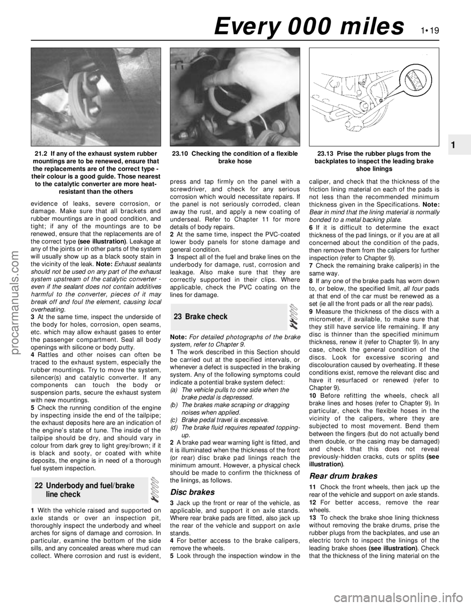
evidence of leaks, severe corrosion, or
damage. Make sure that all brackets and
rubber mountings are in good condition, and
tight; if any of the mountings are to be
renewed, ensure that the replacements are of
the correct type (see illustration). Leakage at
any of the joints or in other parts of the system
will usually show up as a black sooty stain in
the vicinity of the leak. Note:Exhaust sealants
should not be used on any part of the exhaust
system upstream of the catalytic converter -
even if the sealant does not contain additives
harmful to the converter, pieces of it may
break off and foul the element, causing local
overheating.
3At the same time, inspect the underside of
the body for holes, corrosion, open seams,
etc. which may allow exhaust gases to enter
the passenger compartment. Seal all body
openings with silicone or body putty.
4Rattles and other noises can often be
traced to the exhaust system, especially the
rubber mountings. Try to move the system,
silencer(s) and catalytic converter. If any
components can touch the body or
suspension parts, secure the exhaust system
with new mountings.
5Check the running condition of the engine
by inspecting inside the end of the tailpipe;
the exhaust deposits here are an indication of
the engine’s state of tune. The inside of the
tailpipe should be dry, and should vary in
colour from dark grey to light grey/brown; if it
is black and sooty, or coated with white
deposits, the engine is in need of a thorough
fuel system inspection.
1With the vehicle raised and supported on
axle stands or over an inspection pit,
thoroughly inspect the underbody and wheel
arches for signs of damage and corrosion. In
particular, examine the bottom of the side
sills, and any concealed areas where mud can
collect. Where corrosion and rust is evident,press and tap firmly on the panel with a
screwdriver, and check for any serious
corrosion which would necessitate repairs. If
the panel is not seriously corroded, clean
away the rust, and apply a new coating of
underseal. Refer to Chapter 11 for more
details of body repairs.
2At the same time, inspect the PVC-coated
lower body panels for stone damage and
general condition.
3Inspect all of the fuel and brake lines on the
underbody for damage, rust, corrosion and
leakage. Also make sure that they are
correctly supported in their clips. Where
applicable, check the PVC coating on the
lines for damage.
Note:For detailed photographs of the brake
system, refer to Chapter 9.
1The work described in this Section should
be carried out at the specified intervals, or
whenever a defect is suspected in the braking
system. Any of the following symptoms could
indicate a potential brake system defect:
(a) The vehicle pulls to one side when the
brake pedal is depressed.
(b) The brakes make scraping or dragging
noises when applied.
(c) Brake pedal travel is excessive.
(d) The brake fluid requires repeated topping-
up.
2A brake pad wear warning light is fitted, and
it is illuminated when the thickness of the front
(or rear) disc brake pad linings reach the
minimum amount. However, a physical check
should be made to confirm the thickness of
the linings, as follows.
Disc brakes
3Jack up the front or rear of the vehicle, as
applicable, and support it on axle stands.
Where rear brake pads are fitted, also jack up
the rear of the vehicle and support on axle
stands.
4For better access to the brake calipers,
remove the wheels.
5Look through the inspection window in thecaliper, and check that the thickness of the
friction lining material on each of the pads is
not less than the recommended minimum
thickness given in the Specifications. Note:
Bear in mind that the lining material is normally
bonded to a metal backing plate.
6If it is difficult to determine the exact
thickness of the pad linings, or if you are at all
concerned about the condition of the pads,
then remove them from the calipers for further
inspection (refer to Chapter 9).
7Check the remaining brake caliper(s) in the
same way.
8If any one of the brake pads has worn down
to, or below, the specified limit, all fourpads
at that end of the car must be renewed as a
set (ie all the front pads or all the rear pads).
9Measure the thickness of the discs with a
micrometer, if available, to make sure that
they still have service life remaining. If any
disc is thinner than the specified minimum
thickness, renew it (refer to Chapter 9). In any
case, check the general condition of the
discs. Look for excessive scoring and
discolouration caused by overheating. If these
conditions exist, remove the relevant disc and
have it resurfaced or renewed (refer to
Chapter 9).
10Before refitting the wheels, check all
brake lines and hoses (refer to Chapter 9). In
particular, check the flexible hoses in the
vicinity of the calipers, where they are
subjected to most movement. Bend them
between the fingers (but do not actually bend
them double, or the casing may be damaged)
and check that this does not reveal
previously-hidden cracks, cuts or splits (see
illustration).
Rear drum brakes
11Chock the front wheels, then jack up the
rear of the vehicle and support on axle stands.
12For better access, remove the rear
wheels.
13To check the brake shoe lining thickness
without removing the brake drums, prise the
rubber plugs from the backplates, and use an
electric torch to inspect the linings of the
leading brake shoes (see illustration). Check
that the thickness of the lining material on the
23 Brake check
22 Underbody and fuel/brake
line check
1•19
121.2 If any of the exhaust system rubber
mountings are to be renewed, ensure that
the replacements are of the correct type -
their colour is a good guide. Those nearest
to the catalytic converter are more heat-
resistant than the others23.10 Checking the condition of a flexible
brake hose23.13 Prise the rubber plugs from the
backplates to inspect the leading brake
shoe linings
Every 000 miles
procarmanuals.com
Page 36 of 279
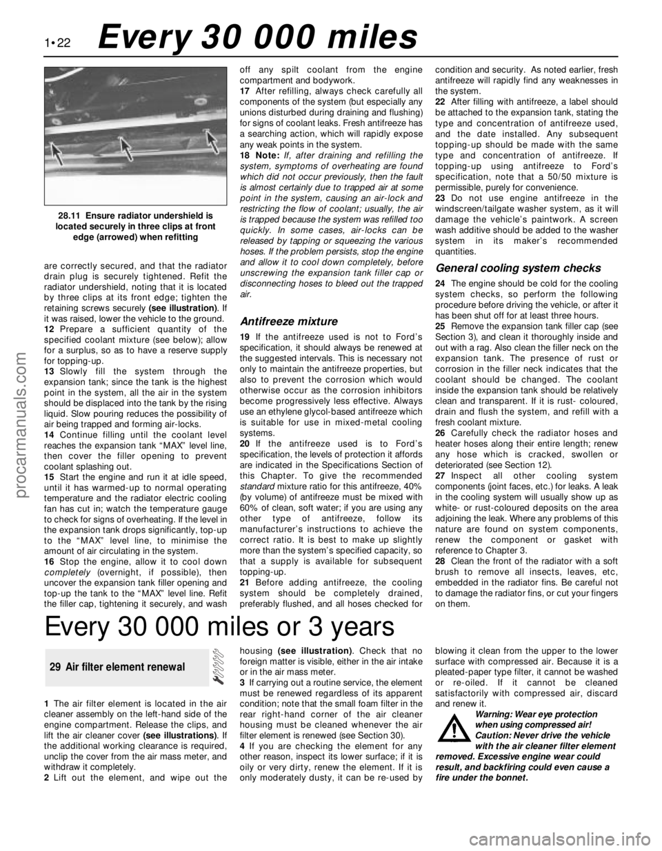
are correctly secured, and that the radiator
drain plug is securely tightened. Refit the
radiator undershield, noting that it is located
by three clips at its front edge; tighten the
retaining screws securely (see illustration). If
it was raised, lower the vehicle to the ground.
12Prepare a sufficient quantity of the
specified coolant mixture (see below); allow
for a surplus, so as to have a reserve supply
for topping-up.
13Slowly fill the system through the
expansion tank; since the tank is the highest
point in the system, all the air in the system
should be displaced into the tank by the rising
liquid. Slow pouring reduces the possibility of
air being trapped and forming air-locks.
14Continue filling until the coolant level
reaches the expansion tank “MAX” level line,
then cover the filler opening to prevent
coolant splashing out.
15Start the engine and run it at idle speed,
until it has warmed-up to normal operating
temperature and the radiator electric cooling
fan has cut in; watch the temperature gauge
to check for signs of overheating. If the level in
the expansion tank drops significantly, top-up
to the “MAX” level line, to minimise the
amount of air circulating in the system.
16Stop the engine, allow it to cool down
completely(overnight, if possible), then
uncover the expansion tank filler opening and
top-up the tank to the “MAX” level line. Refit
the filler cap, tightening it securely, and washoff any spilt coolant from the engine
compartment and bodywork.
17After refilling, always check carefully all
components of the system (but especially any
unions disturbed during draining and flushing)
for signs of coolant leaks. Fresh antifreeze has
a searching action, which will rapidly expose
any weak points in the system.
18 Note:If, after draining and refilling the
system, symptoms of overheating are found
which did not occur previously, then the fault
is almost certainly due to trapped air at some
point in the system, causing an air-lock and
restricting the flow of coolant; usually, the air
is trapped because the system was refilled too
quickly. In some cases, air-locks can be
released by tapping or squeezing the various
hoses. If the problem persists, stop the engine
and allow it to cool down completely, before
unscrewing the expansion tank filler cap or
disconnecting hoses to bleed out the trapped
air.
Antifreeze mixture
19If the antifreeze used is not to Ford’s
specification, it should always be renewed at
the suggested intervals. This is necessary not
only to maintain the antifreeze properties, but
also to prevent the corrosion which would
otherwise occur as the corrosion inhibitors
become progressively less effective. Always
use an ethylene glycol-based antifreeze which
is suitable for use in mixed-metal cooling
systems.
20If the antifreeze used is to Ford’s
specification, the levels of protection it affords
are indicated in the Specifications Section of
this Chapter. To give the recommended
standardmixture ratio for this antifreeze, 40%
(by volume) of antifreeze must be mixed with
60% of clean, soft water; if you are using any
other type of antifreeze, follow its
manufacturer’s instructions to achieve the
correct ratio. It is best to make up slightly
more than the system’s specified capacity, so
that a supply is available for subsequent
topping-up.
21Before adding antifreeze, the cooling
system should be completely drained,
preferably flushed, and all hoses checked forcondition and security. As noted earlier, fresh
antifreeze will rapidly find any weaknesses in
the system.
22After filling with antifreeze, a label should
be attached to the expansion tank, stating the
type and concentration of antifreeze used,
and the date installed. Any subsequent
topping-up should be made with the same
type and concentration of antifreeze. If
topping-up using antifreeze to Ford’s
specification, note that a 50/50 mixture is
permissible, purely for convenience.
23Do not use engine antifreeze in the
windscreen/tailgate washer system, as it will
damage the vehicle’s paintwork. A screen
wash additive should be added to the washer
system in its maker’s recommended
quantities.
General cooling system checks
24The engine should be cold for the cooling
system checks, so perform the following
procedure before driving the vehicle, or after it
has been shut off for at least three hours.
25Remove the expansion tank filler cap (see
Section 3), and clean it thoroughly inside and
out with a rag. Also clean the filler neck on the
expansion tank. The presence of rust or
corrosion in the filler neck indicates that the
coolant should be changed. The coolant
inside the expansion tank should be relatively
clean and transparent. If it is rust- coloured,
drain and flush the system, and refill with a
fresh coolant mixture.
26Carefully check the radiator hoses and
heater hoses along their entire length; renew
any hose which is cracked, swollen or
deteriorated (see Section 12).
27Inspect all other cooling system
components (joint faces, etc.) for leaks. A leak
in the cooling system will usually show up as
white- or rust-coloured deposits on the area
adjoining the leak. Where any problems of this
nature are found on system components,
renew the component or gasket with
reference to Chapter 3.
28Clean the front of the radiator with a soft
brush to remove all insects, leaves, etc,
embedded in the radiator fins. Be careful not
to damage the radiator fins, or cut your fingers
on them.
1•22
28.11 Ensure radiator undershield is
located securely in three clips at front
edge (arrowed) when refitting
Every 30 000 miles
Every 30 000 miles or 3 years
1The air filter element is located in the air
cleaner assembly on the left-hand side of the
engine compartment. Release the clips, and
lift the air cleaner cover (see illustrations). If
the additional working clearance is required,
unclip the cover from the air mass meter, and
withdraw it completely.
2Lift out the element, and wipe out thehousing (see illustration). Check that no
foreign matter is visible, either in the air intake
or in the air mass meter.
3If carrying out a routine service, the element
must be renewed regardless of its apparent
condition; note that the small foam filter in the
rear right-hand corner of the air cleaner
housing must be cleaned whenever the air
filter element is renewed (see Section 30).
4If you are checking the element for any
other reason, inspect its lower surface; if it is
oily or very dirty, renew the element. If it is
only moderately dusty, it can be re-used byblowing it clean from the upper to the lower
surface with compressed air. Because it is a
pleated-paper type filter, it cannot be washed
or re-oiled. If it cannot be cleaned
satisfactorily with compressed air, discard
and renew it.
Warning: Wear eye protection
when using compressed air!
Caution: Never drive the vehicle
with the air cleaner filter element
removed. Excessive engine wear could
result, and backfiring could even cause a
fire under the bonnet.
29 Air filter element renewal
procarmanuals.com
Page 55 of 279
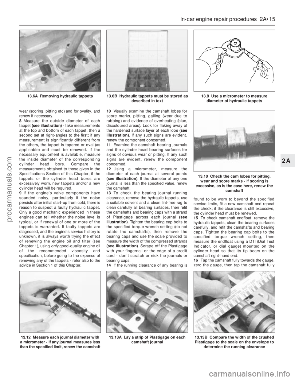
wear (scoring, pitting etc) and for ovality, and
renew if necessary.
8Measure the outside diameter of each
tappet (see illustration)- take measurements
at the top and bottom of each tappet, then a
second set at right-angles to the first; if any
measurement is significantly different from
the others, the tappet is tapered or oval (as
applicable) and must be renewed. If the
necessary equipment is available, measure
the inside diameter of the corresponding
cylinder head bore. Compare the
measurements obtained to those given in the
Specifications Section of this Chapter; if the
tappets or the cylinder head bores are
excessively worn, new tappets and/or a new
cylinder head will be required.
9If the engine’s valve components have
sounded noisy, particularly if the noise
persists after initial start-up from cold, there is
reason to suspect a faulty hydraulic tappet.
Only a good mechanic experienced in these
engines can tell whether the noise level is
typical, or if renewal of one or more of the
tappets is warranted. If faulty tappets are
diagnosed, and the engine’s service history is
unknown, it is always worth trying the effect
of renewing the engine oil and filter (see
Chapter 1), using onlygood-quality engine oil
of the recommended viscosity and
specification, before going to the expense of
renewing any of the tappets - refer also to the
advice in Section 1 of this Chapter.10Visually examine the camshaft lobes for
score marks, pitting, galling (wear due to
rubbing) and evidence of overheating (blue,
discoloured areas). Look for flaking away of
the hardened surface layer of each lobe (see
illustration). If any such signs are evident,
renew the component concerned.
11Examine the camshaft bearing journals
and the cylinder head bearing surfaces for
signs of obvious wear or pitting. If any such
signs are evident, renew the component
concerned.
12Using a micrometer, measure the
diameter of each journal at several points
(see illustration). If the diameter of any one
journal is less than the specified value, renew
the camshaft.
13To check the bearing journal running
clearance, remove the hydraulic tappets, use
a suitable solvent and a clean lint-free rag to
clean carefully all bearing surfaces, then refit
the camshafts and bearing caps with a strand
of Plastigage across each journal (see
illustration). Tighten the bearing cap bolts to
the specified torque wrench setting (do not
rotate the camshafts), then remove the
bearing caps and use the scale provided to
measure the width of the compressed strands
(see illustration). Scrape off the Plastigage
with your fingernail or the edge of a credit
card - don’t scratch or nick the journals or
bearing caps.
14If the running clearance of any bearing isfound to be worn to beyond the specified
service limits, fit a new camshaft and repeat
the check; if the clearance is still excessive,
the cylinder head must be renewed.
15To check camshaft endfloat, remove the
hydraulic tappets, clean the bearing surfaces
carefully, and refit the camshafts and bearing
caps. Tighten the bearing cap bolts to the
specified torque wrench setting, then
measure the endfloat using a DTI (Dial Test
Indicator, or dial gauge) mounted on the
cylinder head so that its tip bears on the
camshaft right-hand end.
16Tap the camshaft fully towards the gauge,
zero the gauge, then tap the camshaft fully
In-car engine repair procedures 2A•15
2A
13.12 Measure each journal diameter with
a micrometer - if any journal measures less
than the specified limit, renew the camshaft13.13A Lay a strip of Plastigage on each
camshaft journal13.13B Compare the width of the crushed
Plastigage to the scale on the envelope to
determine the running clearance
13.6A Removing hydraulic tappets13.6B Hydraulic tappets must be stored as
described in text13.8 Use a micrometer to measure
diameter of hydraulic tappets
13.10 Check the cam lobes for pitting,
wear and score marks - if scoring is
excessive, as is the case here, renew the
camshaft
procarmanuals.com
Page 83 of 279
Note:Always check first what replacement
parts are available before planning any
overhaul operation; refer to Section 1 of this
Part. A Ford dealer, or a good engine
reconditioning specialist/automotive parts
supplier may be able to suggest alternatives
which will enable you to overcome the lack of
replacement parts.
1Before the inspection process can be
carried out, the piston/connecting rod
assemblies must be cleaned, and the original
piston rings removed from the pistons. The
rings should have smooth, polished working
surfaces, with no dull or carbon-coated
sections (showing that the ring is not sealing
correctly against the bore wall, so allowing
combustion gases to blow by) and no traces
of wear on their top and bottom surfaces. The
end gaps should be clear of carbon, but not
polished (indicating a too-small end gap), and
all the rings (including the elements of the oil
control ring) should be free to rotate in their
grooves, but without excessive up-and-down
movement. If the rings appear to be in good
condition, they are probably fit for further use;
check the end gaps (in an unworn part of the
bore) as described in Section 16. If any of the
rings appears to be worn or damaged, or has
an end gap significantly different from the
specified value, the usual course of action is
to renew all of them as a set. Note:While it is
usual always to renew piston rings when an
engine is overhauled, this of course assumes
that rings are available separately - if not, it
follows that great care must be taken not to
break or damage any of the rings during the
following procedures, and to ensure that each
ring is marked on removal so that it is refitted
onlythe original way up, and onlyto the same
groove.
2Using a piston ring renoval tool, carefully
remove the rings from the pistons. Be careful
not to nick or gouge the pistons in the
process, and mark or label each ring as it is
removed, so that its original top surface canbe identified on reassembly, and so that it can
be returned to its original groove. Take care
also with your hands - piston rings are sharp!
3Scrape all traces of carbon from the top of
the piston. A hand-held wire brush or a piece
of fine emery cloth can be used, once the
majority of the deposits have been scraped
away. Do not, under any circumstances, use a
wire brush mounted in a drill motor to remove
deposits from the pistons - the piston material
is soft, and may be eroded away by the wire
brush.
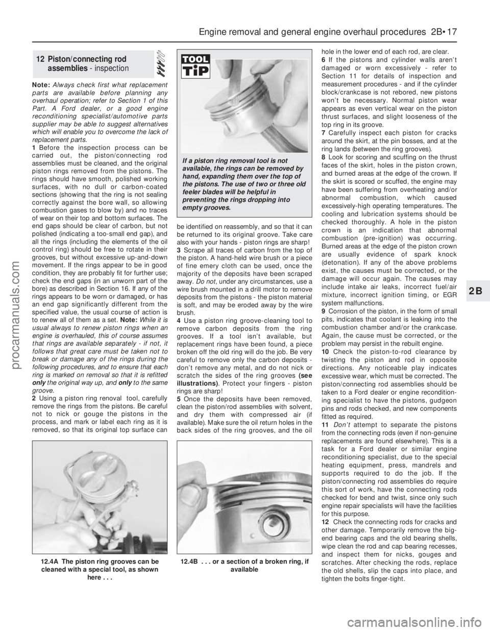
4Use a piston ring groove-cleaning tool to
remove carbon deposits from the ring
grooves. If a tool isn’t available, but
replacement rings have been found, a piece
broken off the old ring will do the job. Be very
careful to remove only the carbon deposits -
don’t remove any metal, and do not nick or
scratch the sides of the ring grooves (see
illustrations). Protect your fingers - piston
rings are sharp!
5Once the deposits have been removed,
clean the piston/rod assemblies with solvent,
and dry them with compressed air (if
available). Make sure the oil return holes in the
back sides of the ring grooves, and the oilhole in the lower end of each rod, are clear.
6If the pistons and cylinder walls aren’t
damaged or worn excessively - refer to
Section 11 for details of inspection and
measurement procedures - and if the cylinder
block/crankcase is not rebored, new pistons
won’t be necessary. Normal piston wear
appears as even vertical wear on the piston
thrust surfaces, and slight looseness of the
top ring in its groove.
7Carefully inspect each piston for cracks
around the skirt, at the pin bosses, and at the
ring lands (between the ring grooves).
8Look for scoring and scuffing on the thrust
faces of the skirt, holes in the piston crown,
and burned areas at the edge of the crown. If
the skirt is scored or scuffed, the engine may
have been suffering from overheating and/or
abnormal combustion, which caused
excessively-high operating temperatures. The
cooling and lubrication systems should be
checked thoroughly. A hole in the piston
crown is an indication that abnormal
combustion (pre-ignition) was occurring.
Burned areas at the edge of the piston crown
are usually evidence of spark knock
(detonation). If any of the above problems
exist, the causes must be corrected, or the
damage will occur again. The causes may
include intake air leaks, incorrect fuel/air
mixture, incorrect ignition timing, or EGR
system malfunctions.
9Corrosion of the piston, in the form of small
pits, indicates that coolant is leaking into the
combustion chamber and/or the crankcase.
Again, the cause must be corrected, or the
problem may persist in the rebuilt engine.
10Check the piston-to-rod clearance by
twisting the piston and rod in opposite
directions. Any noticeable play indicates
excessive wear, which must be corrected. The
piston/connecting rod assemblies should be
taken to a Ford dealer or engine recondition-
ing specialist to have the pistons, gudgeon
pins and rods checked, and new components
fitted as required.
11Don’tattempt to separate the pistons
from the connecting rods (even if non-genuine
replacements are found elsewhere). This is a
task for a Ford dealer or similar engine
reconditioning specialist, due to the special
heating equipment, press, mandrels and
supports required to do the job. If the
piston/connecting rod assemblies do require
this sort of work, have the connecting rods
checked for bend and twist, since only such
engine repair specialists will have the facilities
for this purpose.
12Check the connecting rods for cracks and
other damage. Temporarily remove the big-
end bearing caps and the old bearing shells,
wipe clean the rod and cap bearing recesses,
and inspect them for nicks, gouges and
scratches. After checking the rods, replace
the old shells, slip the caps into place, and
tighten the bolts finger-tight.
12 Piston/connecting rod
assemblies - inspection
Engine removal and general engine overhaul procedures 2B•17
2B
12.4A The piston ring grooves can be
cleaned with a special tool, as shown
here . . .12.4B . . . or a section of a broken ring, if
available
If a piston ring removal tool is not
available, the rings can be removed by
hand, expanding them over the top of
the pistons. The use of two or three old
feeler blades will be helpful in
preventing the rings dropping into
empty grooves.
procarmanuals.com
Page 84 of 279
Note:Always check first what replacement
parts are available before planning any
overhaul operation; refer to Section 1 of this
Part. A Ford dealer, or a good engine
reconditioning specialist/automotive parts
supplier, may be able to suggest alternatives
which will enable you to overcome the lack of
replacement parts.
1Clean the crankshaft, and dry it with
compressed air if available.
Warning: Wear eye protection
when using compressed air! Be
sure to clean the oil holes with a
pipe cleaner or similar probe.
2Check the main and crankpin (big-end)
bearing journals for uneven wear, scoring,
pitting and cracking.
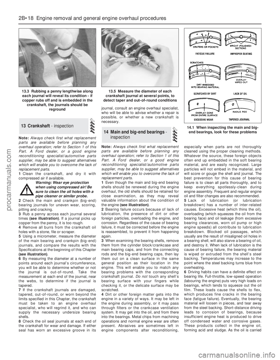
3Rub a penny across each journal several
times (see illustration). If a journal picks up
copper from the penny, it is too rough.
4Remove all burrs from the crankshaft oil
holes with a stone, file or scraper.
5Using a micrometer, measure the diameter
of the main bearing and crankpin (big-end)
journals, and compare the results with the
Specifications at the beginning of this Chapter
(see illustration).
6By measuring the diameter at a number of
points around each journal’s circumference,
you will be able to determine whether or not
the journal is out-of-round. Take the
measurement at each end of the journal, near
the webs, to determine if the journal is
tapered.
7If the crankshaft journals are damaged,
tapered, out-of-round, or worn beyond the
limits specified in this Chapter, the crankshaft
must be taken to an engine overhaul
specialist, who will regrind it, and who can
supply the necessary undersize bearing
shells.
8Check the oil seal journals at each end of
the crankshaft for wear and damage. If either
seal has worn an excessive groove in itsjournal, consult an engine overhaul specialist,
who will be able to advise whether a repair is
possible, or whether a new crankshaft is
necessary.
Note:Always check first what replacement
parts are available before planning any
overhaul operation; refer to Section 1 of this
Part. A Ford dealer, or a good engine
reconditioning specialist/automotive parts
supplier, may be able to suggest alternatives
which will enable you to overcome the lack of
replacement parts.
1Even though the main and big-end bearing
shells should be renewed during the engine
overhaul, the old shells should be retained for
close examination, as they may reveal
valuable information about the condition of
the engine (see illustration).
2Bearing failure occurs because of lack of
lubrication, the presence of dirt or other
foreign particles, overloading the engine, and
corrosion. Regardless of the cause of bearing
failure, it must be corrected before the engine
is reassembled, to prevent it from happening
again.
3When examining the bearing shells, remove
them from the cylinder block/crankcase and
main bearing caps, and from the connecting
rods and the big-end bearing caps, then lay
them out on a clean surface in the same
general position as their location in the
engine. This will enable you to match any
bearing problems with the corresponding
crankshaft journal. Do nottouch any shell’s
bearing surface with your fingers while
checking it, or the delicate surface may be
scratched.
4Dirt or other foreign matter gets into the
engine in a variety of ways. It may be left in
the engine during assembly, or it may pass
through filters or the crankcase ventilation
system. It may get into the oil, and from there
into the bearings. Metal chips from machining
operations and normal engine wear are often
present. Abrasives are sometimes left in
engine components after reconditioning,especially when parts are not thoroughly
cleaned using the proper cleaning methods.
Whatever the source, these foreign objects
often end up embedded in the soft bearing
material, and are easily recognized. Large
particles will not embed in the material, and
will score or gouge the shell and journal. The
best prevention for this cause of bearing
failure is to clean all parts thoroughly, and to
keep everything spotlessly-clean during
engine assembly. Frequent and regular engine
oil and filter changes are also recommended.
5Lack of lubrication (or lubrication
breakdown) has a number of inter-related
causes. Excessive heat (which thins the oil),
overloading (which squeezes the oil from the
bearing face) and oil leakage (from excessive
bearing clearances, worn oil pump or high
engine speeds) all contribute to lubrication
breakdown. Blocked oil passages, which
usually are the result of misaligned oil holes in
a bearing shell, will also starve a bearing of oil,
and destroy it. When lack of lubrication is the
cause of bearing failure, the bearing material
is wiped or extruded from the shell’s steel
backing. Temperatures may increase to the
point where the steel backing turns blue from
overheating.
6Driving habits can have a definite effect on
bearing life. Full-throttle, low-speed operation
(labouring the engine) puts very high loads on
bearings, which tends to squeeze out the oil
film. These loads cause the shells to flex,
which produces fine cracks in the bearing
face (fatigue failure). Eventually, the bearing
material will loosen in pieces, and tear away
from the steel backing. Short-distance driving
leads to corrosion of bearings, because
insufficient engine heat is produced to drive
off condensed water and corrosive gases.
These products collect in the engine oil,
forming acid and sludge. As the oil is carried
14 Main and big-end bearings-
inspection
13 Crankshaft - inspection
2B•18 Engine removal and general engine overhaul procedures
13.3 Rubbing a penny lengthwise along
each journal will reveal its condition - if
copper rubs off and is embedded in the
crankshaft, the journals should be
reground13.5 Measure the diameter of each
crankshaft journal at several points, to
detect taper and out-of-round conditions
14.1 When inspecting the main and big-
end bearings, look for these problems
procarmanuals.com