1993 FORD MONDEO steering wheel adjustment
[x] Cancel search: steering wheel adjustmentPage 75 of 279
gear linkage heat shield. Reconnect the
gearchange linkage and transmission support
rods to the transmission, adjusting the linkage
using the marks made on removal (see
Chapter 7, Part A, for details).
56Re-install the remaining components and
fasteners in the reverse order of removal.
57Add coolant, engine oil and transmission
fluids as needed (see Chapter 1).
58Run the engine, and check for proper
operation and the absence of leaks. Shut off
the engine, and recheck the fluid levels.
59Remember that, since the front suspension
subframe and steering gear have been
disturbed, the wheel alignment and steering
angles must be checked fully and carefully as
soon as possible, with any necessary
adjustments being made. This operation is best
carried out by an experienced mechanic, using
proper checking equipment; the vehicle should
therefore be taken to a Ford dealer or similarly-
qualified person for attention.
1It is much easier to dismantle and work on
the engine if it is mounted on a portable engine
stand. These stands can often be hired from a
tool hire shop. Before the engine is mounted
on a stand, the flywheel/driveplate should be
removed (Part A of this Chapter, Section 21)
so that the stand bolts can be tightened into
the end of the cylinder block/crankcase.
2If a stand is not available, it is possible to
dismantle the engine with it mounted on
blocks, on a sturdy workbench or on the floor.
Be extra-careful not to tip or drop the engine
when working without a stand.
3If you are going to obtain a reconditioned
engine, all external components must be
removed first, to be transferred to the
replacement engine (just as they will if you are
doing a complete engine overhaul yourself).
Note:When removing the external
components from the engine, pay close
attention to details that may be helpful or
important during refitting. Note the fitted
position of gaskets, seals, spacers, pins,
washers, bolts and other small items.These
external components include the following:
(a) Alternator and brackets (Chapter 5).
(b) HT leads and spark plugs (Chapter 1).
(c) Thermostat and housing (Chapter 3).
(d) Dipstick tube.
(e) Fuel injection system components
(Chapter 4).
(f) All electrical switches and sensors - refer
to the appropriate Chapter.
(g) Inlet and exhaust manifolds (Part A of this
Chapter).
(h) Oil filter (Chapter 1).
(i) Engine/transmission mounting brackets
(Part A of this Chapter, Section 22).
(j) Flywheel/driveplate (Part A of this
Chapter, Section 21).
4If you are obtaining a “short” engine (whichconsists of the engine cylinder
block/crankcase, crankshaft, pistons and
connecting rods all assembled), then the
cylinder head, sump, oil pump, and timing belt
will have to be removed also.
5If you are planning a complete overhaul, the
engine can be dismantled and the internal
components removed in the following order.
(a) Inlet and exhaust manifolds (Part A of this
Chapter).
(b) Timing belt, toothed pulleys and
tensioner, and timing belt inner cover
(Part A of this Chapter).
(c) Cylinder head (Part A of this Chapter,
Section 14).
(d) Flywheel/driveplate (Part A of this
Chapter, Section 21).
(e) Sump (Part A of this Chapter, Section 15).
(f) Oil pump (Part A of this Chapter, Sec-
tion 16).
(g) Piston/connecting rod assemblies
(Section 9).
(h) Crankshaft (Section 10).
6Before beginning the dismantling andoverhaul procedures, make sure that you have
all of the correct tools necessary. Refer to the
introductory pages at the beginning of this
manual for further information.
Note:New and reconditioned cylinder heads
are available from the manufacturers, and
from engine overhaul specialists. Due to the
fact that some specialist tools are required for
the dismantling and inspection procedures,
and new components may not be readily
available (refer to Section 1 of this Part), it may
be more practical and economical for the
home mechanic to purchase a reconditioned
head, rather than to dismantle, inspect and
recondition the original head.
1Remove the camshafts and hydraulic
tappets (Part A of this Chapter, Section 13),
being careful to store the hydraulic tappets as
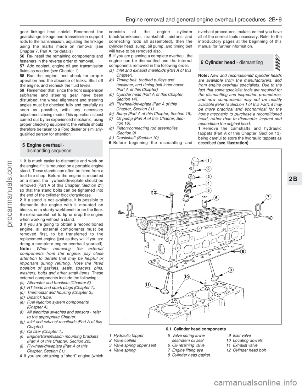
described (see illustration).
6 Cylinder head - dismantling
5 Engine overhaul-
dismantling sequence
Engine removal and general engine overhaul procedures 2B•9
2B
6.1 Cylinder head components
1 Hydraulic tappet
2 Valve collets
3 Valve spring upper seat
4 Valve spring5 Valve spring lower
seat/stem oil seal
6 Oil-retaining valve
7 Engine lifting eye
8 Cylinder head gasket9 Inlet valve
10 Locating dowels
11 Exhaust valve
12 Cylinder head bolt
procarmanuals.com
Page 149 of 279
15Unscrew the two rearmost canister
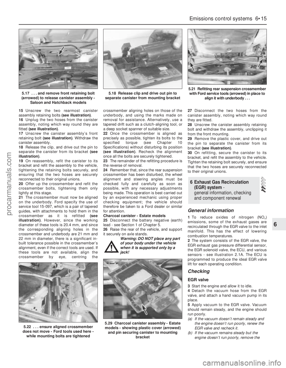
assembly retaining bolts (see illustration).
16Unplug the two hoses from the canister
assembly, noting which way round they are
fitted (see illustration).
17Unscrew the canister assembly’s front
retaining bolt (see illustration). Withdraw the
canister assembly.
18Release the clip, and drive out the pin to
separate the canister from its bracket (see
illustration).
19On reassembly, refit the canister to its
bracket and refit the assembly to the vehicle,
tightening the retaining bolts securely, and
ensuring that the two hoses are securely
reconnected to their original unions.
20Offer up the crossmember and refit the
crossmember bolts, tightening them only
lightly at this stage.
21The crossmember must now be aligned
on the underbody. Ford specify the use of
service tool 15-097, which is a pair of tapered
guides, with attachments to hold them in the
crossmember as it is refitted (see
illustration). However, since the working
diameter of these tools is 20.4 mm, and since
the corresponding aligning holes in the
crossmember and underbody are 21 mm and
22 mm in diameter, there is a significant in-
built tolerance possible in the crossmember’s
alignment, even if the correct tools are used. If
these tools are not available, align the
crossmember by eye, centring thecrossmember aligning holes on those of the
underbody, and using the marks made on
removal for assistance. Alternatively, use a
tapered drift such as a clutch-aligning tool, or
a deep socket spanner of suitable size.
22Once the crossmember is aligned as
precisely as possible, tighten its bolts to the
specified torque (see Chapter 10
Specifications) without disturbing its position
(see illustration). Recheck the alignment
once all the bolts are securely tightened.
23The remainder of the refitting procedure is
the reverse of removal.
24Remember that, since the rear suspension
crossmember has been disturbed, the wheel
alignment and steering angles must be
checked fully and carefully as soon as
possible, with any necessary adjustments
being made. This operation is best carried out
by an experienced mechanic using proper
checking equipment; the vehicle should
therefore be taken to a Ford dealer or similar
for attention.
Charcoal canister - Estate models
25Disconnect the battery negative (earth)
lead - see Section 1 of Chapter 5.
26Raise the rear of the vehicle, and support
it securely on axle stands.
Warning: DO NOT place any part
of your body under the vehicle
when it is supported only by a
jack!27Disconnect the two hoses from the
canister assembly, noting which way round
they are fitted.
28Unscrew the canister assembly retaining
bolt and withdraw the assembly, unclipping it
from the front mounting.
29Remove the plastic cover, and drive out
the pin to separate the canister from its
bracket (see illustration).
30On refitting, secure the canister to its
bracket, and refit the assembly to the vehicle.
Tighten the retaining bolt securely, and ensure
that the two hoses are securely reconnected
to their original unions.
General information
1To reduce oxides of nitrogen (NOx)
emissions, some of the exhaust gases are
recirculated through the EGR valve to the inlet
manifold. This has the effect of lowering
combustion temperatures.
2The system consists of the EGR valve, the
EGR exhaust gas pressure differential sensor,
the EGR solenoid valve, the ECU, and various
sensors - see illustration 2.1A. The ECU is
programmed to produce the ideal EGR valve
lift for each operating condition.
Checking
EGR valve
3Start the engine and allow it to idle.
4Detach the vacuum hose from the EGR
valve, and attach a hand vacuum pump in its
place.
5Apply vacuum to the EGR valve. Vacuum
should remain steady, and the engine should
run poorly.
(a) If the vacuum doesn’t remain steady and
the engine doesn’t run poorly, renew the
EGR valve and recheck it.
(b) If the vacuum remains steady but the
engine doesn’t run poorly, remove the
6 Exhaust Gas Recirculation
(EGR) system-
general information, checking
and component renewal
Emissions control systems 6•15
6
5.22 . . . ensure aligned crossmember
does not move - Ford tools used here -
while mounting bolts are tightened5.29 Charcoal canister assembly - Estate
models - showing plastic cover (arrowed)
and pin securing canister to mounting
bracket
5.17 . . . and remove front retaining bolt
(arrowed) to release canister assembly -
Saloon and Hatchback models5.18 Release clip and drive out pin to
separate canister from mounting bracket5.21 Refitting rear suspension crossmember
with Ford service tools (arrowed) in place to
align it with underbody . . .
procarmanuals.com
Page 155 of 279
Chapter 10 Suspension and steering systems
Front anti-roll bar and links - removal and refitting . . . . . . . . . . . . . . 6
Front hub and bearings - inspection and renewal . . . . . . . . . . . . . . 3
Front suspension lower arm - removal, overhaul and refitting . . . . . 7
Front suspension lower arm balljoint - renewal . . . . . . . . . . . . . . . . 8
Front suspension strut - overhaul . . . . . . . . . . . . . . . . . . . . . . . . . . . 5
Front suspension strut - removal and refitting . . . . . . . . . . . . . . . . . 4
General information . . . . . . . . . . . . . . . . . . . . . . . . . . . . . . . . . . . . . . 1
Power steering fluid level check . . . . . . . . . . . . . . . . . See Chapter 1
Power steering gear (all except left-hand-drive models
with ABS) - removal and refitting . . . . . . . . . . . . . . . . . . . . . . . . . . 30
Power steering gear (left-hand-drive models with ABS) -
removal and refitting . . . . . . . . . . . . . . . . . . . . . . . . . . . . . . . . . . . 31
Power steering gear rubber gaiters - renewal . . . . . . . . . . . . . . . . . . 32
Power steering hydraulic system - bleeding . . . . . . . . . . . . . . . . . . . 33
Power steering pump - removal and refitting . . . . . . . . . . . . . . . . . . 34
Rear anti-roll bar and links (Estate models) - removal and refitting . 20
Rear anti-roll bar and links (Saloon/Hatchback models) -
removal and refitting . . . . . . . . . . . . . . . . . . . . . . . . . . . . . . . . . . . 13
Rear coil spring (Estate models) - removal and refitting . . . . . . . . . . 21
Rear hub and bearings (Estate models) - inspection and renewal . . 17
Rear hub and bearings (Saloon/Hatchback models) -
inspection and renewal . . . . . . . . . . . . . . . . . . . . . . . . . . . . . . . . . 9
Rear shock absorber (Estate models) - removal, testing and refitting . 19
Rear suspension crossmember (Estate models) - removal
and refitting . . . . . . . . . . . . . . . . . . . . . . . . . . . . . . . . . . . . . . . . . . 26
Rear suspension crossmember (Saloon/Hatchback models) -
removal and refitting . . . . . . . . . . . . . . . . . . . . . . . . . . . . . . . . . . . 16Rear suspension front lower arm (Estate models) - removal
and refitting . . . . . . . . . . . . . . . . . . . . . . . . . . . . . . . . . . . . . . . . . . 23
Rear suspension knuckle (Estate models) - removal and refitting . . 18
Rear suspension knuckle (Saloon/Hatchback models) - removal
and refitting . . . . . . . . . . . . . . . . . . . . . . . . . . . . . . . . . . . . . . . . . . 10
Rear suspension lower arms (Saloon/Hatchback models) -
removal and refitting . . . . . . . . . . . . . . . . . . . . . . . . . . . . . . . . . . . 14
Rear suspension rear lower arm (Estate models) - removal
and refitting . . . . . . . . . . . . . . . . . . . . . . . . . . . . . . . . . . . . . . . . . . 22
Rear suspension strut (Saloon/Hatchback models) - overhaul . . . . . 12
Rear suspension strut (Saloon/Hatchback models) -
removal and refitting . . . . . . . . . . . . . . . . . . . . . . . . . . . . . . . . . . . 11
Rear suspension tie-bar (Estate models) - removal and refitting . . . 25
Rear suspension tie-bar (Saloon/Hatchback models) -
removal and refitting . . . . . . . . . . . . . . . . . . . . . . . . . . . . . . . . . . . 15
Rear suspension upper arm (Estate models) - removal
and refitting . . . . . . . . . . . . . . . . . . . . . . . . . . . . . . . . . . . . . . . . . . 24
Steering column - removal, inspection and refitting . . . . . . . . . . . . . 28
Steering column flexible coupling - removal and refitting . . . . . . . . . 29
Steering knuckle and hub assembly - removal and refitting . . . . . . . 2
Steering, suspension and wheel check . . . . . . . . . . . . See Chapter 1
Steering wheel - removal and refitting . . . . . . . . . . . . . . . . . . . . . . . 27
Track rod end - renewal . . . . . . . . . . . . . . . . . . . . . . . . . . . . . . . . . . 35
Tyre condition and tyre pressure checks . . . . . . . . . . . See Chapter 1
Wheel alignment and steering angles - general information . . . . . . . 36
Front wheel alignment
Toe setting:
Tolerance allowed before resetting required . . . . . . . . . . . . . . . . . . . . 0.5 mm to 3.5 mm toe-out (0°05’ to 0°35’ toe-out)
Adjustment setting (if required) . . . . . . . . . . . . . . . . . . . . . . . . . . . . . . 2.0 mm ± 1.0 mm toe-out (0°20’ ± 0°10’ toe-out)
Rear wheel alignment
Toe setting:
Tolerance allowed before resetting required:
Saloon/Hatchback . . . . . . . . . . . . . . . . . . . . . . . . . . . . . . . . . . . . . . 3.9 mm toe-in to 0.1 mm toe-out (0°38’ toe-in to 0°02’ toe-out)
Estate . . . . . . . . . . . . . . . . . . . . . . . . . . . . . . . . . . . . . . . . . . . . . . . . 2.7 mm toe-in to 1.3 mm toe-out (0°27’ toe-in to 0°13’ toe-out)
Adjustment setting (if required):
Saloon/Hatchback . . . . . . . . . . . . . . . . . . . . . . . . . . . . . . . . . . . . . . 1.9 mm ± 1.2 mm toe-in (0°18’ ± 0°12’ toe-in)
Estate . . . . . . . . . . . . . . . . . . . . . . . . . . . . . . . . . . . . . . . . . . . . . . . . 0.7 mm ± 1.2 mm toe-in (0°07’ ± 0°12’ toe-in)
Roadwheels and tyres
Wheel sizes:
Steel . . . . . . . . . . . . . . . . . . . . . . . . . . . . . . . . . . . . . . . . . . . . . . . . . . 14 x 5 1/2
Alloy . . . . . . . . . . . . . . . . . . . . . . . . . . . . . . . . . . . . . . . . . . . . . . . . . . . 14 x 5 1/2 or 15 x 6
Tyre sizes:
Wheel size 14 x 5 1/2 . . . . . . . . . . . . . . . . . . . . . . . . . . . . . . . . . . . . . 185/65/14 or 195/60VR/14
Wheel size 15 x 6 . . . . . . . . . . . . . . . . . . . . . . . . . . . . . . . . . . . . . . . . 205/55VR/15
Tyre pressures . . . . . . . . . . . . . . . . . . . . . . . . . . . . . . . . . . . . . . . . . . . . . See Chapter 1 Specifications
10•1
Easy,suitable for
novice with little
experienceFairly easy,suitable
for beginner with
some experienceFairly difficult,suitable
for competent DIY
mechanicDifficult,suitable for
experienced DIY
mechanicVery difficult,
suitable for expert DIY
or professional
Degrees of difficulty
Specifications Contents
10
procarmanuals.com
Page 176 of 279
3Start the engine, and allow it to run at a fast
idle. Check the hoses and connections for
leaks.
4Stop the engine, and recheck the fluid level.
Add more if necessary, up to the “MAX” or
“MAX COLD” mark.
5Start the engine again, allow it to idle, then
bleed the system by slowly turning the
steering wheel from side to side several times.
This should purge the system of all internal
air. However, if air remains in the system
(indicated by the steering operation being very
noisy), leave the vehicle overnight, and repeat
the procedure again the next day.
6If air still remains in the system, it may be
necessary to resort to the Ford method of
bleeding, which uses a vacuum pump. Turn
the steering to the right until it is near the stop,
then fit the vacuum pump to the fluid
reservoir, and apply 0.15 bars of vacuum.
Maintain the vacuum for a minimum of
5 minutes, then repeat the procedure with the
steering turned to the left.
7Keep the fluid level topped-up throughout
the bleeding procedure; note that, as the fluid
temperature increases, the level will rise.
8On completion, switch off the engine, and
return the front wheels to the straight-ahead
position.
Removal
1Disconnect the battery negative (earth) lead
(refer to Chapter 5, Section 1).
2Unscrew and remove the bolt securing the
hydraulic fluid line support to the engine lifting
bracket on the right-hand side of the engine.
3Unscrew and remove the bolt securing the
hydraulic fluid line support to the pump
mounting bracket.
4Position a suitable container beneath the
power steering pump, to catch spilt fluid.
5Loosen the clip, and disconnect the fluid
supply hose from the pump inlet. Plug the
hose, to prevent the ingress of dust and dirt.
6Unscrew the union nut, and disconnect the
high-pressure line from the pump. Allow the
fluid to drain into the container.
7Apply the handbrake, then jack up the front
of the vehicle and support it on axle stands.
Remove the right-hand front wheel.
8Unbolt and remove the lower drivebelt
cover.
9Using a spanner, rotate the drivebelt
tensioner in a clockwise direction to release
the belt tension, then slip the drivebelt off the
pulleys and remove from the vehicle. Refer to
Chapter 1 if necessary.
10Unscrew and remove the four mounting
bolts, and withdraw the power steering pump
from its bracket. Access to the bolts on the
right-hand side of the engine is gained by
turning the pump pulley until a hole lines up
with the bolt.
Refitting
11Locate the power steering pump on the
mounting bracket, and secure with the four
bolts. Tighten the bolts to the specified
torque.
12Slip the drivebelt over the pulleys, then
rotate the drivebelt tensioner in a clockwise
direction, and locate the drivebelt on it.
Release the tensioner to tension the drivebelt.
13Refit the lower belt cover.
14Refit the right-hand front wheel, and lower
the vehicle to the ground.
15If necessary, the sealing ring on the high-
pressure outlet should be renewed, using the
same procedure as described in Section 30,
paragraph 8.
16Reconnect the high-pressure line to the
pump, and tighten the union nut.
17Reconnect the fluid supply hose to the
pump inlet, and tighten the clip.
18Refit the hydraulic fluid line support to the
pump mounting bracket, and tighten the bolt.
19Refit the hydraulic fluid line support to the
engine lifting bracket on the right-hand side of
the engine, and tighten the bolt.
20Reconnect the battery negative lead.
21Bleed the power steering hydraulic
system as described in Section 33.
1Apply the handbrake, then jack up the front
of the vehicle and support it on axle stands.
Remove the appropriate front roadwheel.
2Using a suitable spanner, slacken the
locknut on the track rod by a quarter-turn.
Hold the track rod end stationary with another
spanner engaged with the special flats while
loosening the locknut.
3Extract the split pin, then unscrew and
remove the track rod end balljoint retaining
nut.
4To release the tapered shank of the balljoint
from the steering knuckle arm, use a balljoint
separator tool (if the balljoint is to be re-used,
take care not to damage the dust cover when
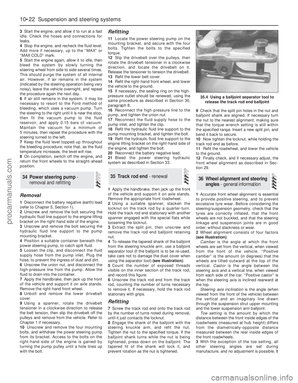
using the separator tool) (see illustration).
5Count the number of exposed threads
visible on the inner section of the track rod,
and record this figure.
6Unscrew the track rod end from the track
rod, counting the number of turns necessary
to remove it. If necessary, hold the track rod
stationary with grips.
Refitting
7Screw the track rod end onto the track rod
by the number of turns noted during removal,
until it just contacts the locknut.
8Engage the shank of the balljoint with the
steering knuckle arm, and refit the nut.
Tighten the nut to the specified torque. If the
balljoint shank turns while the nut is being
tightened, press down on the balljoint. The
tapered fit of the shank will lock it, and
prevent rotation as the nut is tightened.9Check that the split pin holes in the nut and
balljoint shank are aligned. If necessary turn
the nut to the nearest alignment, making sure
that the torque wrench setting is still within
the specified range. Insert a new split pin, and
bend it back to secure.
10Now tighten the locknut, while holding the
track rod end as before.
11Refit the roadwheel, and lower the vehicle
to the ground.
12Finally check, and if necessary adjust, the
front wheel alignment as described in Sec-
tion 29.
1Accurate front wheel alignment is essential
to provide positive steering, and to prevent
excessive tyre wear. Before considering the
steering/suspension geometry, check that the
tyres are correctly inflated, that the front
wheels are not buckled, and that the steering
linkage and suspension joints are in good
order, without slackness or wear.
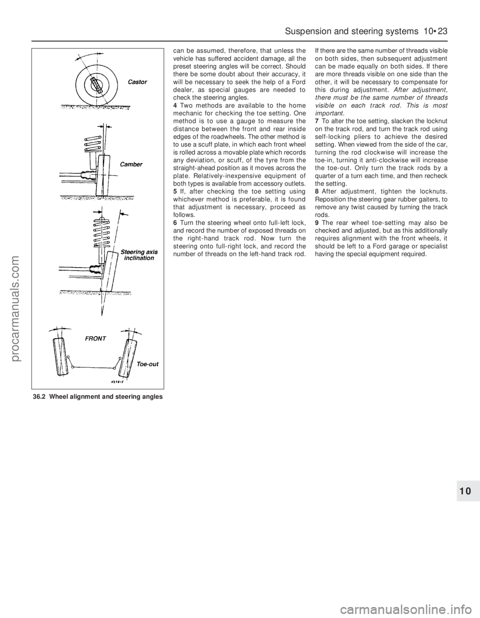
2Wheel alignment consists of four factors
(see illustration):
Camberis the angle at which the front
wheels are set from the vertical, when viewed
from the front of the vehicle. “Positive
camber” is the amount (in degrees) that the
wheels are tilted outward at the top of the
vertical. Castoris the angle between the
steering axis and a vertical line, when viewed
from each side of the car. “Positive castor” is
when the steering axis is inclined rearward at
the top.
Steering axis inclinationis the angle (when
viewed from the front of the vehicle) between
the vertical and an imaginary line drawn
through the suspension strut upper mounting
and the lower suspension arm balljoint.
Toe settingis the amount by which the
distance between the front inside edges of the
roadwheels (measured at hub height) differs
from the diametrically-opposite distance
measured between the rear inside edges of
the front roadwheels.
3With the exception of the toe setting, all
other steering angles are set during
manufacture, and no adjustment is possible. It
36 Wheel alignment and steering
angles - general information35 Track rod end - renewal34 Power steering pump -
removal and refitting
10•22 Suspension and steering systems
35.4 Using a balljoint separator tool to
release the track rod end balljoint
procarmanuals.com
Page 177 of 279
can be assumed, therefore, that unless the
vehicle has suffered accident damage, all the
preset steering angles will be correct. Should
there be some doubt about their accuracy, it
will be necessary to seek the help of a Ford
dealer, as special gauges are needed to
check the steering angles.
4Two methods are available to the home
mechanic for checking the toe setting. One
method is to use a gauge to measure the
distance between the front and rear inside
edges of the roadwheels. The other method is
to use a scuff plate, in which each front wheel
is rolled across a movable plate which records
any deviation, or scuff, of the tyre from the
straight-ahead position as it moves across the
plate. Relatively-inexpensive equipment of
both types is available from accessory outlets.
5If, after checking the toe setting using
whichever method is preferable, it is found
that adjustment is necessary, proceed as
follows.
6Turn the steering wheel onto full-left lock,
and record the number of exposed threads on
the right-hand track rod. Now turn the
steering onto full-right lock, and record the
number of threads on the left-hand track rod.If there are the same number of threads visible
on both sides, then subsequent adjustment
can be made equally on both sides. If there
are more threads visible on one side than the
other, it will be necessary to compensate for
this during adjustment. After adjustment,
there must be the same number of threads
visible on each track rod. This is most
important.
7To alter the toe setting, slacken the locknut
on the track rod, and turn the track rod using
self-locking pliers to achieve the desired
setting. When viewed from the side of the car,
turning the rod clockwise will increase the
toe-in, turning it anti-clockwise will increase
the toe-out. Only turn the track rods by a
quarter of a turn each time, and then recheck
the setting.
8After adjustment, tighten the locknuts.
Reposition the steering gear rubber gaiters, to
remove any twist caused by turning the track
rods.
9The rear wheel toe-setting may also be
checked and adjusted, but as this additionally
requires alignment with the front wheels, it
should be left to a Ford garage or specialist
having the special equipment required.
Suspension and steering systems 10•23
10
36.2 Wheel alignment and steering angles
procarmanuals.com
Page 269 of 279
6 Automatic transmission
REF•10Fault Finding
Note:Due to the complexity of the automatic transmission and its
electronic control system, it is difficult for the home mechanic to
properly diagnose and service this unit. For problems other than the
following, the vehicle should be taken to a dealer service department
or automatic transmission specialist.
Fluid leakage
m mAutomatic transmission fluid is usually deep red in colour. Fluid
leaks should not be confused with engine oil, which can easily be
blown onto the transmission by airflow.
m mTo determine the source of a leak, first remove all built-up dirt and
grime from the transmission housing and surrounding areas, using
a degreasing agent, or by steam-cleaning. Drive the vehicle at low
speed, so airflow will not blow the leak far from its source. Raise
and support the vehicle, and determine where the leak is coming
from. The following are common areas of leakage:
(a) Housing joints (Chapters 1 and 7, Part B).
(b) Dipstick tube (Chapters 1 and 7, Part B).
(c) Transmission-to-fluid cooler pipes/unions (Chapters 3 and 7,
Part B).
(d) Speedometer drive pinion O-ring (Chapter 7, Part B).
(e) Differential side gear oil seals (Chapter 7, Part B).
Transmission fluid brown, or has burned smell
m mTransmission fluid level low, or fluid in need of renewal (Chapter 1).
Transmission will not downshift (kickdown) with
accelerator pedal fully depressed
m mLow transmission fluid level (Chapter 1).
m mIncorrect selector cable adjustment (Chapter 7, Part B).
m mEngine management system fault (Chapters 1, 4, 5 and 6).
General gear selection problems
m
mChapter 7, Part B, deals with checking and adjusting the selector
cable on automatic transmissions. The following are common
problems which may be caused by a poorly-adjusted cable:
(a) Engine starting in gears other than Park or Neutral.
(b) Indicator on gear selector lever pointing to a gear other than the
one actually being used.
(c) Vehicle moves when in Park or Neutral.
(d) Poor gear shift quality or erratic gear changes.
Refer to Chapter 7, Part B for the selector cable adjustment
procedure.
Engine will not start in any gear, or starts in gears
other than Park or Neutral
m mIncorrect selector lever position sensor adjustment (Chapter 7,
Part B).
m mIncorrect selector cable adjustment (Chapter 7, Part B).
Transmission slips, shifts roughly, is noisy, or has no
drive in forward or reverse gears
m mThere are many probable causes for the above problems, but the
home mechanic should be concerned with only one possibility -
fluid level. Before taking the vehicle to a dealer or transmission
specialist, check the fluid level and condition of the fluid as
described in Chapter 1. Correct the fluid level as necessary, or
change the fluid if needed. If the problem persists, professional
help will be necessary.
7 Driveshafts
Clicking or knocking noise on turns (at slow speed
on full-lock)
m mLack of constant velocity joint lubricant (Chapter 8).
m mWorn outer constant velocity joint (Chapter 8).
Vibration when accelerating or decelerating
m
mWorn inner constant velocity joint (Chapter 8).
m mBent or distorted driveshaft (Chapter 8).
8 Braking system
Note:Before assuming that a brake problem exists, make sure that the tyres are in good condition and correctly inflated, that the front wheel
alignment is correct, and that the vehicle is not loaded with weight in an unequal manner. Apart from checking the condition of all pipe and hose
connections, any faults occurring on the Anti-lock Braking System (ABS) should be referred to a Ford dealer for diagnosis - the same applies to the
components of the Traction Control System (TCS).
Vehicle pulls to one side under braking
m mWorn, defective, damaged or contaminated front or rear brake
pads/shoes on one side (Chapter 1).
m mSeized or partially-seized front or rear brake caliper/wheel cylinder
piston (Chapter 9).
m mA mixture of brake pad/shoe lining materials fitted between sides
(Chapter 1).
m mBrake caliper mounting bolts loose (Chapter 9).
m mRear brake backplate mounting bolts loose (Chapter 9).
m mWorn or damaged steering or suspension components (Chap-
ter 10).
Noise (grinding or high-pitched squeal) when brakes
applied
m mBrake pad or shoe friction lining material worn down to metal
backing (Chapter 1).
m mExcessive corrosion of brake disc or drum (may be apparent after
the vehicle has been standing for some time) (Chapter 1).
m mForeign object (stone chipping, etc) trapped between brake disc
and splash shield (Chapter 1).
Excessive brake pedal travel
m mInoperative rear brake self-adjust mechanism (Chapter 9).
m mFaulty master cylinder (Chapter 9).
m mAir in hydraulic system (Chapter 9).
procarmanuals.com
Page 274 of 279
REF•15Glossary of Technical Terms
GGapThe distance the spark must travel in
jumping from the centre electrode to the side
electrode in a spark plug. Also refers to the
spacing between the points in a contact
breaker assembly in a conventional points-
type ignition, or to the distance between the
reluctor or rotor and the pickup coil in an
electronic ignition.
GasketAny thin, soft material - usually cork,
cardboard, asbestos or soft metal - installed
between two metal surfaces to ensure a good
seal. For instance, the cylinder head gasket
seals the joint between the block and the
cylinder head.
GaugeAn instrument panel display used to
monitor engine conditions. A gauge with a
movable pointer on a dial or a fixed scale is an
analogue gauge. A gauge with a numerical
readout is called a digital gauge.
HHalfshaftA rotating shaft that transmits
power from the final drive unit to a drive
wheel, usually when referring to a live rear
axle.
Harmonic balancerA device designed to
reduce torsion or twisting vibration in the
crankshaft. May be incorporated in the
crankshaft pulley. Also known as a vibration
damper.
HoneAn abrasive tool for correcting small
irregularities or differences in diameter in an
engine cylinder, brake cylinder, etc.
Hydraulic tappetA tappet that utilises
hydraulic pressure from the engine’s
lubrication system to maintain zero clearance
(constant contact with both camshaft and
valve stem). Automatically adjusts to variation
in valve stem length. Hydraulic tappets also
reduce valve noise.
IIgnition timingThe moment at which the
spark plug fires, usually expressed in the
number of crankshaft degrees before the
piston reaches the top of its stroke.
Inlet manifoldA tube or housing with
passages through which flows the air-fuel
mixture (carburettor vehicles and vehicles with
throttle body injection) or air only (port fuel-
injected vehicles) to the port openings in the
cylinder head.
JJump startStarting the engine of a vehicle
with a discharged or weak battery by
attaching jump leads from the weak battery to
a charged or helper battery.
LLoad Sensing Proportioning Valve (LSPV)A
brake hydraulic system control valve that
works like a proportioning valve, but also
takes into consideration the amount of weight
carried by the rear axle.
LocknutA nut used to lock an adjustment
nut, or other threaded component, in place.
For example, a locknut is employed to keep
the adjusting nut on the rocker arm in
position.
LockwasherA form of washer designed to
prevent an attaching nut from working loose.
MMacPherson strutA type of front
suspension system devised by Earle
MacPherson at Ford of England. In its original
form, a simple lateral link with the anti-roll bar
creates the lower control arm. A long strut - an
integral coil spring and shock absorber - is
mounted between the body and the steering
knuckle. Many modern so-called MacPherson
strut systems use a conventional lower A-arm
and don’t rely on the anti-roll bar for location.
MultimeterAn electrical test instrument with
the capability to measure voltage, current and
resistance.
NNOxOxides of Nitrogen. A common toxic
pollutant emitted by petrol and diesel engines
at higher temperatures.
OOhmThe unit of electrical resistance. One
volt applied to a resistance of one ohm will
produce a current of one amp.
OhmmeterAn instrument for measuring
electrical resistance.
O-ringA type of sealing ring made of a
special rubber-like material; in use, the O-ring
is compressed into a groove to provide the
sealing action.
Overhead cam (ohc) engineAn engine with
the camshaft(s) located on top of the cylinder
head(s).Overhead valve (ohv) engineAn engine with
the valves located in the cylinder head, but
with the camshaft located in the engine block.
Oxygen sensorA device installed in the
engine exhaust manifold, which senses the
oxygen content in the exhaust and converts
this information into an electric current. Also
called a Lambda sensor.
PPhillips screwA type of screw head having a
cross instead of a slot for a corresponding
type of screwdriver.
PlastigageA thin strip of plastic thread,
available in different sizes, used for measuring
clearances. For example, a strip of Plastigage
is laid across a bearing journal. The parts are
assembled and dismantled; the width of the
crushed strip indicates the clearance between
journal and bearing.
Propeller shaftThe long hollow tube with
universal joints at both ends that carries
power from the transmission to the differential
on front-engined rear wheel drive vehicles.
Proportioning valveA hydraulic control
valve which limits the amount of pressure to
the rear brakes during panic stops to prevent
wheel lock-up.
RRack-and-pinion steeringA steering system
with a pinion gear on the end of the steering
shaft that mates with a rack (think of a geared
wheel opened up and laid flat). When the
steering wheel is turned, the pinion turns,
moving the rack to the left or right. This
movement is transmitted through the track
rods to the steering arms at the wheels.
RadiatorA liquid-to-air heat transfer device
designed to reduce the temperature of the
coolant in an internal combustion engine
cooling system.
RefrigerantAny substance used as a heat
transfer agent in an air-conditioning system.
R-12 has been the principle refrigerant for
many years; recently, however, manufacturers
have begun using R-134a, a non-CFC
substance that is considered less harmful to
the ozone in the upper atmosphere.
Rocker armA lever arm that rocks on a shaft
or pivots on a stud. In an overhead valve
engine, the rocker arm converts the upward
movement of the pushrod into a downward
movement to open a valve.
Adjusting spark plug gap
Plastigage
Gasket
procarmanuals.com