Page 57 of 279

23If using Ford’s recommended procedure,
fit new oil seals to the camshafts as
described in paragraph 5 of Section 12.
24Using the marks and notes made on
dismantling to ensure that each is refitted to
its original camshaft, refit the toothed pulleys
to the camshafts, tightening the retaining
bolts loosely (see illustration). Slip the timing
belt back onto the pulleys (refer to para-
graph 21 of Section 10) and tighten the bolts
securely - use the forked holding tool
described in paragraph 18 of Section 10.
25The remainder of the reassembly
procedure, including checking the camshaft
alignment (valve timing) and setting the timing
belt tension, is as described in paragraphs 17
to 27 of Section 10.
Removal
Note:The following text assumes that the
cylinder head will be removed with both inlet
and exhaust manifolds attached; this
simplifies the procedure, but makes it a bulky
and heavy assembly to handle - an engine
hoist will be required, to prevent the risk of
injury, and to prevent damage to any delicate
components as the assembly is removed and
refitted. If it is wished first to remove the
manifolds, proceed as described in Sections
6 and 7 of this Chapter; amend the following
procedure accordingly.1Relieve the fuel system pressure (see
Chapter 4).
2With the vehicle parked on firm level
ground, open the bonnet and disconnect the
battery negative (earth) lead - see Chapter 5,
Section 1.
3Whenever you disconnect any vacuum
lines, coolant and emissions hoses, wiring
loom connectors, earth straps and fuel lines
as part of the following procedure, always
label them clearly, so that they can be
correctly reassembled.
4Unplugging the two electrical connectors,
disconnecting the vacuum hose (where fitted)
and disconnecting the crankcase breather
hose from the cylinder head cover, remove
the complete air cleaner assembly with the air
mass meter, the resonator and the plenum
chamber (see Chapter 4).
5Equalise the pressure in the fuel tank by
removing the filler cap, then undo the fuel
feed and return lines connecting the engine to
the chassis (see Chapter 4). Plug or cap all
open fittings.
6Disconnect the accelerator cable from the
throttle linkage as described in Chapter 4 -where fitted, disconnect also the cruise control
actuator cable (see Chapter 12). Secure the
cable(s) clear of the engine/transmission.
7Unbolt the power steering high-pressure
pipe from the cylinder head rear support
plate/engine lifting eye, and from the front
support plate/pump bracket. Releasing its
wire clip, unplug the power steering pressure
switch electrical connector, then unbolt the
earth lead from the cylinder head rear support
plate/engine lifting eye.
8Remove the three screws securing the
wiring “rail” to the rear of the manifold.
Releasing its wire clip, unplug the large
electrical connector (next to the fuel pressure
regulator) to disconnect the engine wiring from
the main loom (see illustration). Unplug the
electrical connectors on each side of the
ignition coil, and the single connector from
beneath the front of the thermostat housing, to
disconnect the coil and coolant temperature
gauge sender wiring (see illustration).
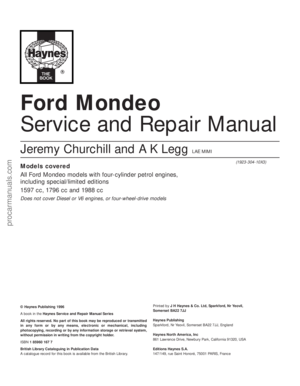
9Marking or labelling them as they are
unplugged, disconnect the vacuum hoses as
follows:
(a) One from the rear of the throttle housing
(only the one hose - there is no need to
disconnect the second hose running to
the fuel pressure regulator).
(b) One from the union on the inlet manifold’s
left-hand end (see illustration).
(c) The braking system vacuum servo unit
hose (see Chapter 9 for details).
(d) Disconnect all vacuum hoses from the
Exhaust Gas Recirculation system
components - one from the EGR valve
and two from the EGR pipe. (Note that
these last two are of different sizes, as are
their pipe stubs, so that they can only be
connected the correct way round.)
10Unbolt both parts of the exhaust manifold
heat shield; unclip the coolant hose to allow the
upper part to be withdrawn. Either remove the
dipstick and tube, or swing them out of the way.
11Unscrew the single bolt securing the
pulse-air filter housing to the engine/
transmission front mounting bracket, then
disconnect its vacuum hose.
12Drain the cooling system (see Chapter 1).
13Disconnect all coolant hoses from the
thermostat housing (see illustration).
14 Cylinder head -
removal and refitting
In-car engine repair procedures 2A•17
2A
14.9 Disconnect vacuum hoses (arrowed)
as described in text14.13 Disconnect all coolant hoses
(arrowed) from thermostat housing
13.24 . . . while camshaft toothed pulleys
are refitted14.8A Release wire clip to unplug engine
wiring loom connector from inlet manifold14.8B Unplug connectors (arrowed) to
disconnect ignition coil wiring
Masking tape and/or a touch-
up paint applicator work
well for marking items.
Take instant photos, or
sketch the locations of components
and brackets.
procarmanuals.com
Page 58 of 279
; disconnect the oxygen
sensor wiring, so that it is not strained by the
weight of the exhaust syste")
14Unscrew the two nuts to disconnect the
exhaust system front downpipe from the
manifold (Chapter 4); disconnect the oxygen
sensor wiring, so that it is not strained by the
weight of the exhaust system.
15Remove the auxiliary drivebelt (see
Chapter 1).
16Support the weight of the
engine/transmission using a trolley jack, with
a wooden spacer to prevent damage to the
sump.
17Unscrew the six nuts securing the
engine/transmission right-hand mounting
bracket, then withdraw the bracket. Unbolt
the auxiliary drivebelt’s idler pulley (see
illustration).
18Unbolt the cylinder head front and rear
support plates (see illustrations).
19Remove the timing belt and both
camshafts (see Sections 10 and 13); if the
cylinder head is to be dismantled, withdraw
the hydraulic tappets.
20Remove the timing belt inner shield (see
Section 9).
21Working in the reverseof the sequence
shown in illustration 14.32C, slacken the ten
cylinder head bolts progressively and by one
turn at a time; a Torx key (TX 55 size) will be
required. Remove each bolt in turn, and
ensure that new replacements are obtained
for reassembly; these bolts are subjected to
severe stresses and so must be renewed,
regardless of their apparent condition,
whenever they are disturbed.22Lift the cylinder head away; use
assistance if possible, as it is a heavy
assembly (see illustration). Remove the
gasket, noting the two dowels, and discard it.
Refitting
23The mating faces of the cylinder head and
cylinder block must be perfectly clean before
refitting the head. Use a hard plastic or wood
scraper to remove all traces of gasket and
carbon; also clean the piston crowns. Take
particular care, as the soft aluminium alloy is
easily damaged. Also, make sure that the
carbon is not allowed to enter the oil and
water passages - this is particularly important
for the lubrication system, as carbon could
block the oil supply to any of the engine’s
components. Using adhesive tape and paper,
seal the water, oil and bolt holes in the
cylinder block. Clean all the pistons in the
same way.24Check the mating surfaces of the cylinder
block and the cylinder head for nicks, deep
scratches and other damage. If slight, they
may be removed carefully with a file, but if
excessive, machining may be the only
alternative to renewal.
25If warpage of the cylinder head gasket
surface is suspected, use a straight edge to
check it for distortion. Refer to Part B of this
Chapter, Section 7, if necessary.
26Wipe clean the mating surfaces of the
cylinder head and cylinder block. Check that
the two locating dowels are in position in the
cylinder block, and that all cylinder head bolt
holes are free from oil.
27Position a new gasket over the dowels on
the cylinder block surface, so that the
“TOP/OBEN” mark is uppermost, and the
tooth (or teeth, according to engine size)
protruding from one edge point to the front of
the vehicle (see illustration).
28Temporarily refit the crankshaft pulley,
and rotate the crankshaft anti-clockwise so
that No 1 cylinder’s piston is lowered to
approximately 20 mm before TDC, thus
avoiding any risk of valve/piston contact and
damage during reassembly.
29As the cylinder head is such a heavy and
awkward assembly to refit with manifolds, it is
helpful to make up a pair of guide studs from
two 10 mm (thread size) studs approximately
90 mm long, with a screwdriver slot cut in one
end - two old cylinder head bolts with their
heads cut off would make a good starting
point. Screw these guide studs, screwdriver
slot upwards to permit removal, into the bolt
holes at diagonally-opposite corners of the
cylinder block surface (or into those where
the locating dowels are fitted, as shown);
ensure that approximately 70 mm of stud
protrudes above the gasket.
30Refit the cylinder head, sliding it down the
guide studs (if used) and locating it on the
dowels (see illustration). Unscrew the guide
studs (if used) when the head is in place.
31Fit the new cylinder head bolts dry (do not
oiltheir threads); carefully enter each into its
hole and screw it in, by hand only, until finger-
tight.
32Working progressively and in the
sequence shown, use first a torque wrench,
2A•18 In-car engine repair procedures
14.17 Unbolt auxiliary drivebelt idler pulley14 18A Remove cylinder head front . . .14.18B . . . and rear support plates
14.22 Using an engine hoist to lift off the
cylinder head complete with manifolds
14.27 Ensuring protruding tooth (or teeth)
“A” are at front and marking “B” is
upwards, locate new cylinder head gasket
on dowels “C”
To prevent carbon entering
the gap between the pistons
and bores, smear a little
grease in the gap. After
cleaning each piston, use a small brush
to remove all traces of grease and
carbon from the gap, then wipe away
the remainder with a clean rag.
procarmanuals.com
Page 59 of 279
.
Note:Once tightened")
then an ordinary socket extension bar and an
angle gauge, to tighten the cylinder head
bolts in the stages given in the Specifications
Section of this Chapter (see illustrations).
Note:Once tightened correctly, following this
procedure, the cylinder head bolts do not
require check-tightening, and must notbe re-
torqued.
33Refit the hydraulic tappets (if removed),
the camshafts, their oil seals and pulleys (see
Sections 10, 11, 12 and 13, as appropriate).
Temporarily refit the crankshaft pulley, and
rotate the crankshaft clockwise to return the
pulley notches to the position described in
paragraph 8 of Section 10.
34Refit the timing belt and covers, checking
the camshaft alignment (valve timing) and
setting the timing belt tension, as described in
Section 10.
35The remainder of reassembly is the
reverse of the removal procedure, noting the
following points:
(a) Tighten all fasteners to the torque wrench
settings specified.
(b) When reassembling the
engine/transmission right-hand mounting,
renew the self-locking nuts, and do not
allow the mounting to twist as the middle
two of the bracket’s six nuts are
tightened.
(c) Refill the cooling system, and top-up the
engine oil.
(d) Check all disturbed joints for signs of oil
or coolant leakage, once the engine has
been restarted and warmed-up to normal
operating temperature.
Removal
Note:To carry out this task with the
engine/transmission installed in the vehicle
requires the assistance of at least one person,
plus the equipment necessary to raise and
support the front of the vehicle (high enough
that the sump can be withdrawn from
underneath), and to lift and support the
complete engine/transmission unit 2 to 3 inches from its mountings while the vehicle
is raised. Precise details of the procedure will
depend on the equipment available - the
following is typical.
The full procedure outlined below must be
followed, so that the mating surfaces can be
cleaned and prepared to achieve an oil-tight
joint on reassembly, and so that the sump
can be aligned correctly; depending on your
skill and experience, and the tools and
facilities available, it may be that this task can
be carried out only with the engine removed
from the vehicle.
Note that the sump gasket must be
renewed whenever it is disturbed.
1With the vehicle parked on firm level
ground, open the bonnet and disconnect the
battery negative (earth) lead - see Chapter 5,
Section 1.
2Drain the engine oil, then clean and refit the
engine oil drain plug, tightening it to the
specified torque wrench setting. Although not
strictly necessary as part of the dismantling
procedure, owners are advised to remove
and discard the oil filter, so that it can be
renewed with the oil (see Chapter 1).
3Drain the cooling system (see Chapter 1).
4Disconnect the radiator bottom hose from
the radiator union and from the (heater)
coolant pipe. Unbolt the coolant pipe from
the sump; if they will prevent sump removal,
disconnect or release the coolant hoses from
the oil cooler unions (where fitted).
5Unscrew the two bolts securing the powersteering system pipes to the right-hand side
of the subframe.
6Unplug the electrical connector(s) to
disconnect the oxygen sensor and, where
fitted, the oil level sensor wiring - unclip the
connectors to release the wiring where
necessary.
7Where the vehicle is fitted with automatic
transmission, trace the fluid cooler lines from
the transmission to the radiator, and release
them from any clips etc, so that they have as
much movement as possible.
8Remove the auxiliary drivebelt cover (see
Chapter 1).
9Unscrew the nuts to disconnect the
exhaust system front downpipe from the
manifold, then either unhook all the system’s
rubber mountings and withdraw the complete
exhaust system from under the vehicle, or
remove only the downpipe/catalytic converter
(see Chapter 4 for details).
10Unscrew the sump-to-transmission bolts,
also any securing the engine/transmission
lower adaptor plate.
11Unplugging the two electrical connectors,
disconnecting the vacuum hose (where fitted)
and disconnecting the crankcase breather
hose from the cylinder head cover, remove
the complete air cleaner assembly with the air
mass meter, the resonator and the plenum
chamber (see Chapter 4).
12Take the weight of the engine/
transmission unit using the lifting eyes
provided on the cylinder head; bolt on
15 Sump - removal and refitting
In-car engine repair procedures 2A•19
2A
14.32B . . . and to third stage using angle
gauge14.32C Cylinder head bolt tightening
sequence
Note:View from rear of vehicle15.12 Equipment must be available to raise
and support engine/transmission unit while
vehicle is raised, to allow sump removal
14.30 Refitting cylinder head - note
fabricated guide studs (arrowed)14.32A Tightening cylinder head bolts (to
first and second stages) using torque
wrench . . .
procarmanuals.com
Page 60 of 279
. Remove completely the
engine/transmission front mounting, unscrew
the rear mounting’s centre bolt, and unbolt
the left-hand mounting from t")
additional lifting eyes where required (see
illustration). Remove completely the
engine/transmission front mounting, unscrew
the rear mounting’s centre bolt, and unbolt
the left-hand mounting from the body.
Unscrew the six nuts securing the right-hand
mounting bracket, and withdraw the bracket.
13Being careful to watch the wiring, coolant
hoses, fluid cooler pipes or gearchange
linkage and transmission support rods (where
appropriate), and the radiator electric cooling
fan, to ensure that nothing is trapped,
stretched or damaged, lift the
engine/transmission unit by 2 to 3 inches and
support it securely.
14Progressively unscrew the sump retaining
bolts. Break the joint by striking the sump
with the palm of the hand, then lower the
sump and withdraw it with the
engine/transmission lower adaptor plate; note
the presence of any shims between the sump
and transmission.
15Remove and discard the sump gasket;
this must be renewed as a matter of course
whenever it is disturbed.
16While the sump is removed, take the
opportunity to remove the oil pump pick-up/
strainer pipe and to clean it (see Section 16).
Refitting
17On reassembly, thoroughly clean and
degrease the mating surfaces of the cylinder
block/crankcase and sump, then use a cleanrag to wipe out the sump and the engine’s
interior. If the oil pump pick-up/strainer pipe
was removed, fit a new gasket and refit the
pipe, tightening its screws to the specified
torque wrench setting. Fit the new gasket to
the sump mating surface so that the gasket
fits into the sump groove (see illustration).
18If the sump is being refitted with the
engine/transmission still connected and in the
vehicle, proceed as follows:
(a) Check that the mating surfaces of the
sump, the cylinder block/crankcase and
the transmission are absolutely clean and
flat. Any shims found on removal of the
sump must be refitted in their original
locations.
(b) Apply a thin film of suitable sealant (Ford
recommend Hylosil 102) to the junctions
of the cylinder block/crankcase with the
oil pump and the crankshaft left-hand oil
seal carrier. Without delay - the sump
bolts must be fully tightened within 10 to
20 minutes of applying the sealant - offer
up the sump and engine/transmission
lower adaptor plate, and refit the bolts,
tightening them lightly at first (see
illustration).
(c) Ensuring that the engine/transmission
lower adaptor plate is correctly located,
firmly press the sump against the
transmission, and tighten the
transmission-to-sump (ie, engine) bolts to
the specified torque wrench setting.(d) Without disturbing the position of the
sump, and working in a diagonal
sequence from the centre outwards,
tighten the sump bolts to the specified
torque wrench setting.
(e) Proceed to paragraph 20.
19If the sump is being refitted with the
engine and transmission separated (in or out
of the vehicle), proceed as follows:
(a) Apply a thin film of suitable sealant (Ford
recommend Hylosil 102) to the junctions
of the cylinder block/crankcase with the
oil pump and the crankshaft left-hand oil
seal carrier (see illustration). Without
delay - the sump bolts must be fully
tightened within 10 to 20 minutes of
applying the sealant - offer up the sump
to the cylinder block/crankcase, and
insert the sump bolts, tightening them
lightly at first.
(b) Using a suitable straight edge to check
alignment across the flat-machined faces
of each, move the sump as necessary so
that its left-hand face - including any
shims found on removal - is flush with
that of the cylinder block/crankcase (see
illustration). Without disturbing the
position of the sump, and working in a
diagonal sequence from the centre
outwards, tighten the sump bolts to the
specified torque wrench setting.
(c) Check again that both faces are flush
before proceeding; if necessary, unbolt
the sump again, clean the mating
surfaces, and repeat the full procedure to
ensure that the sump is correctly aligned.
(d) If it is not possible to achieve exact
alignment by moving the sump, shims are
available in thicknesses of 0.25 mm
(colour-coded yellow) or 0.50 mm (colour-
coded black) to eliminate the discrepancy
(see illustration).
20The remainder of reassembly is the
reverse of the removal procedure, noting the
following points.
(a) Tighten all fasteners to the torque wrench
settings specified.
(b) Always renew any self-locking nuts
disturbed on removal.
(c) Lower the engine/transmission unit into
place, and reassemble the rear, left-hand
2A•20 In-car engine repair procedures
15.17 Ensure gasket is located correctly in
sump groove15.18 Engine/transmission lower adaptor
plate (arrowed) must be refitted with sump15.19A Apply sealant (arrowed) as
directed when refitting sump
15.19B Checking alignment of sump with
cylinder block/crankcase15.19C Sump-to-cylinder block/crankcase
alignment shims
1 Fitting points on sump 2 Shim
procarmanuals.com
Page 61 of 279
 Fitting the Ford service tool")
and right-hand mountings. Do not yet
release the hoist; the weight of the
engine/transmission unit must not be
taken by the mountings until all are
correctly aligned.
(d) Fitting the Ford service tool in place of the
front mounting, tighten the
engine/transmission mounting fasteners
to their specified torque wrench settings,
and in the sequence described in Part B
of this Chapter, Section 4, paragraphs 49
and 50.
(e) Refill the cooling system (see Chapter 1).
(f) Refill the engine with oil, remembering
that you are advised to fit a new filter (see
Chapter 1).
(g) Check for signs of oil or coolant leaks
once the engine has been restarted and
warmed-up to normal operating
temperature.
Removal
Note:While this task is theoretically possible
when the engine is in place in the vehicle, in
practice, it requires so much preliminary
dismantling, and is so difficult to carry out due
to the restricted access, that owners are
advised to remove the engine from the vehicle
first. Note, however, that the oil pumppressure relief valve can be removed with the
engine in situ - see paragraph 8.
In addition to the new pump gasket and
other replacement parts required, read
through Section 15, and ensure that the
necessary tools and facilities are available.
1Remove the timing belt (see Section 10).
2Withdraw the crankshaft toothed pulley
and the thrustwasher behind it, noting which
way round the thrustwasher is fitted (see
Section 11).
3Remove the sump (see Section 15).
4Undo the screws securing the oil pump
pick-up/strainer pipe to the pump, then
unscrew the nut and withdraw the oil pump
pick-up/strainer pipe. Discard the gasket.
5Unbolt the pump from the cylinder
block/crankcase (see illustration). Withdraw
and discard the gasket, and remove the
crankshaft right-hand oil seal. Thoroughly
clean and degrease all components,
particularly the mating surfaces of the pump,
the sump, and the cylinder block/crankcase.
Inspection
6Unscrew the Torx screws, and remove the
pump cover plate; noting any identification
marks on the rotors, withdraw the rotors (see
illustration).
7Inspect the rotors for obvious signs of wear
or damage, and renew if necessary; if either
rotor, the pump body, or its cover plate are
scored or damaged, the complete oil pump
assembly must be renewed.
8The oil pressure relief valve can bedismantled, if required, without disturbing the
pump. With the vehicle parked on firm level
ground, apply the handbrake securely and
raise its front end, supporting it securely on
axle stands. Remove the front right-hand
roadwheel and auxiliary drivebelt cover (see
Chapter 1) to provide access to the valve.
9Unscrew the threaded plug, and recover
the valve spring and plunger (see
illustrations). If the plug’s sealing O-ring is
worn or damaged, a new one must be
obtained, to be fitted on reassembly.
10Reassembly is the reverse of the
dismantling procedure; ensure the spring and
valve are refitted the correct way round, and
tighten the threaded plug securely.
Refitting
11The oil pump must be primed on
installation, by pouring clean engine oil into it,
and rotating its inner rotor a few turns.
12Using grease to stick the new gasket in
place on the cylinder block/crankcase, and
rotating the pump’s inner rotor to align with
the flats on the crankshaft, refit the pump and
insert the bolts, tightening them lightly at first
(see illustration).
13Using a suitable straight edge and feeler
gauges, check that the pump is both centred
exactlyaround the crankshaft, and aligned
squarely so that its (sump) mating surface is
exactly the same amount - between 0.3 and
0.8 mm - below that of the cylinder block/
crankcase on each side of the crankshaft
(see illustration). Being careful not to disturb
16 Oil pump - removal,
inspection and refitting
In-car engine repair procedures 2A•21
2A
16.9B . . . to withdraw oil pressure relief
valve spring and plunger16.12 Use new gasket when refitting oil
pump16.13 Check the oil pump is positioned
correctly
16.5 Unscrew bolts (arrowed) to remove
oil pump16.6 Withdrawing oil pump inner rotor16.9A Unscrew threaded plug - seen
through right-hand wheel arch . . .
procarmanuals.com
Page 62 of 279

the gasket, move the pump into the correct
position, and tighten its bolts to the specified
torque wrench setting.
14Check that the pump is correctly located;
if necessary, unbolt it again, and repeat the
full procedure to ensure that the pump is
correctly aligned.
15Fit a new crankshaft right-hand oil seal
(see Section 20).
16Using grease to stick the gasket in place
on the pump, refit the pick-up/strainer pipe,
tightening its screws and nut to their specified
torque wrench settings (see illustration).
17The remainder of reassembly is the
reverse of the removal procedure, referring to
the relevant text for details where required.
1Drain the cooling system (see Chapter 1).
Disconnect the coolant hoses from the oil
cooler.
2Unscrew the oil filter (see Chapter 1) -
catch any escaping oil in a drip tray.
3Unscrew the filter adaptor from the oil
pump, and withdraw the oil cooler; note how
its unions are aligned, and be prepared for oil
loss from the cooler.
4Refitting is the reverse of the removal
procedure, noting the following points:(a) Renew all O-rings and seals disturbed on
removal.
(b) Align the cooler’s unions as noted on
removal, and tighten the adaptor to the
specified torque wrench setting.
(c) Refill the cooling system (see Chapter 1).
(d) Refit the oil filter, then check the engine
oil level, and top-up as necessary (see
Chapter 1).
(e) Check for signs of oil or coolant leaks once
the engine has been restarted and warmed-
up to normal operating temperature.
1With the vehicle parked on firm level
ground, open the bonnet and disconnect the
battery negative (earth) lead - see Chapter 5,
Section 1.
2Raise the front of the vehicle, and support it
securely on axle stands.
3Undo the two screws, and remove the
sensor’s cover from the front of the sump
(see illustration).
4Unplug the wiring from the sensor (see
illustration). Where necessary, unplug the
electrical connector to disconnect the sensor
wiring, and unclip the connector to release
the wiring from the vehicle.
5Unscrew the sensor, and quickly plug the
sump aperture to minimise oil loss; note the
sensor’s seal.6Refitting is the reverse of the removal
procedure; renew the sensor’s seal if it is
worn or damaged, and tighten the sensor to
the specified torque wrench setting. Check
the engine oil level, and top-up as necessary
(see Chapter 1) - check for signs of oil leaks
once the engine has been restarted and
warmed-up to normal operating temperature.
1The switch is screwed into the rear of the
cylinder block, above the right-hand
driveshaft’s support bearing (see
illustration).
2With the vehicle parked on firm level
ground, open the bonnet and disconnect the
battery negative (earth) lead - see Chapter 5,
Section 1.
3Raise the front of the vehicle, and support it
securely on axle stands.
4Unplug the wiring from the switch, and
unscrew it; be prepared for some oil loss.
5Refitting is the reverse of the removal
procedure; apply a thin smear of suitable
sealant to the switch threads, and tighten it to
the specified torque wrench setting. Check
the engine oil level, and top-up as necessary
(see Chapter 1). Check for signs of oil leaks
once the engine has been restarted and
warmed-up to normal operating temperature.
Note:Don’t try to prise these seals out
without removing the oil pump or seal carrier -
the seals are too soft, and the amount of
space available is too small, for this to be
possible without considerable risk of damage
to the seal housing and/or the crankshaft
journal. Follow exactly the procedure given
below.
Right-hand seal
1Remove the oil pump (see Section 16).
2Drive the oil seal out of the pump from
behind (see illustration).
20 Crankshaft oil seals -
renewal
19 Oil pressure warning light
switch - removal and refitting
18 Oil level sensor-
removal and refitting
17 Oil cooler -
removal and refitting
2A•22 In-car engine repair procedures
16.16 Use new gasket when refitting oil
pick-up pipe to pump18.3 Remove screws (arrowed) to remove
oil level sensor cover . . .18.4 . . . disconnecting wiring from sensor
19.1 Oil pressure warning light switch
(arrowed) is screwed into rear of cylinder
block, above right-hand driveshaft support
bearing
20.2 Driving out crankshaft right-hand oil
seal
procarmanuals.com
Page 63 of 279
. Grease
the lips and pe")
3Clean the seal housing and crankshaft,
polishing off any burrs or raised edges, which
may have caused the seal to fail in the first
place.
4Refit the oil pump (see Section 16). Grease
the lips and periphery of the new seal, to ease
installation.
5To fit a new seal, Ford recommend the use
of their service tool 21-093A, with the
crankshaft pulley bolt, to draw the seal into
place; an alternative can be arranged using a
socket of suitable size, with a washer to
match the crankshaft pulley bolt (see
illustration).
6If such tools are not available, press the
seal squarely into place by hand; tap it in until
it is flush with the pump housing, using a soft-
faced mallet and a socket with an outside
diameter only slightly smaller than the seal’s
(see illustration). This approach requires
great care, to ensure that the seal is fitted
squarely, without distortion or damage.
7Wash off any traces of oil. The remainder of
reassembly is the reverse of the removal
procedure, referring to the relevant text for
details where required. Check for signs of oil
leakage when the engine is restarted.
Left-hand seal
8Remove the transmission (see the relevant
Part of Chapter 7).
9Where appropriate, remove the clutch
(Chapter 8).
10Unbolt the flywheel/driveplate (see
Section 21).11Remove the sump (see Section 15).
12Unbolt the oil seal carrier (see
illustration). Remove and discard its gasket.
13Supporting the carrier evenly on wooden
blocks, drive the oil seal out of the carrier
from behind (see illustration).
14Clean the seal housing and crankshaft,
polishing off any burrs or raised edges, which
may have caused the seal to fail in the first
place. Clean also the mating surfaces of the
cylinder block/crankcase and carrier, using a
scraper to remove all traces of the old gasket
- be careful not to scratch or damage the
material of either - then use a suitable solvent
to degrease them.
15Use grease to stick the new gasket in
place on the cylinder block/crankcase, then
offer up the carrier (see illustration).
16Using a suitable straight edge and feeler
gauges, check that the carrier is both centred
exactlyaround the crankshaft, and aligned
squarely so that its (sump) mating surface is
exactly the same amount - between 0.3 and
0.8 mm - below that of the cylinder
block/crankcase on each side of the
crankshaft. Being careful not to disturb the
gasket, move the carrier into the correct
position, and tighten its bolts to the specified
torque wrench setting (see illustration).
17Check that the carrier is correctly located;
if necessary, unbolt it again, and repeat the
full procedure to ensure that the carrier is
correctly aligned.
18Ford’s recommended method of seal
fitting is to use service tool 21-141, with twoflywheel bolts to draw the seal into place. If
this is not available, make up a guide from a
thin sheet of plastic or similar, lubricate the
lips of the new seal and the crankshaft
shoulder with grease, then offer up the seal,
with the guide feeding the seal’s lips over the
crankshaft shoulder (see illustration). Press
the seal evenly into its housing by hand only,
and use a soft-faced mallet gently to tap it
into place until it is flush with the surrounding
housing.
19Wipe off any surplus oil or grease; the
remainder of the reassembly procedure is the
reverse of dismantling, referring to the
relevant text for details where required.
Check for signs of oil leakage when the
engine is restarted.
In-car engine repair procedures 2A•23
2A
20.15 Use new gasket when refitting left-
hand oil seal carrier20.16 Check the oil seal carrier is correctly
positioned20.18 Using guide made from thin sheet of
plastic to slide oil seal lips over crankshaft
shoulder
20.5 Socket of correct size can be used to
replace Ford service tool, drawing new
seal into place as described20.6 If seal is tapped into place as shown,
exercise great care to prevent seal from
being damaged or distorted20.12 Unscrew bolts (arrowed) to remove
crankshaft left-hand oil seal carrier . . .
20.13 . . . and ensure that carrier is
properly supported when driving out used
oil seal - note notches provided in carrier
for drift
procarmanuals.com
Page 64 of 279
. Now is a good time to
check components such as oil seals and
renew them if necessary.
2Where appropriate, remove the clutch
(Chap")
Removal
1Remove the transmission (see the relevant
Part of Chapter 7). Now is a good time to
check components such as oil seals and
renew them if necessary.
2Where appropriate, remove the clutch
(Chapter 8). Now is a good time to check or
renew the clutch components and pilot
bearing.
3Use a centre-punch or paint to make
alignment marks on the flywheel/driveplate
and crankshaft, to ensure correct alignment
during refitting.
4Prevent the flywheel/driveplate from
turning by locking the ring gear teeth, or by
bolting a strap between the flywheel/
driveplate and the cylinder block/
crankcase. Slacken the bolts evenly until all
are free.
5Remove each bolt in turn, and ensure that
new replacements are obtained for
reassembly; these bolts are subjected to
severe stresses, and so must be renewed,
regardless of their apparent condition,
whenever they are disturbed.
6Noting the reinforcing plate (automatic
transmission-equipped models only),
withdraw the flywheel/driveplate; do not drop
it - it is very heavy.
Inspection
7Clean the flywheel/driveplate to remove
grease and oil. Inspect the surface for cracks,
rivet grooves, burned areas and score marks.
Light scoring can be removed with emery
cloth. Check for cracked and broken ring gear
teeth. Lay the flywheel/driveplate on a flat
surface, and use a straight edge to check for
warpage.
8Clean and inspect the mating surfaces of
the flywheel/driveplate and the crankshaft. If
the crankshaft left-hand seal is leaking, renew
it (see Section 20) before refitting the
flywheel/driveplate.
9While the flywheel/driveplate is removed,clean carefully its inboard (right-hand) face,
particularly the recesses which serve as the
reference points for the crankshaft
speed/position sensor. Clean the sensor’s tip,
and check that the sensor is securely
fastened.
Refitting
10On refitting, ensure that the
engine/transmission adaptor plate is in place
(where necessary), then fit the
flywheel/driveplate to the crankshaft so that
all bolt holes align - it will fit only one way -
check this using the marks made on removal.
Do not forget the reinforcing plate (where
fitted).
11Lock the flywheel/driveplate by the
method used on dismantling. Working in a
diagonal sequence to tighten them evenly,
and increasing to the final amount in two or
three stages, tighten the new bolts to the
specified torque wrench setting (see
illustration).
12The remainder of reassembly is the
reverse of the removal procedure, referring to
the relevant text for details where required.
General
1The engine/transmission mountings
seldom require attention, but broken or
deteriorated mountings should be renewed
immediately, or the added strain placed on
the driveline components may cause damage
or wear.
2While separate mountings may be removed
and refitted individually, if more than one is
disturbed at a time - such as if theengine/transmission unit is removed from its
mountings - they must be reassembled and
their fasteners tightened in a strict sequence.
3On reassembly, the weight of the
engine/transmission unit must not be taken
by the mountings until all are correctly
aligned. Fitting the Ford service tool in place
of the front mounting, tighten the
engine/transmission mounting fasteners to
their specified torque wrench settings, and in
the sequence described in Part B of this
Chapter, Section 4, paragraphs 49 and 50.
Inspection
4During the check, the engine/transmission
unit must be raised slightly, to remove its
weight from the mountings.
5Raise the front of the vehicle, and support it
securely on axle stands. Position a jack under
the sump, with a large block of wood
between the jack head and the sump, then
carefully raise the engine/transmission just
enough to take the weight off the mountings.
Warning: DO NOT place any part
of your body under the engine
when it is supported only by a
jack!
6Check the mountings to see if the rubber is
cracked, hardened or separated from the
metal components. Sometimes the rubber
will split right down the centre.
7Check for relative movement between each
mounting’s brackets and the engine/
transmission or body (use a large screwdriver
or lever to attempt to move the mountings). If
movement is noted, lower the engine and
check-tighten the mounting fasteners.
Renewal
Front mounting
8Unbolt the resonator support bracket from
the engine compartment front crossmember,
slacken the two clamp screws securing the
22 Engine/transmission
mountings -
inspection and renewal
21 Flywheel/driveplate -
removal, inspection and refitting
2A•24 In-car engine repair procedures
21.11 Note method used to lock
flywheel/driveplate while (new) bolts are
tightened
22.8 Engine/transmission front mounting - manual transmission shown, automatic
equivalent similar
1 Transmission 3 Mounting 5 Mounting centre bolt
2 Mounting bracket 4 Front suspension subframe
procarmanuals.com
 1
1 2
2 3
3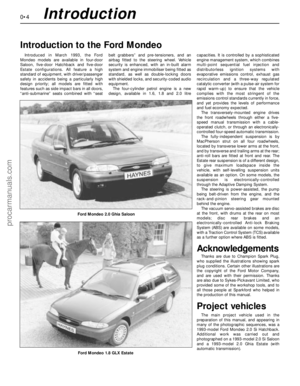 4
4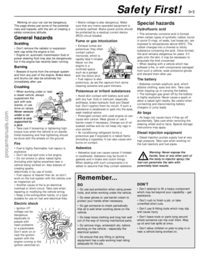 5
5 6
6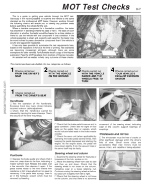 7
7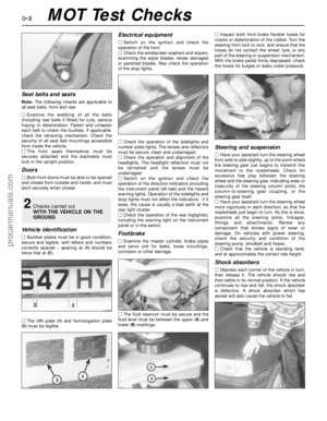 8
8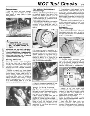 9
9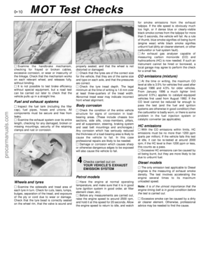 10
10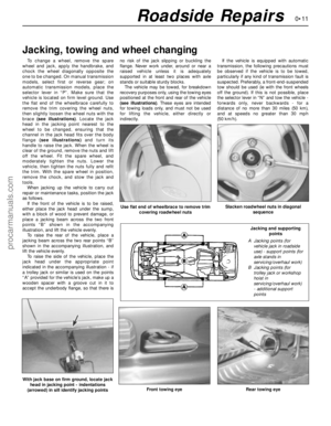 11
11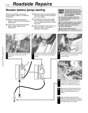 12
12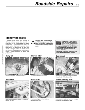 13
13 14
14 15
15 16
16 17
17 18
18 19
19 20
20 21
21 22
22 23
23 24
24 25
25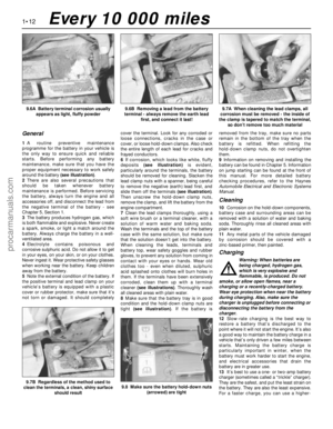 26
26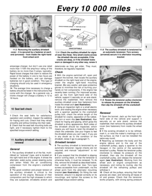 27
27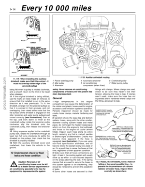 28
28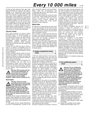 29
29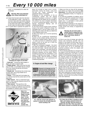 30
30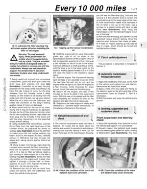 31
31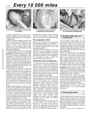 32
32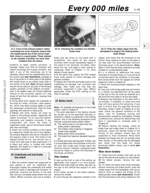 33
33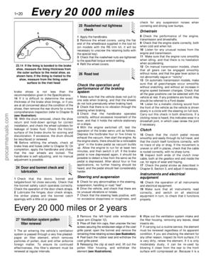 34
34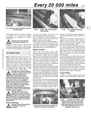 35
35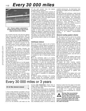 36
36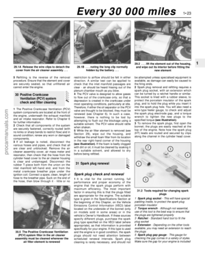 37
37 38
38 39
39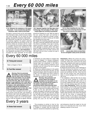 40
40 41
41 42
42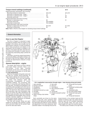 43
43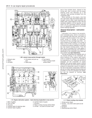 44
44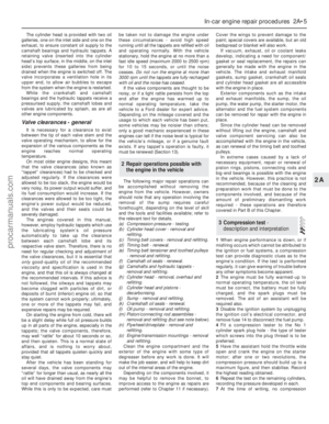 45
45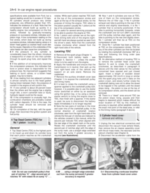 46
46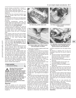 47
47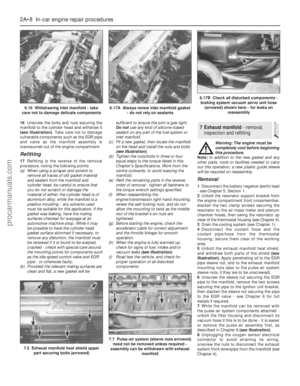 48
48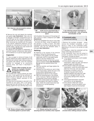 49
49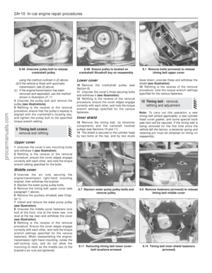 50
50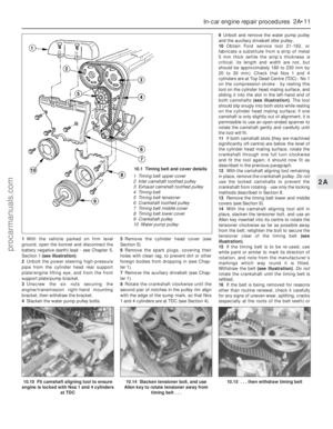 51
51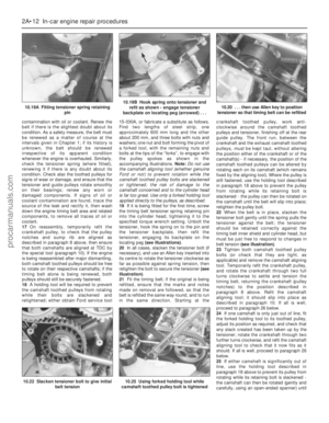 52
52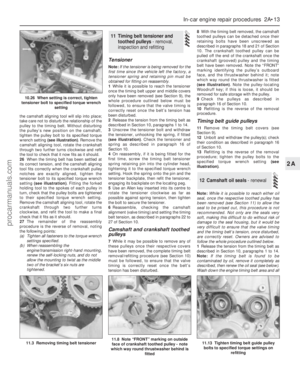 53
53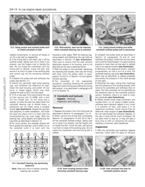 54
54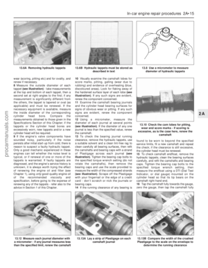 55
55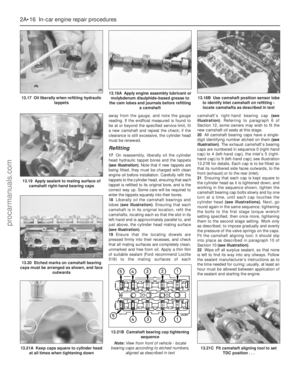 56
56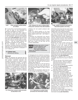 57
57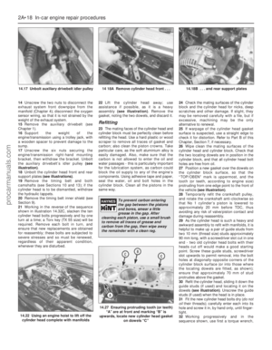 58
58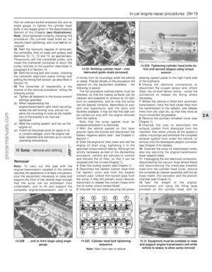 59
59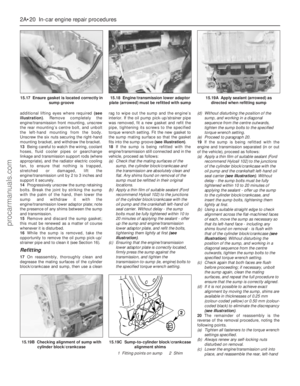 60
60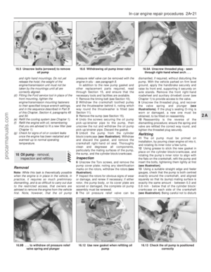 61
61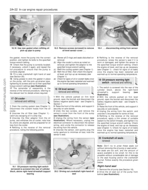 62
62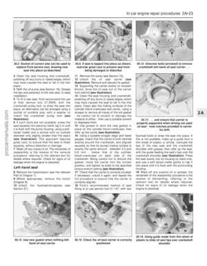 63
63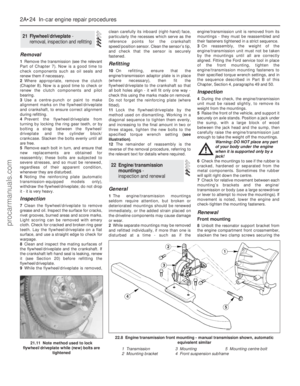 64
64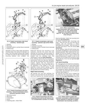 65
65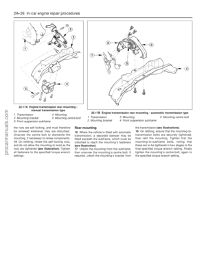 66
66 67
67 68
68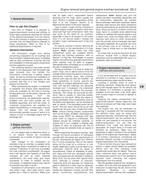 69
69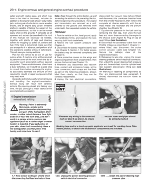 70
70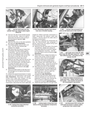 71
71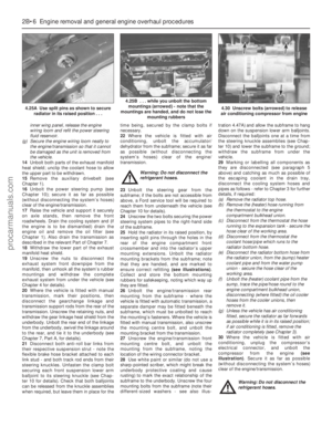 72
72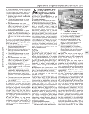 73
73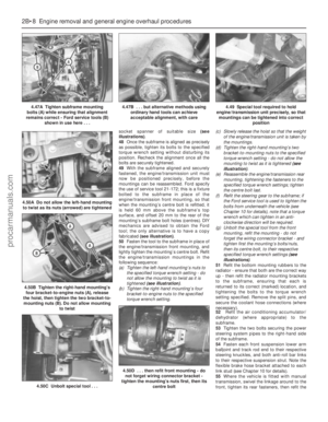 74
74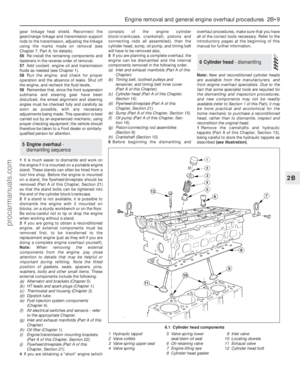 75
75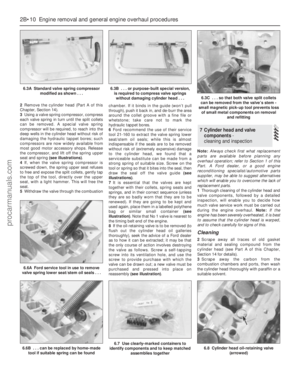 76
76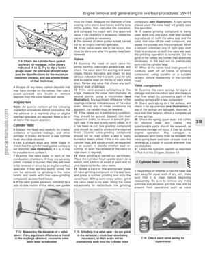 77
77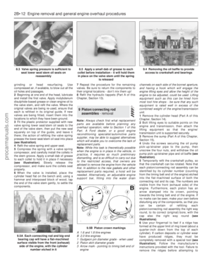 78
78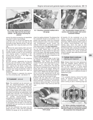 79
79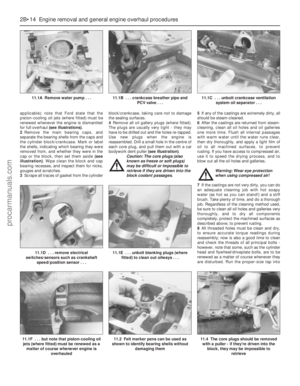 80
80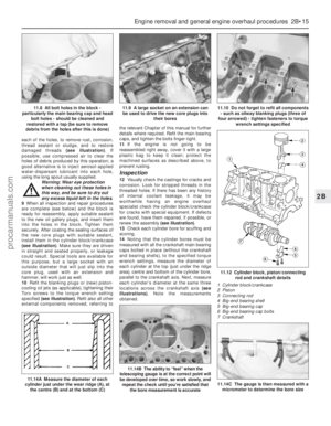 81
81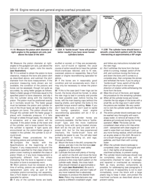 82
82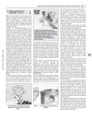 83
83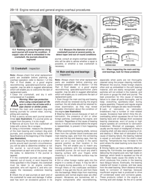 84
84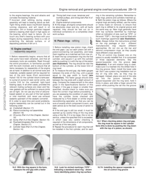 85
85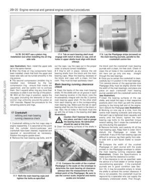 86
86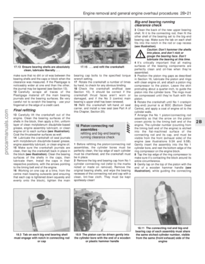 87
87 88
88 89
89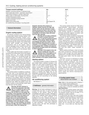 90
90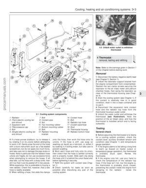 91
91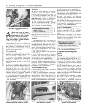 92
92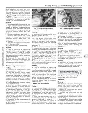 93
93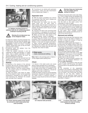 94
94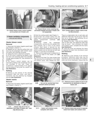 95
95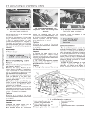 96
96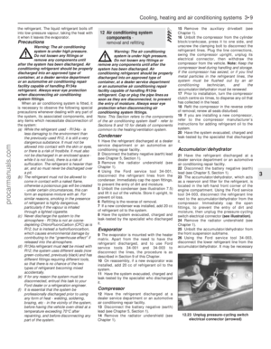 97
97 98
98 99
99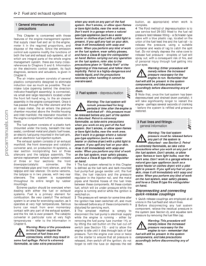 100
100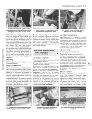 101
101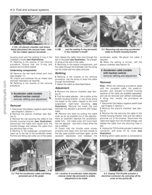 102
102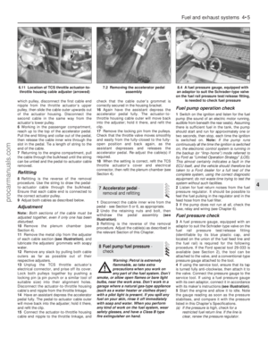 103
103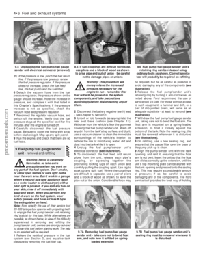 104
104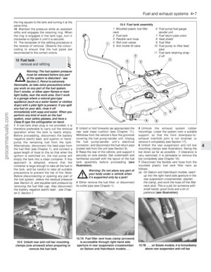 105
105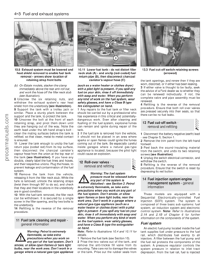 106
106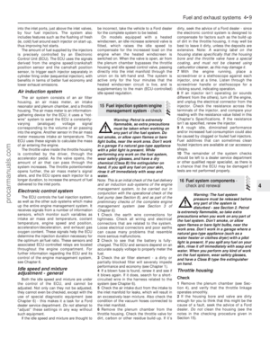 107
107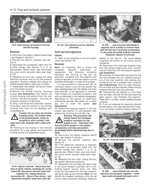 108
108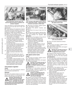 109
109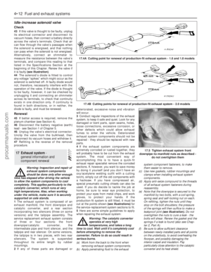 110
110 111
111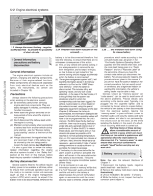 112
112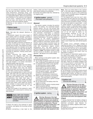 113
113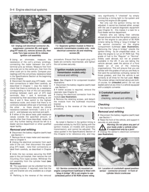 114
114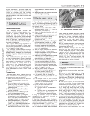 115
115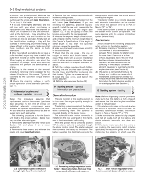 116
116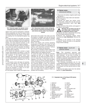 117
117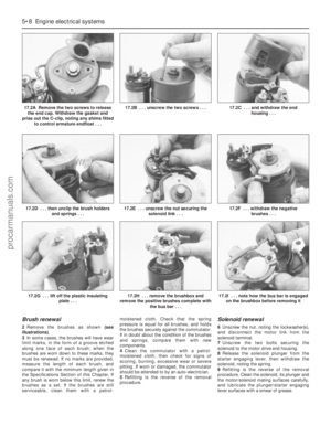 118
118 119
119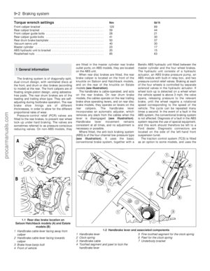 120
120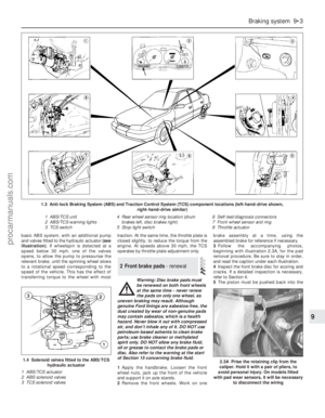 121
121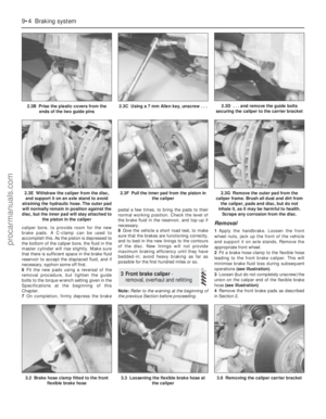 122
122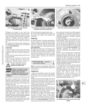 123
123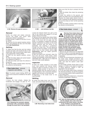 124
124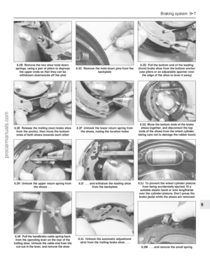 125
125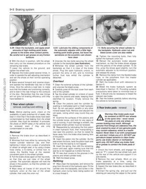 126
126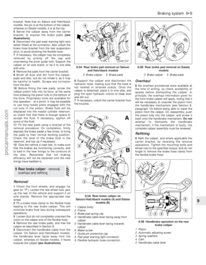 127
127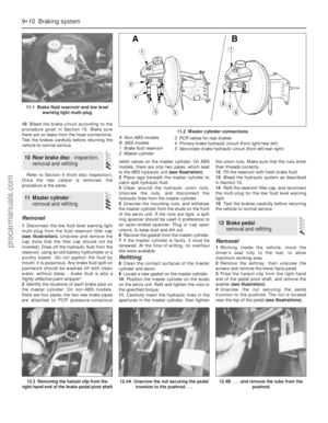 128
128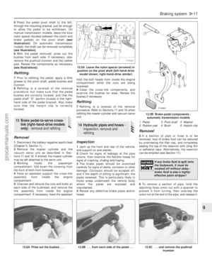 129
129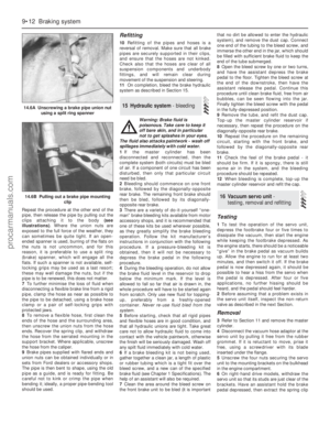 130
130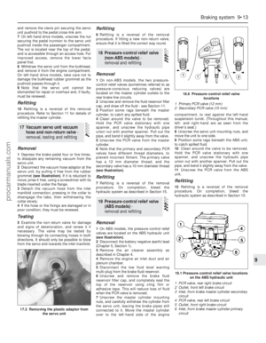 131
131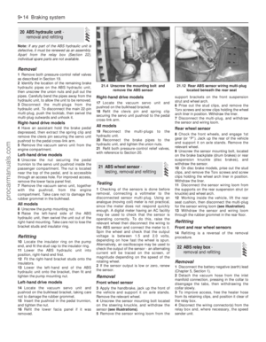 132
132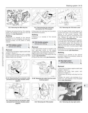 133
133 134
134 135
135 136
136 137
137 138
138 139
139 140
140 141
141 142
142 143
143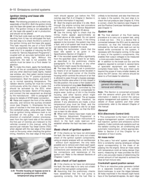 144
144 145
145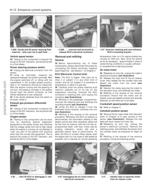 146
146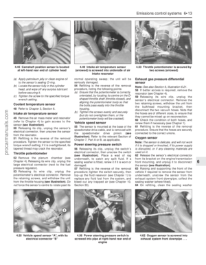 147
147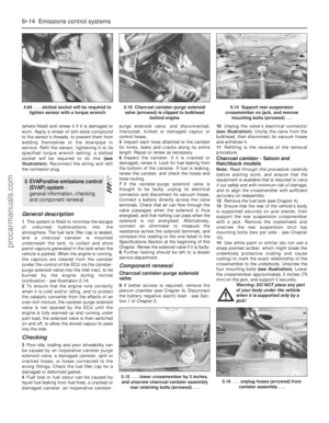 148
148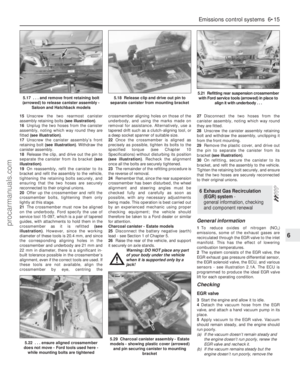 149
149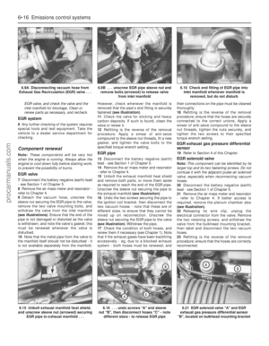 150
150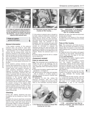 151
151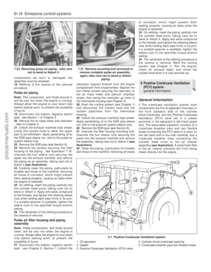 152
152 153
153 154
154 155
155 156
156 157
157 158
158 159
159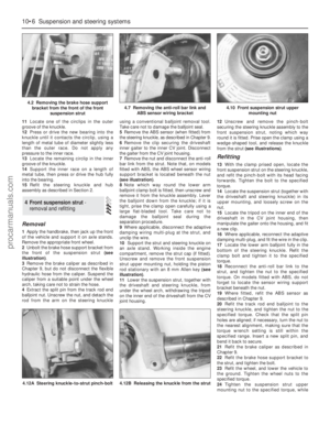 160
160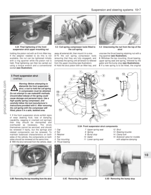 161
161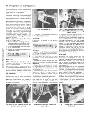 162
162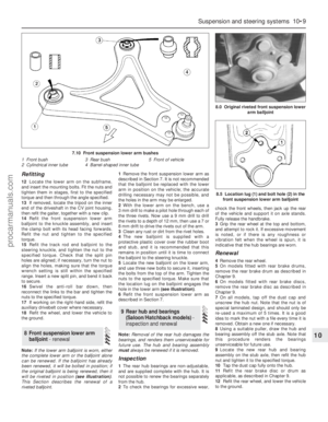 163
163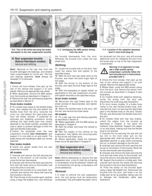 164
164 165
165 166
166 167
167 168
168 169
169 170
170 171
171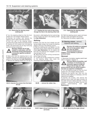 172
172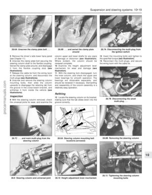 173
173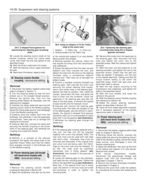 174
174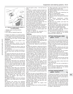 175
175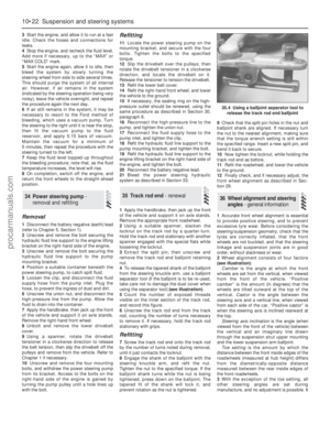 176
176 177
177 178
178 179
179 180
180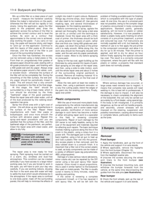 181
181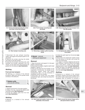 182
182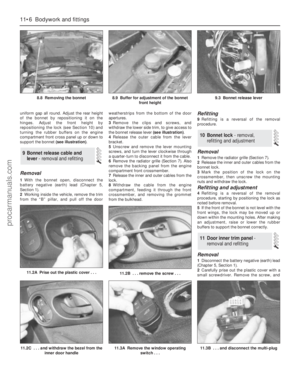 183
183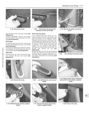 184
184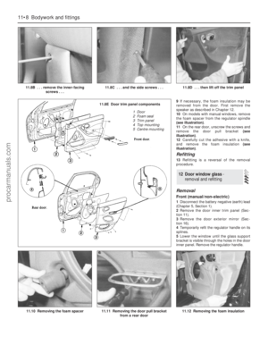 185
185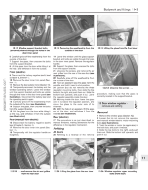 186
186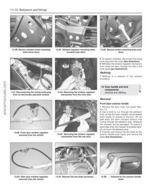 187
187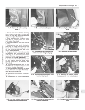 188
188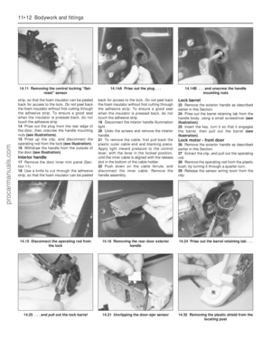 189
189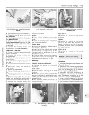 190
190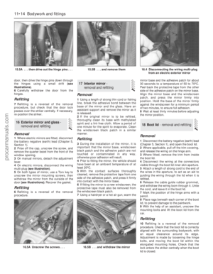 191
191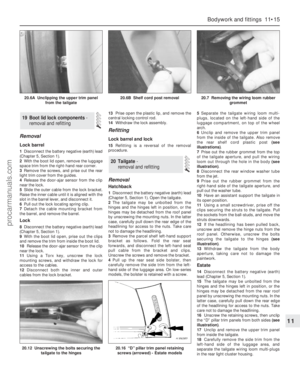 192
192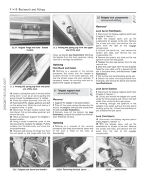 193
193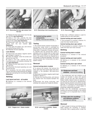 194
194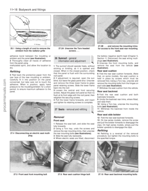 195
195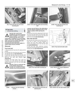 196
196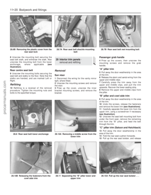 197
197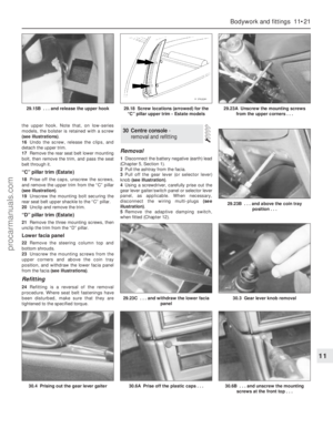 198
198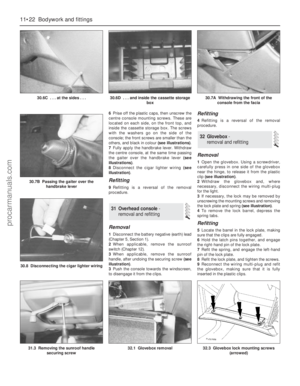 199
199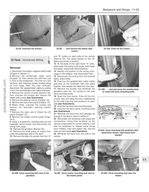 200
200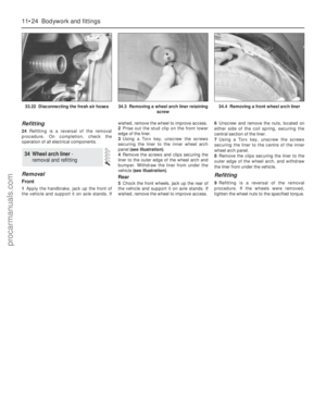 201
201 202
202 203
203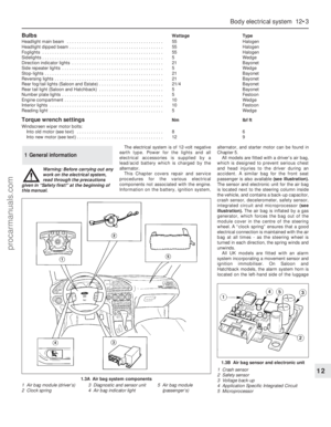 204
204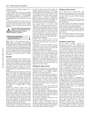 205
205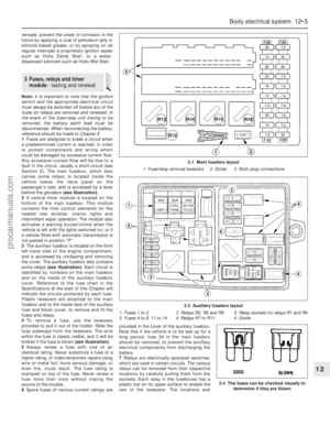 206
206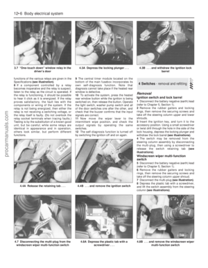 207
207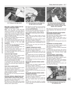 208
208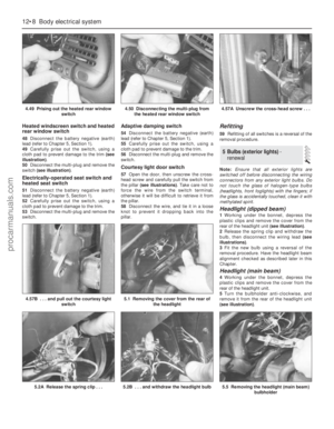 209
209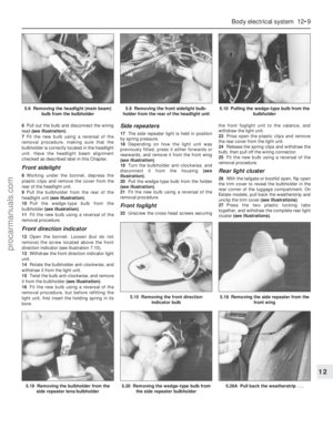 210
210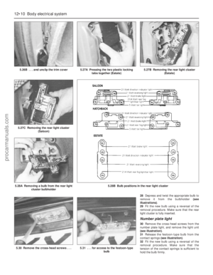 211
211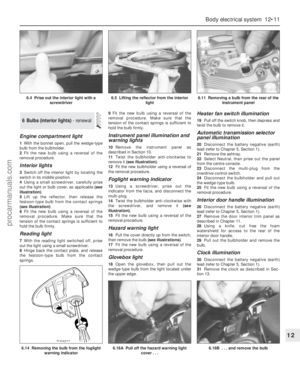 212
212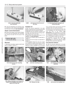 213
213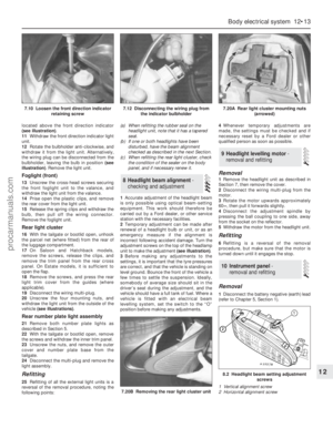 214
214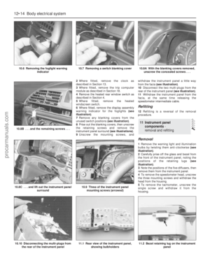 215
215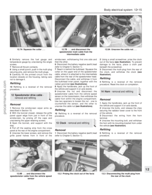 216
216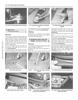 217
217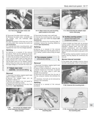 218
218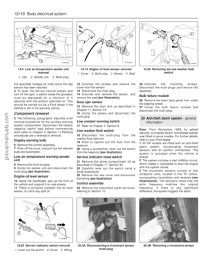 219
219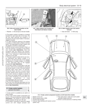 220
220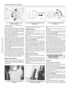 221
221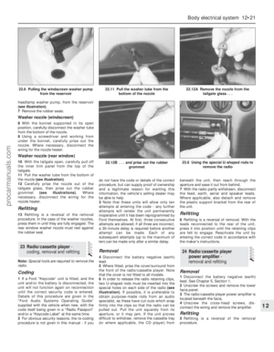 222
222 223
223 224
224 225
225 226
226 227
227 228
228 229
229 230
230 231
231 232
232 233
233 234
234 235
235 236
236 237
237 238
238 239
239 240
240 241
241 242
242 243
243 244
244 245
245 246
246 247
247 248
248 249
249 250
250 251
251 252
252 253
253 254
254 255
255 256
256 257
257 258
258 259
259 260
260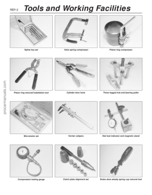 261
261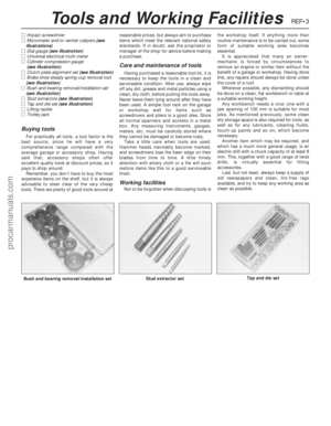 262
262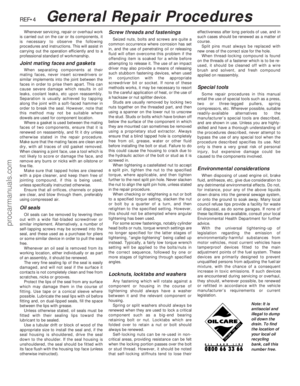 263
263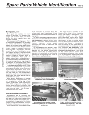 264
264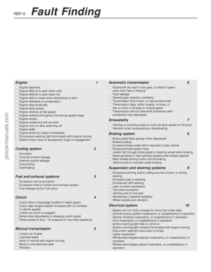 265
265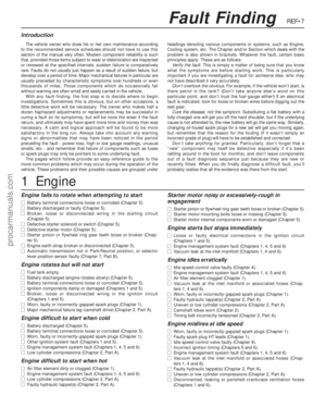 266
266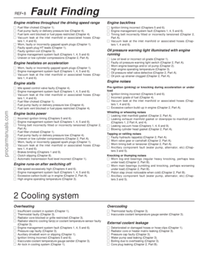 267
267 268
268 269
269 270
270 271
271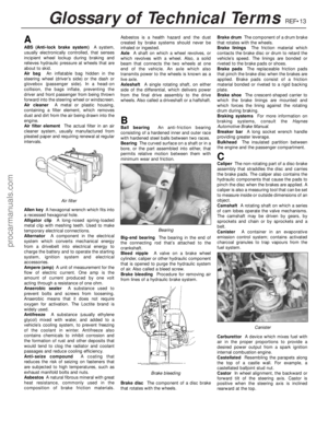 272
272 273
273 274
274 275
275 276
276 277
277 278
278