Page 97 of 279

the refrigerant. The liquid refrigerant boils off
into low-pressure vapour, taking the heat with
it when it leaves the evaporator.
Precautions
Warning: The air conditioning
system is under high pressure.
Do not loosen any fittings or
remove any components until
after the system has been discharged. Air
conditioning refrigerant should be properly
discharged into an approved type of
container, at a dealer service department
or an automotive air conditioning repair
facility capable of handling R134a
refrigerant. Always wear eye protection
when disconnecting air conditioning
system fittings.
When an air conditioning system is fitted, it
is necessary to observe the following special
precautions whenever dealing with any part of
the system, its associated components, and
any items which necessitate disconnection of
the system:
(a) While the refrigerant used - R134a - is
less damaging to the environment than
the previously-used R12, it is still a very
dangerous substance. It must not be
allowed into contact with the skin or eyes,
or there is a risk of frostbite. It must also
not be discharged in an enclosed space -
while it is not toxic, there is a risk of
suffocation. The refrigerant is heavier than
air, and so must never be discharged over
a pit.
(b) The refrigerant must not be allowed to
come in contact with a naked flame,
otherwise a poisonous gas will be created
- under certain circumstances, this can
form an explosive mixture with air. For
similar reasons, smoking in the presence
of refrigerant is highly dangerous,
particularly if the vapour is inhaled
through a lighted cigarette.
(c) Never discharge the system to the
atmosphere - R134a is not an ozone-
depleting ChloroFluoroCarbon (CFC) as is
R12, but is instead a hydrofluorocarbon,
which causes environmental damage by
contributing to the “greenhouse effect” if
released into the atmosphere.
(d) R134a refrigerant must notbe mixed with
R12; the system uses different seals (now
green-coloured, previously black) and has
different fittings requiring different tools,
so that there is no chance of the two
types of refrigerant becoming mixed
accidentally.
(e) If for any reason the system must be
disconnected, entrust this task to your
Ford dealer or a refrigeration engineer.
(f) It is essential that the system be
professionally discharged prior to using
any form of heat - welding, soldering,
brazing, etc - in the vicinity of the system,
before having the vehicle oven-dried at a
temperature exceeding 70°C after
repainting, and before disconnecting any
part of the system.Warning: The air conditioning
system is under high pressure.
Do not loosen any fittings or
remove any components until after the
system has been discharged. Air
conditioning refrigerant should be properly
discharged into an approved type of
container, at a dealer service department
or an automotive air conditioning repair
facility capable of handling R134a
refrigerant. Cap or plug the pipe lines as
soon as they are disconnected, to prevent
the entry of moisture. Always wear eye
protection when disconnecting air
conditioning system fittings.
Note: This Section refers to the components
of the air conditioning system itself - refer to
Sections 9 and 10 for details of components
common to the heating/ventilation system.
Condenser
1Have the refrigerant discharged at a dealer
service department or an automotive air
conditioning repair facility.
2Disconnect the battery negative (earth) lead
(see Chapter 5, Section 1).
3Remove the radiator undershield (see
Chapter 1).
4Using the Ford service tool 34-001,
disconnect the refrigerant lines from the
condenser. Immediately cap the open fittings,
to prevent the entry of dirt and moisture.
5Unbolt the condenser (see illustration 7.5)
and lift it out of the vehicle. Store it upright, to
prevent oil loss.
6Refitting is the reverse of removal.
7If a new condenser was installed, add 20 cc
of refrigerant oil to the system.
8Have the system evacuated, charged and
leak-tested by the specialist who discharged
it.
Evaporator
9The evaporator is mounted with the heater
matrix. Apart from the need to have the
refrigerant discharged, and to use Ford
service tools 34-001 and 34-003 to
disconnect the lines, the procedure is as
described in Section 9 of this Chapter.
10On reassembly, if a new evaporator was
installed, add 20 cc of refrigerant oil to the
system.
11Have the system evacuated, charged and
leak-tested by the specialist who discharged
it.
Compressor
12Have the refrigerant discharged at a
dealer service department or an automotive
air conditioning repair facility.
13Disconnect the battery negative (earth)
lead (see Chapter 5, Section 1).
14Remove the radiator undershield (see
Chapter 1).15Remove the auxiliary drivebelt (see
Chapter 1).
16Unbolt the compressor from the cylinder
block/crankcase, press it to one side, and
unscrew the clamping bolt to disconnect the
refrigerant lines. Plug the line connections,
swing the compressor upright, unplug its
electrical connector, then withdraw the
compressor from the vehicle. Note:Keep the
compressor level during handling and storage.
If the compressor has seized, or if you find
metal particles in the refrigerant lines, the
system must be flushed out by an air
conditioning technician, and the
accumulator/dehydrator must be renewed.
17Prior to installation, turn the compressor
clutch centre six times, to disperse any oil that
has collected in the head.
18Refit the compressor in the reverse order
of removal; renew all seals disturbed.
19If you are installing a new compressor,
refer to the compressor manufacturer’s
instructions for adding refrigerant oil to the
system.
20Have the system evacuated, charged and
leak-tested by the specialist that discharged
it.
Accumulator/dehydrator
21Have the refrigerant discharged at a
dealer service department or an automotive
air conditioning repair facility.
22Disconnect the battery negative (earth)
lead (see Chapter 5, Section 1).
23The accumulator/dehydrator, which acts
as a reservoir and filter for the refrigerant, is
located in the left-hand front corner of the
engine compartment. Using the Ford service
tool 34-003, disconnect the refrigerant line
next to the accumulator/dehydrator from the
compressor. Immediately cap the open
fittings, to prevent the entry of dirt and
moisture, then unplug the pressure-cycling
switch electrical connector (see illustration).
24Remove the radiator undershield (see
Chapter 1).
25Unbolt the accumulator/dehydrator from
the front suspension subframe.
26Using the Ford service tool 34-003,
disconnect the lower refrigerant line from the
accumulator/dehydrator. It may be necessary
12 Air conditioning system
components -
removal and refitting
Cooling, heating and air conditioning systems 3•9
3
12.23 Unplug pressure-cycling switch
electrical connector (arrowed)
procarmanuals.com
Page 98 of 279

to unscrew the pressure-cycling switch to
allow the use of the tool. Immediately cap the
open fittings, to prevent the entry of dirt and
moisture.
27Withdraw the accumulator/dehydrator.
28Refit the accumulator/dehydrator in the
reverse order of removal; renew all seals
disturbed.
29If you are installing a new accumulator/
dehydrator, refer to the manufacturer’s
instructions for adding refrigerant oil to the
system.
30Have the system evacuated, charged and
leak-tested by the specialist that discharged
it.Pressure-cycling and pressure-
regulating switches
31Have the refrigerant discharged at a
dealer service department or an automotive
air conditioning repair facility.
32Disconnect the battery negative (earth)
lead (see Chapter 5, Section 1).
33Unplug the switch electrical connector,
and unscrew it (see illustration).
34Refitting is the reverse of the removal
procedure; there is no need to top-up the
refrigerant oil.
35Have the system evacuated, charged and
leak-tested by the specialist that discharged
it.
3•10 Cooling, heating and air conditioning systems
12.33 Unplug pressure-regulating switch
electrical connector (arrowed)
procarmanuals.com
Page 99 of 279
 -
removal, refitting and adjustment . . . . . . . . . . . . . . . . . . . . . . . . . 6
Accelerator cable (models")
Chapter 4 Fuel and exhaust systems
Accelerator cable (models with traction control) -
removal, refitting and adjustment . . . . . . . . . . . . . . . . . . . . . . . . . 6
Accelerator cable (models without traction control) -
removal, refitting and adjustment . . . . . . . . . . . . . . . . . . . . . . . . . 5
Accelerator pedal - removal and refitting . . . . . . . . . . . . . . . . . . . . . 7
Air cleaner assembly/air intake components - removal and refitting . 4
Air filter element renewal . . . . . . . . . . . . . . . . . . . . . . . See Chapter 1
Catalytic converter . . . . . . . . . . . . . . . . . . . . . . . . . . . . See Chapter 6
Exhaust manifold - removal and refitting . . . . . . . . . . . See Chapter 2A
Exhaust system - general information and component renewal . . . . 17
Exhaust system check . . . . . . . . . . . . . . . . . . . . . . . . . See Chapter 1
Fuel cut-off switch - removal and refitting . . . . . . . . . . . . . . . . . . . . 13
Fuel filter renewal . . . . . . . . . . . . . . . . . . . . . . . . . . . . . See Chapter 1
Fuel injection system/engine management system - check . . . . . . . 15
Fuel injection system/engine management system - general . . . . . 14Fuel lines and fittings - general information . . . . . . . . . . . . . . . . . . . 3
Fuel pump/fuel gauge sender unit - removal and refitting . . . . . . . . 9
Fuel pump/fuel pressure - check . . . . . . . . . . . . . . . . . . . . . . . . . . . 8
Fuel system - depressurisation . . . . . . . . . . . . . . . . . . . . . . . . . . . . . 2
Fuel system components - check and renewal . . . . . . . . . . . . . . . . 16
Fuel tank - removal and refitting . . . . . . . . . . . . . . . . . . . . . . . . . . . . 10
Fuel tank cleaning and repair - general information . . . . . . . . . . . . . 11
General information and precautions . . . . . . . . . . . . . . . . . . . . . . . . 1
Idle speed and mixture check and adjustment . . . . . . See Section 14
Inlet manifold - removal and refitting . . . . . . . . . . . . . . See Chapter 2A
Oxygen sensor . . . . . . . . . . . . . . . . . . . . . . . . . . . . . . . See Chapter 6
Roll-over valves - removal and refitting . . . . . . . . . . . . . . . . . . . . . . . 12
Underbody fuel/brake line check . . . . . . . . . . . . . . . . . See Chapter 1
Underbonnet hose check . . . . . . . . . . . . . . . . . . . . . . . See Chapter 1
General
Idle speed:
Regulated - nominal (± 50 rpm) . . . . . . . . . . . . . . . . . . . . . . . . . . . . . . 830 to 880 rpm*
Unregulated - base . . . . . . . . . . . . . . . . . . . . . . . . . . . . . . . . . . . . . . . 1500 rpm*
Idle mixture (CO level) . . . . . . . . . . . . . . . . . . . . . . . . . . . . . . . . . . . . . . . Not available
* Given for reference only - not adjustable.
Rev limiter operation
Fuel injectors shut off at:
Automatic transmission, position “N” selected . . . . . . . . . . . . . . . . . . 4100 rpm
Automatic transmission, any other position selected . . . . . . . . . . . . . 6800 rpm (approximately)
Manual transmission . . . . . . . . . . . . . . . . . . . . . . . . . . . . . . . . . . . . . . 6800 to 7100 rpm
Fuel pressure
Regulated fuel pressure - engine running at idle speed:
Pressure regulator vacuum hose connected . . . . . . . . . . . . . . . . . . . 2.1 ± 0.2 bars
Pressure regulator vacuum hose disconnected . . . . . . . . . . . . . . . . . 2.7 ± 0.2 bars
Note:When the ignition is switched off, the system should hold 1.8 bars for 5 minutes. If the engine is hot, the pressure may rise to maximum of
2.7 bars during this check. Pressure regulator (when reconnected) should prevent any higher pressure being reached.
Fuel injectors
Resistance . . . . . . . . . . . . . . . . . . . . . . . . . . . . . . . . . . . . . . . . . . . . . . . . 13.7 to 15.2 ohms
Idle speed control valve
Resistance . . . . . . . . . . . . . . . . . . . . . . . . . . . . . . . . . . . . . . . . . . . . . . . . 6 to 14 ohms
Idle-increase solenoid valve
Resistance . . . . . . . . . . . . . . . . . . . . . . . . . . . . . . . . . . . . . . . . . . . . . . . . 50 to 120 ohms
Torque wrench settingsNm lbf ft
Plenum chamber-to-inlet manifold fasteners . . . . . . . . . . . . . . . . . . . . . 4 3
Throttle housing-to-inlet manifold screws . . . . . . . . . . . . . . . . . . . . . . . 10 7
Idle speed control valve bolts . . . . . . . . . . . . . . . . . . . . . . . . . . . . . . . . . 6 4
Fuel pressure regulator bolts . . . . . . . . . . . . . . . . . . . . . . . . . . . . . . . . . 6 4
Fuel injector bolts . . . . . . . . . . . . . . . . . . . . . . . . . . . . . . . . . . . . . . . . . . 6 4
Fuel rail-to-inlet manifold bolts . . . . . . . . . . . . . . . . . . . . . . . . . . . . . . . . 10 7
Fuel feed and return line threaded couplings at fuel rail . . . . . . . . . . . . . 24 to 30 17 to 22
All exhaust system nuts and bolts . . . . . . . . . . . . . . . . . . . . . . . . . . . . . 40 to 45 30 to 33
4•1
Easy,suitable for
novice with little
experienceFairly easy,suitable
for beginner with
some experienceFairly difficult,suitable
for competent DIY
mechanicDifficult,suitable for
experienced DIY
mechanicVery difficult,
suitable for expert DIY
or professional
Degrees of difficulty
Specifications Contents
4
procarmanuals.com
Page 100 of 279

This Chapter is concerned with those
features of the engine management system
that supply clean fuel and air to the engine,
meter it in the required proportions, and
dispose of the results. Since the emission
control sub-systems modify the functions of
both the fuel and exhaust sub-systems, all of
which are integral parts of the whole engine
management system, there are many cross-
references to Chapters 5 and 6. Information
on the electronic control system, its fault
diagnosis, sensors and actuators, is given in
Chapter 6.
The air intake system consists of several
plastics components designed to eliminate
induction roar as much as possible. The air
intake tube (opening behind the direction
indicator/headlight assembly) is connected,
via small and large resonators located under
the front left-hand wing, to the air cleaner
assembly in the engine compartment. Once it
has passed through the filter element and the
air mass meter, the air enters the plenum
chamber mounted above the throttle housing
and inlet manifold; the resonator mounted in
the engine compartment further reduces noise
levels.
The fuel system consists of a plastic tank
(mounted under the body, beneath the rear
seats), combined metal and plastic fuel hoses,
an electric fuel pump mounted in the fuel tank,
and an electronic fuel injection system.
The exhaust system consists of an exhaust
manifold, the front downpipe and catalytic
converter and, on production-fit systems, a
rear section incorporating two or three
silencers and the tailpipe assembly. The
service replacement exhaust system consists
of three or four sections: the front
downpipe/catalytic converter, the
intermediate pipe and front silencer, and the
tailpipe and rear silencer. On some versions,
the tailpipe is in two pieces, with two rear
silencers. The system is suspended
throughout its entire length by rubber
mountings.
Extreme caution should be exercised when
dealing with either the fuel or exhaust
systems. Fuel is a primary element for
combustion. Be very careful! The exhaust
system is an area for exercising caution, as it
operates at very high temperatures. Serious
burns can result from even momentary
contact with any part of the exhaust system,
and the fire risk is ever-present. The catalytic
converter in particular runs at very high
temperatures - refer to the information in
Chapter 6.
Warning: Many of the procedures
in this Chapter require the
removal of fuel lines and
connections, which may result in
some fuel spillage. Petrol is extremely
flammable, so take extra precautionswhen you work on any part of the fuel
system. Don’t smoke, or allow open flames
or bare light bulbs, near the work area.
Don’t work in a garage where a natural
gas-type appliance (such as a water
heater or clothes dryer) with a pilot light is
present. If you spill any fuel on your skin,
rinse it off immediately with soap and
water. When you perform any kind of work
on the fuel system, wear safety glasses,
and have a Class B type fire extinguisher
on hand. Before carrying out any operation
on the fuel system, refer also to the
precautions given in “Safety first!” at the
beginning of this manual, and follow them
implicitly. Petrol is a highly-dangerous and
volatile liquid, and the precautions
necessary when handling it cannot be
overstressed.
Warning: The fuel system will
remain pressurised for long
periods of time after the engine is
switched off - this pressure must
be released before any part of the system
is disturbed. Petrol is extremely
flammable, so take extra precautions
when you work on any part of the fuel
system. Don’t smoke, or allow open flames
or bare light bulbs, near the work area.
Don’t work in a garage where a natural
gas-type appliance (such as a water
heater or clothes dryer) with a pilot light is
present. If you spill any fuel on your skin,
rinse it off immediately with soap and
water. When you perform any kind of work
on the fuel system, wear safety glasses,
and have a Class B type fire extinguisher
on hand.
1The fuel system referred to in this Chapter
is defined as the fuel tank and tank-mounted
fuel pump/fuel gauge sender unit, the fuel
filter, the fuel injectors and the pressure
regulator in the injector rail, and the metal
pipes and flexible hoses of the fuel lines
between these components. All these contain
fuel, which will be under pressure while the
engine is running and/or while the ignition is
switched on.
2The pressure will remain for some time after
the ignition has been switched off, and must
be relieved before any of these components is
disturbed for servicing work.
3The simplest method is simply to
disconnect the fuel pump’s electrical supply
while the engine is running - either by
removing the fuel pump fuse (number 14), or
by lifting the red button on the fuel cut-off
switch (see Section 13) - and to allow the
engine to idle until it dies through lack of fuel
pressure. Turn the engine over once or twice
on the starter to ensure that all pressure is
released, then switch off the ignition; do not
forget to refit the fuse (or depress the redbutton, as appropriate) when work is
complete.
4The Ford method of depressurisation is to
use service tool 29-033 fitted to the fuel rail
pressure test/release fitting - a Schrader-type
valve with a blue plastic cap, located on the
union of the fuel feed line and the fuel rail - to
release the pressure, using a suitable
container and wads of rag to catch the spilt
fuel. Do notsimply depress the valve core to
release fuel pressure - droplets of fuel will
spray out, with a consequent risk of fire, and
of personal injury through fuel getting into
your eyes.
Warning: Either procedure will
merely relieve the increased
pressure necessary for the
engine to run. Remember that
fuel will still be present in the system
components, and take precautions
accordingly before disconnecting any of
them.
5Note that, once the fuel system has been
depressurised and drained (even partially), it
will take significantly longer to restart the
engine - perhaps several seconds of cranking
- before the system is refilled and pressure
restored.
Warning: The fuel system
pressure must be released before
any part of the system is
disturbed - see Section 2. Petrol
is extremely flammable, so take extra
precautions when you work on any part of
the fuel system. Don’t smoke, or allow
open flames or bare light bulbs, near the
work area. Don’t work in a garage where a
natural gas-type appliance (such as a
water heater or clothes dryer) with a pilot
light is present. If you spill any fuel on your
skin, rinse it off immediately with soap and
water. When you perform any kind of work
on the fuel system, wear safety glasses,
and have a Class B type fire extinguisher
on hand.
Disconnecting and connecting
quick-release couplings
1Quick-release couplings are employed at all
unions in the fuel feed and return lines.
2Before disconnecting any fuel system
component, relieve the residual pressure in
the system (see Section 2), and equalise tank
pressure by removing the fuel filler cap.
Warning: This procedure will
merely relieve the increased
pressure necessary for the
engine to run - remember that
fuel will still be present in the system
components, and take precautions
accordingly before disconnecting any of
them.
3 Fuel lines and fittings-
general information
2 Fuel system - depressurisation
1 General information and
precautions
4•2 Fuel and exhaust systems
procarmanuals.com
Page 101 of 279

3Release the protruding locking lugs on each
union, by squeezing them together and
carefully pulling the coupling apart. Use rag to
soak up any spilt fuel. Where the unions are
colour-coded, the pipes cannot be confused.
Where both unions are the same colour, note
carefully which pipe is connected to which,
and ensure that they are correctly
reconnected on refitting (see illustration).
4To reconnect one of these couplings, press
them together until the locking lugs snap into
their groove. Switch the ignition on and off
five times to pressurise the system, and check
for any sign of fuel leakage around the
disturbed coupling before attempting to start
the engine.
Checking
5Checking procedures for the fuel lines are
included in Chapter 1.
Component renewal
6If you must renew any damaged sections,
use original-equipment replacement hoses or
pipes, constructed from exactly the same
material as the section you are replacing. Do
not install substitutes constructed from
inferior or inappropriate material, or you could
cause a fuel leak or a fire.
7Before detaching or disconnecting any part
of the fuel system, note the routing of all
hoses and pipes, and the orientation of all
clamps and clips. Replacement sections must
be installed in exactly the same manner.8Before disconnecting any part of the fuel
system, be sure to relieve the fuel system
pressure (see Section 2), and equalise tank
pressure by removing the fuel filler cap. Also
disconnect the battery negative (earth) lead -
see Chapter 5, Section 1. Cover the fitting
being disconnected with a rag, to absorb any
fuel that may spray out.
Air cleaner assembly
1Disconnect the battery negative (earth) lead
- see Chapter 5, Section 1.
2Unclip the air mass meter from the air
cleaner cover (see Chapter 6).
3Disconnect the crankcase breather hose,
either from the air cleaner housing or from the
cylinder head cover union (see illustration).
4Remove the rubber retaining band (see
illustration). Withdraw the air cleaner
assembly, lifting it upwards out of its
grommets, and releasing it from the rubber
connector sleeve in the inner wing panel.
5Refitting is the reverse of the removal
procedure. Ensure that the housing pegs seat
correctly in their grommets, and that the
intake mouth is fully engaged inside the
connector sleeve (see illustration).
Air intake components
Note:Depending on the reason for removal,
these components can be removed either
individually, or as one assembly. For example,
unplugging the two electrical connectors and
disconnecting the vacuum hose (where fitted),
will allow the air cleaner assembly cover to be
removed with the air mass meter, the
resonator and the plenum chamber.
Air mass meter
6Refer to Section 4 of Chapter 6.
Resonator (engine compartment)
7Unbolt the resonator support bracket from
the engine compartment front crossmember.
Slacken the two clamp screws securing the
resonator to the air mass meter and plenum
chamber hoses. Swing the resonator clear of
the thermostat housing, and unplug the intake
air temperature sensor’s electrical connector
(see illustration). Withdraw the resonator.
8Refitting is the reverse of the removal
procedure.
Plenum chamber
9Prising out the rubber plugs covering them,
undo the chamber’s fasteners (see
illustration). Slacken the clamp screw
securing the chamber to the resonator hose.
10Lift the chamber and (where fitted)
disconnect the vacuum hose from its
underside. Withdraw the chamber - note the
two rubber spacers (one on each throttle
4 Air cleaner assembly and air
intake components -
removal and refitting
Fuel and exhaust systems 4•3
4
4.5 Ensure air filter housing intake mouth
is fully engaged inside connector sleeve4.7 Unplugging intake air temperature
sensor’s electrical connector4.9 Plenum chamber fasteners (arrowed) -
four shown here, some vehicles may only
have three
3.3 Disconnect fuel line quick-release
couplings by squeezing together protruding
locking lugs and pulling coupling apart4.3 Disconnecting the crankcase breather
hose from the cylinder head union4.4 Remove rubber retaining band to
withdraw air cleaner assembly
procarmanuals.com
Page 102 of 279
 and the sealing O-ring in the
chamber’s mouth (see illustrations).
11Refitting is the reverse of the removal
procedure. Ensure that the O-ring and
spacers are correctly seated.
Underwi")
housing stud) and the sealing O-ring in the
chamber’s mouth (see illustrations).
11Refitting is the reverse of the removal
procedure. Ensure that the O-ring and
spacers are correctly seated.
Underwing components
12Remove the left-hand wheel arch liner
(see Chapter 11).
13Unbolt and withdraw the air intake tube
and both resonators as required.
14Refitting is the reverse of the removal
procedure.
Removal
1Disconnect the battery negative (earth) lead
- see Chapter 5, Section 1.
2Remove the plenum chamber (see Sec-
tion 4).
3Remove the clip securing the cable to the
throttle housing bracket (see illustration).
Disconnect the cable end nipple from the
throttle linkage, and release the cable from
any securing clips or ties.
4Working in the passenger compartment,
reach up to the top of the accelerator pedal.
Pull the end fitting and collar out of the pedal,then release the cable inner wire through the
slot in the pedal (see illustration). Tie a length
of string to the end of the cable.
5Returning to the engine compartment, pull
the cable through the bulkhead until the string
can be untied and the cable removed.
Refitting
6Refitting is the reverse of the removal
procedure; use the string to draw the cable
through the bulkhead.
7Adjust the cable as described below.
Adjustment
8Remove the plenum chamber (see Sec-
tion 4).
9Find the cable adjuster - this is either at the
throttle housing bracket, or two-thirds along
the length of the cable, clipped to the front
suspension right-hand mounting (see
illustration). Remove the metal clip and
lubricate the adjuster’s grommet with soapy
water.
10Remove any slack by pulling the cable
outer as far as possible out of the adjuster.
Have an assistant depress the accelerator
pedal fully - the cable outer will move back
into the adjuster - and hold it there while the
clip is refitted.
11Check that the throttle valve moves
smoothly and easily from the fully-closed to
the fully-open position and back again, as the
assistant depresses and releases theaccelerator pedal. Re-adjust the cable if
required.
12When the setting is correct, refit the
plenum chamber (see Section 4).
Removal
Note:While the following procedure deals
with the complete cable, the pedal-to-
actuator and actuator-to-throttle housing
sections of the cable are available separately,
and can be removed and refitted individually.
If doing this, modify the procedure as
required.
1Disconnect the battery negative (earth) lead
- see Chapter 5, Section 1.
2Remove the plenum chamber (see Sec-
tion 4).
3Remove the clip securing the cable to the
throttle housing bracket, then pull the cable’s
grommet out of the bracket. Disconnect the
cable end nipple from the throttle linkage, and
release the cable from any securing clips or
ties.
4Unplug the TCS throttle actuator’s electrical
connector, and prise off its cover (see
illustration).
5Noting which cable section is connected to
6 Accelerator cable (models
with traction control)-
removal, refitting and adjustment
5 Accelerator cable (models
without traction control) -
removal, refitting and adjustment
4•4 Fuel and exhaust systems
4.10A Lift plenum chamber and (where
fitted) disconnect the vacuum hose - note
the two rubber spacers (arrowed) . . .4.10B . . . and the sealing O-ring (arrowed)
in the chamber’s mouth5.3 Removing clip securing accelerator
cable to throttle housing bracket
5.4 Pull the accelerator cable end fitting
(arrowed) out of the pedal5.9 Location of accelerator cable adjuster
- remove metal clip (arrowed) to enable
adjustment to be made6.4 Unplug TCS throttle actuator’s
electrical connector (A), and prise off its
cover at two points (B)
procarmanuals.com
Page 103 of 279

which pulley, disconnect the first cable end
nipple from the throttle actuator’s upper
pulley, then slide the cable outer upwards out
of the actuator housing. Disconnect the
second cable in the same way from the
actuator’s lower pulley.
6Working in the passenger compartment,
reach up to the top of the accelerator pedal.
Pull the end fitting and collar out of the pedal,
then release the cable inner wire through the
slot in the pedal. Tie a length of string to the
end of the cable.
7Returning to the engine compartment, pull
the cable through the bulkhead until the string
can be untied and the pedal-to-actuator cable
removed.
Refitting
8Refitting is the reverse of the removal
procedure. Use the string to draw the pedal-
to-actuator cable through the bulkhead.
Ensure that each cable end is connected to
the correct actuator pulley.
9Adjust both cables as described below.
Adjustment
Note:Both sections of the cable must be
adjusted together, even if only one has been
disturbed.
10Remove the plenum chamber (see
Section 4).
11Remove the metal clip from the adjuster
of each cable section (see illustration), and
lubricate the adjusters’ grommets with soapy
water.
12Remove any slack by pulling both cable
outers as far as possible out of their
respective adjusters.
13Unplug the TCS throttle actuator’s
electrical connector, and prise off its cover.
Lock both pulleys together by pushing a
locking pin (a pin punch or a similar tool of
suitable size) into their alignment holes.
Disconnect the actuator-to-throttle housing
cable’s end nipple from the throttle linkage.
14Have an assistant depress the accelerator
pedal fully. The pedal-to-actuator cable outer
will move back into the adjuster; hold it there,
and refit the clip.
15Connect the actuator-to-throttle housing
cable end nipple to the throttle linkage, andcheck that the cable outer’s grommet is
correctly secured in the housing bracket.
16Again have the assistant depress the
accelerator pedal fully. The actuator-to-
throttle housing cable outer will move back
into the adjuster; hold it there, and refit the
clip.
17Remove the locking pin from the pulleys.
Check that the throttle valve moves smoothly
and easily from the fully-closed to the fully-
open position and back again, as the
assistant depresses and releases the
accelerator pedal. Re-adjust the cable(s) if
required.
18When the setting is correct, refit the TCS
throttle actuator’s cover and electrical
connector, then refit the plenum chamber (see
Section 4).
1Disconnect the cable inner wire from the
pedal - see Section 5 or 6, as appropriate.
2Undo the retaining nuts and bolt, then
withdraw the pedal assembly (see
illustration).
3Refitting is the reverse of the removal
procedure. Adjust the cable(s) as described in
the relevant Section of this Chapter.
Warning: Petrol is extremely
flammable, so take extra
precautions when you work on
any part of the fuel system. Don’t
smoke, or allow open flames or bare light
bulbs, near the work area. Don’t work in a
garage where a natural gas-type appliance
(such as a water heater or clothes dryer)
with a pilot light is present. If you spill any
fuel on your skin, rinse it off immediately
with soap and water. When you perform
any kind of work on the fuel system, wear
safety glasses, and have a Class B type
fire extinguisher on hand.
Fuel pump operation check
1Switch on the ignition and listen for the fuel
pump (the sound of an electric motor running,
audible from beneath the rear seats). Assuming
there is sufficient fuel in the tank, the pump
should start and run for approximately one or
two seconds, then stop, each time the ignition
is switched on. Note:If the pump runs
continuously all the time the ignition is switched
on, the electronic control system is running in
the backup (or “limp-home”) mode referred to
by Ford as “Limited Operation Strategy” (LOS).
This almost certainly indicates a fault in the
ECU itself, and the vehicle should therefore be
taken to a Ford dealer for a full test of the
complete system, using the correct diagnostic
equipment; do not waste time trying to test the
system without such facilities.
2Listen for fuel return noises from the fuel
pressure regulator. It should be possible to
feel the fuel pulsing in the regulator and in the
feed hose from the fuel filter.
3If the pump does not run at all, check the
fuse, relay and wiring (see Chapter 6).
Fuel pressure check
3A fuel pressure gauge, equipped with an
adaptor to suit the Schrader-type valve on the
fuel rail pressure test/release fitting
(identifiable by its blue plastic cap, and
located on the union of the fuel feed line and
the fuel rail) is required for the following
procedure. If the Ford special tool 29-033 is
available (see Section 2), the tool can be
attached to the valve, and a conventional-type
pressure gauge attached to the tool.
4If using the service tool, ensure that its tap
is turned fully anti-clockwise, then attach it to
the valve. Connect the pressure gauge to the
service tool. If using a fuel pressure gauge
with its own adaptor, connect it in accordance
with its maker’s instructions (see illustration).
5Start the engine and allow it to idle. Note
the gauge reading as soon as the pressure
stabilises, and compare it with the pressure
listed in this Chapter’s Specifications.
(a) If the pressure is high, check for a
restricted fuel return line. If the line is
clear, renew the pressure regulator.
8 Fuel pump/fuel pressure -
check
7 Accelerator pedal -
removal and refitting
Fuel and exhaust systems 4•5
4
6.11 Location of TCS throttle actuator-to-
throttle housing cable adjuster (arrowed)7.2 Removing the accelerator pedal
assembly8.4 A fuel pressure gauge, equipped with
an adaptor to suit the Schrader-type valve
on the fuel rail pressure test/release fitting,
is needed to check fuel pressure
procarmanuals.com
Page 104 of 279
 If the pressure is low, pinch the fuel return
line. If the pressure now goes up, renew
the fuel pressure regulator. If the pressure
does not increase, check the fuel feed
line, the fuel pump and t")
(b) If the pressure is low, pinch the fuel return
line. If the pressure now goes up, renew
the fuel pressure regulator. If the pressure
does not increase, check the fuel feed
line, the fuel pump and the fuel filter.
6Detach the vacuum hose from the fuel
pressure regulator; the pressure shown on the
gauge should increase. Note the increase in
pressure, and compare it with that listed in
this Chapter’s Specifications. If the pressure
increase is not as specified, check the
vacuum hose and pressure regulator.
7Reconnect the regulator vacuum hose, and
switch off the engine. Verify that the fuel
pressure stays at the specified level for five
minutes after the engine is turned off.
8Carefully disconnect the fuel pressure
gauge. Be sure to cover the fitting with a rag
before slackening it. Mop up any spilt petrol.
9Run the engine, and check that there are no
fuel leaks.
Warning: Petrol is extremely
flammable, so take extra
precautions when you work on
any part of the fuel system. Don’t smoke,
or allow open flames or bare light bulbs,
near the work area. Don’t work in a garage
where a natural gas-type appliance (such
as a water heater or clothes dryer) with a
pilot light is present. If you spill any fuel on
your skin, rinse it off immediately with
soap and water. When you perform any
kind of work on the fuel system, wear
safety glasses, and have a Class B type
fire extinguisher on hand.
Note: Ford specify the use of their service tool
23-038 (a large box spanner with projecting teeth
to engage the fuel pump/sender unit retaining
ring’s slots) for this task. While alternatives are
possible, as shown below, in view of the difficulty
experienced in removing and refitting the
pump/sender unit, owners are strongly advised
to obtain this tool before starting work. The help
of an assistant will be required.
1Relieve the residual pressure in the fuel
system (see Section 2), and equalise tank
pressure by removing the fuel filler cap. Warning: This procedure will
merely relieve the increased
pressure necessary for the
engine to run - remember that
fuel will still be present in the system
components, and take precautions
accordingly before disconnecting any of
them.
2Disconnect the battery negative (earth) lead
- see Chapter 5, Section 1.
3Unbolt or fold forwards (as appropriate) the
rear seat base cushion (see Chapter 11).
Withdraw from the vehicle’s floor the grommet
covering the fuel pump/sender unit. Wash off
any dirt from the tank’s top surface, and dry it;
use a vacuum cleaner to clean the immediate
surroundings of the vehicle’s interior, to
reduce the risk of introducing water, dirt and
dust into the tank while it is open.
4Unplug the fuel pump/sender unit’s
electrical connector (see illustration).
5To disconnect the fuel feed and return
pipes from the unit, release each pipe’s
coupling, by squeezing together the
protruding locking lugs on each union and
carefully pulling the coupling apart. Use rag to
soak up any spilt fuel. Where the couplings
are difficult to separate, use a pair of pliers
and a block of wood as shown, to lever the
pipe out of the union. Considerable force maybe required, but be as careful as possible to
avoid damaging any of the components (see
illustration).
6Release the fuel pump/sender unit’s
retaining ring by turning it anti-clockwise. As
noted above, Ford recommend the use of
service tool 23-038. For those without access
to such equipment, a hammer and drift, or a
pair of slip-jointed pliers, will serve as an
adequate substitute - at least for removal (see
illustration).
7Withdraw the fuel pump/fuel gauge sender
unit, taking care not to bend the float arm. The
float arm is mounted on a spring-loaded
extension, to hold it closely against the
bottom of the tank. Note the sealing ring; this
must be renewed whenever it is disturbed
(see illustrations).
8On refitting, use a new sealing ring, and
ensure that the gauze filter over the base of
the pump pick-up is clean.
9Align the pump/sender unit with the tank
opening, and refit it, ensuring that the float
arm is not bent. Insert the unit so that the float
arm slides correctly up the extension, until the
unit’s top mounting plate can be aligned with
the tank opening and pressed onto the sealing
ring. This may require a considerable amount
of pressure; if so, be careful to avoid
damaging any of the components. The Ford
service tool provides the best way of holding
9 Fuel pump/fuel gauge sender
unit- removal and refitting
4•6 Fuel and exhaust systems
9.4 Unplugging the fuel pump/fuel gauge
sender unit electrical connector (arrowed)9.5 If fuel couplings are difficult to release,
use pliers and a block of wood as shown
to prise pipe end out of union - be careful
not to damage pipes or unions9.6 Fuel pump/fuel gauge sender unit’s
retaining ring can be released using
ordinary tools as shown. Correct service
tool will probably be required on refitting
9.7A Removing fuel pump/fuel gauge
sender unit - take care not to bend float
arm, and note how it is fitted on spring-
loaded extension9.7B Fuel pump/fuel gauge sender unit’s
sealing ring must be renewed whenever it
is disturbed
procarmanuals.com
 1
1 2
2 3
3 4
4 5
5 6
6 7
7 8
8 9
9 10
10 11
11 12
12 13
13 14
14 15
15 16
16 17
17 18
18 19
19 20
20 21
21 22
22 23
23 24
24 25
25 26
26 27
27 28
28 29
29 30
30 31
31 32
32 33
33 34
34 35
35 36
36 37
37 38
38 39
39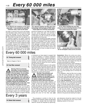 40
40 41
41 42
42 43
43 44
44 45
45 46
46 47
47 48
48 49
49 50
50 51
51 52
52 53
53 54
54 55
55 56
56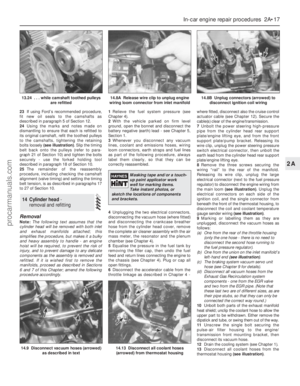 57
57 58
58 59
59 60
60 61
61 62
62 63
63 64
64 65
65 66
66 67
67 68
68 69
69 70
70 71
71 72
72 73
73 74
74 75
75 76
76 77
77 78
78 79
79 80
80 81
81 82
82 83
83 84
84 85
85 86
86 87
87 88
88 89
89 90
90 91
91 92
92 93
93 94
94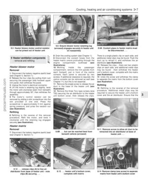 95
95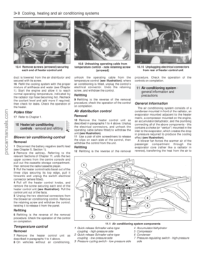 96
96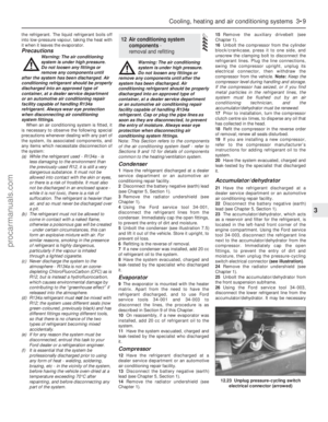 97
97 98
98 99
99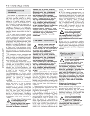 100
100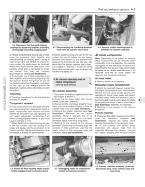 101
101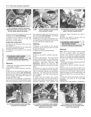 102
102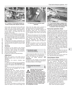 103
103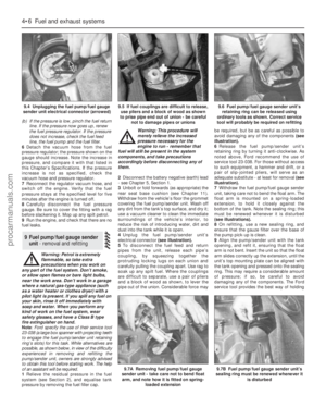 104
104 105
105 106
106 107
107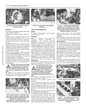 108
108 109
109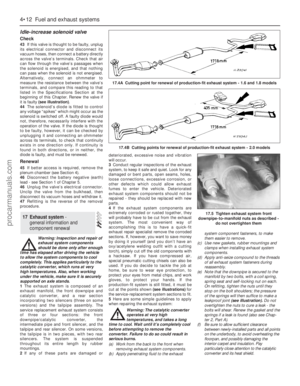 110
110 111
111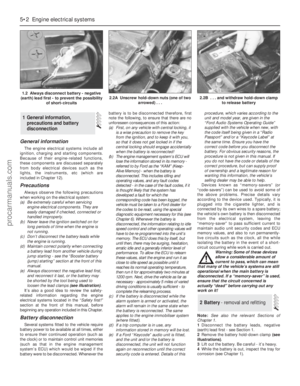 112
112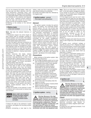 113
113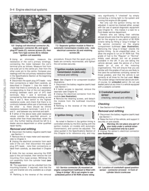 114
114 115
115 116
116 117
117 118
118 119
119 120
120 121
121 122
122 123
123 124
124 125
125 126
126 127
127 128
128 129
129 130
130 131
131 132
132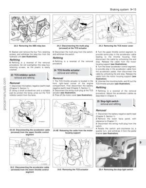 133
133 134
134 135
135 136
136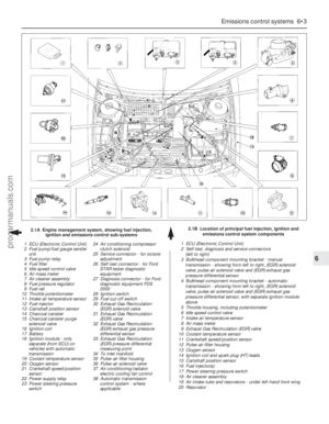 137
137 138
138 139
139 140
140 141
141 142
142 143
143 144
144 145
145 146
146 147
147 148
148 149
149 150
150 151
151 152
152 153
153 154
154 155
155 156
156 157
157 158
158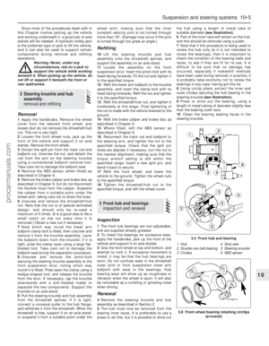 159
159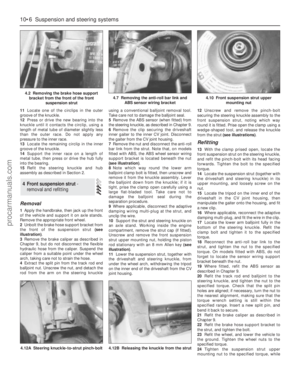 160
160 161
161 162
162 163
163 164
164 165
165 166
166 167
167 168
168 169
169 170
170 171
171 172
172 173
173 174
174 175
175 176
176 177
177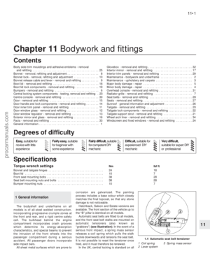 178
178 179
179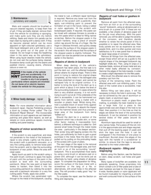 180
180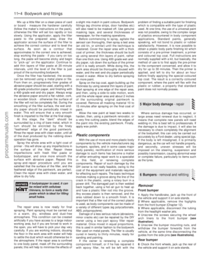 181
181 182
182 183
183 184
184 185
185 186
186 187
187 188
188 189
189 190
190 191
191 192
192 193
193 194
194 195
195 196
196 197
197 198
198 199
199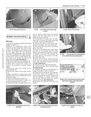 200
200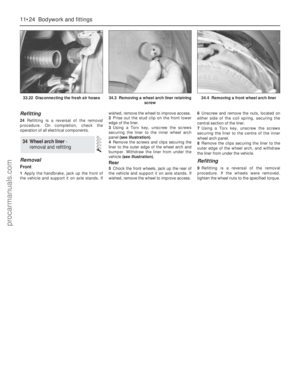 201
201 202
202 203
203 204
204 205
205 206
206 207
207 208
208 209
209 210
210 211
211 212
212 213
213 214
214 215
215 216
216 217
217 218
218 219
219 220
220 221
221 222
222 223
223 224
224 225
225 226
226 227
227 228
228 229
229 230
230 231
231 232
232 233
233 234
234 235
235 236
236 237
237 238
238 239
239 240
240 241
241 242
242 243
243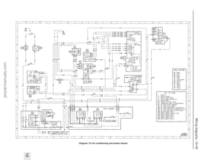 244
244 245
245 246
246 247
247 248
248 249
249 250
250 251
251 252
252 253
253 254
254 255
255 256
256 257
257 258
258 259
259 260
260 261
261 262
262 263
263 264
264 265
265 266
266 267
267 268
268 269
269 270
270 271
271 272
272 273
273 274
274 275
275 276
276 277
277 278
278