Page 153 of 279

2The function of these components is to
reduce the emission of unburned
hydrocarbons from the crankcase, and to
minimise the formation of oil sludge. By
ensuring that a depression is created in the
crankcase under most operating conditions,
particularly at idle, and by positively inducing
fresh air into the system, the oil vapours and
“blow-by” gases collected in the crankcase
are drawn from the crankcase, through the oil
separator, into the inlet tract, to be burned by
the engine during normal combustion.
Checking
3Checking procedures for the system
components are included in Chapter 1.
Component renewal
Cylinder head-to-air cleaner hose
4See Chapter 1.
Positive Crankcase Ventilation (PCV)
valve
5The valve is plugged into the oil separator.
Depending on the tools available, access to
the valve may be possible once the pulse-air
assembly has been removed (see Section 7).
If this is not feasible, proceed as outlined in
paragraph 6 below.
Oil separator
6Remove the exhaust manifold (see Chap-
ter 2, Part A). The Positive Crankcase
Ventilation (PCV) valve can now be unplugged
and flushed, or renewed, as required, as
described in Chapter 1.
7Unbolt the oil separator from the cylinder
block/crankcase, and withdraw it; remove and
discard the gasket.
8Flush out or renew the oil separator, as
required (see Chapter 1).
9On reassembly, fit a new gasket, and
tighten the fasteners to the torque wrench
settings given in the Specifications Section of
Chapter 2, Part B.
10The remainder of the refitting procedure is
the reverse of removal. Refill the cooling
system (see Chapter 1). Run the engine,
check for exhaust leaks, and check the
coolant level when it is fully warmed-up.
General information
1The exhaust gases of any petrol engine
(however efficient or well-tuned) consist
largely (approximately 99 %) of nitrogen (N
2),
carbon dioxide (CO
2), oxygen (O2), other inert
gases and water vapour (H
2O). The remaining
1 % is made up of the noxious materials
which are currently seen (CO
2apart) as the
major polluters of the environment: carbon
monoxide (CO), unburned hydrocarbons (HC),oxides of nitrogen (NO
x) and some solid
matter, including a small lead content.
2Left to themselves, most of these pollutants
are thought eventually to break down naturally
(CO and NO
x, for example, break down in the
upper atmosphere to release CO
2) having first
caused ground-level environmental problems.
The massive increase world-wide in the use of
motor vehicles, and the current popular
concern for the environment has caused the
introduction in most countries of legislation, in
varying degrees of severity, to combat the
problem.
3The device most commonly used to clean
up vehicle exhausts is the catalytic converter.
It is fitted into the vehicle’s exhaust system,
and uses precious metals (platinum and
palladium or rhodium) as catalysts to speed
up the reaction between the pollutants and
the oxygen in the vehicle’s exhaust gases, CO
and HC being oxidised to form H
2O and CO2and (in the three-way type of catalytic
converter) NO
xbeing reduced to N2. Note:
The catalytic converter is not a filter in the
physical sense; its function is to promote a
chemical reaction, but it is not itself affected
by that reaction.
4The converter consists of an element (or
“substrate”) of ceramic honeycomb, coated
with a combination of precious metals in such
a way as to produce a vast surface area over
which the exhaust gases must flow; the whole
being mounted in a stainless-steel box. A
simple “oxidation” (or “two-way”) catalytic
converter can deal with CO and HC only,
while a “reduction” (or “three-way”) catalytic
converter can deal with CO, HC and NO
x.
Three-way catalytic converters are further
sub-divided into “open-loop” (or
“uncontrolled”) converters which can remove
50 to 70 % of pollutants and “closed-loop”
(also known as “controlled” or “regulated”)
converters which can remove over 90 % of
pollutants.
5The catalytic converter fitted to the Mondeo
models covered in this manual is of the three-
way closed-loop type.
6The catalytic converter is a reliable and
simple device, which needs no maintenance
in itself, but there are some facts of which an
owner should be aware if the converter is to
function properly for its full service life.
(a) DO NOT use leaded petrol in a vehicle
equipped with a catalytic converter - the
lead will coat the precious metals,
reducing their converting efficiency, and
will eventually destroy the converter; it will
also affect the operation of the oxygen
sensor, requiring its renewal if lead-
fouled. Opinions vary as to how much
leaded fuel is necessary to affect the
converter’s performance, and whether it
can recover even if only unleaded petrol is
used afterwards; the best course of action
is, therefore, to assume the worst, and to
ensure that NO leaded petrol is used at
any time.
(b) Always keep the ignition and fuel systemswell-maintained in accordance with the
manufacturer’s schedule (Chapter 1) -
particularly, ensure that the air filter
element, the fuel filter and the spark plugs
are renewed at the correct intervals. If the
intake air/fuel mixture is allowed to
become too rich due to neglect, the
unburned surplus will enter and burn in
the catalytic converter, overheating the
element and eventually destroying the
converter.
(c) If the engine develops a misfire, do not
drive the vehicle at all (or at least as little
as possible) until the fault is cured - the
misfire will allow unburned fuel to enter
the converter, which will result in its
overheating, as noted above. For the
same reason, do not persist if the engine
refuses to start - either trace the problem
and cure it yourself, or have the vehicle
checked immediately by a qualified
mechanic.
(d) Avoid allowing the vehicle to run out of
petrol.
(e) DO NOT push- or tow-start the vehicle
unless no other alternative exists,
especially if the engine and exhaust are at
normal operating temperature. Starting
the engine in this way may soak the
catalytic converter in unburned fuel,
causing it to overheat when the engine
does start - see (b) above.
(f) DO NOT switch off the ignition at high
engine speeds, in particular, do not “blip”
the throttle immediately before switching
off. If the ignition is switched off at
anything above idle speed, unburned fuel
will enter the (very hot) catalytic converter,
with the possible risk of its igniting on the
element and damaging the converter.
(g) Avoid repeated successive cold starts
followed by short journeys. If the
converter is never allowed to reach its
proper working temperature, it will gather
unburned fuel, allowing some to pass into
the atmosphere and the rest to soak in
the element, causing it to overheat when
a long journey is made - see (b) above.
(h) DO NOT use fuel or engine oil additives -
these may contain substances harmful to
the catalytic converter. Similarly, DO NOT
use silicone-based sealants on any part of
the engine or fuel system, and do not use
exhaust sealants on any part of the
exhaust system upstream of the catalytic
converter. Even if the sealant itself does
not contain additives harmful to the
converter, pieces of it may break off and
foul the element, causing local
overheating.
(i) DO NOT continue to use the vehicle if the
engine burns oil to the extent of leaving a
visible trail of blue smoke. Unburned
carbon deposits will clog the converter
passages and reduce its efficiency; in
severe cases, the element will overheat.
(j) Remember that the catalytic converter
operates at very high temperatures -
9 Catalytic converter -
general information, checking
and component renewal
Emissions control systems 6•19
6
procarmanuals.com
Page 154 of 279

hence the heat shields on the vehicle
underbody - and the casing will become
hot enough to ignite combustible
materials which brush against it. DO NOT,
therefore, park the vehicle in dry
undergrowth, over long grass or piles of
dead leaves.
(k) Remember that the catalytic converter is
FRAGILE. Do not strike it with tools
during servicing work, and take great care
when working on the exhaust system (see
Chapter 4). Ensure that the converter is
well clear of any jacks or other lifting gear
used to raise the vehicle. Do not drive the
vehicle over rough ground, road humps,
etc, in such a way as to “ground” the
exhaust system.
(l) In some cases, particularly when the
vehicle is new and/or is used for
stop/start driving, a sulphurous smell (like
that of rotten eggs) may be noticed fromthe exhaust. This is common to many
catalytic converter-equipped vehicles,
and seems to be due to the small amount
of sulphur found in some petrols reacting
with hydrogen in the exhaust, to produce
hydrogen sulphide (H
2S) gas; while this
gas is toxic, it is not produced in sufficient
amounts to be a problem. Once the
vehicle has covered a few thousand miles,
the problem should disappear - in the
meanwhile, a change of driving style, or of
the brand of petrol used, may effect a
solution.
(m) The catalytic converter on a well-
maintained and well-driven vehicle should
last for between 50 000 and 100 000
miles. From this point on, careful checks
should be made at regular intervals to
ensure that the converter is still operating
efficiently. If the converter is no longer
effective, it must be renewed.
Checking
7Checking the operation of a catalytic
converter requires expensive and
sophisticated diagnostic equipment, starting
with a high-quality exhaust gas analyser. If the
level of CO in the exhaust gases is too high, a
full check of the engine management system
must be carried out (see Section 3 of this
Chapter) to eliminate all other possibilities
before the converter is suspected of being
faulty.
8The vehicle should be taken to a Ford
dealer for this work to be carried out using the
correct diagnostic equipment; do not waste
time trying to test the system without such
facilities.
Component renewal
9The catalytic converter is part of the
exhaust system front downpipe - see Chap-
ter 4 for details of removal and refitting.
6•20 Emissions control systems
procarmanuals.com
Page 155 of 279

Chapter 10 Suspension and steering systems
Front anti-roll bar and links - removal and refitting . . . . . . . . . . . . . . 6
Front hub and bearings - inspection and renewal . . . . . . . . . . . . . . 3
Front suspension lower arm - removal, overhaul and refitting . . . . . 7
Front suspension lower arm balljoint - renewal . . . . . . . . . . . . . . . . 8
Front suspension strut - overhaul . . . . . . . . . . . . . . . . . . . . . . . . . . . 5
Front suspension strut - removal and refitting . . . . . . . . . . . . . . . . . 4
General information . . . . . . . . . . . . . . . . . . . . . . . . . . . . . . . . . . . . . . 1
Power steering fluid level check . . . . . . . . . . . . . . . . . See Chapter 1
Power steering gear (all except left-hand-drive models
with ABS) - removal and refitting . . . . . . . . . . . . . . . . . . . . . . . . . . 30
Power steering gear (left-hand-drive models with ABS) -
removal and refitting . . . . . . . . . . . . . . . . . . . . . . . . . . . . . . . . . . . 31
Power steering gear rubber gaiters - renewal . . . . . . . . . . . . . . . . . . 32
Power steering hydraulic system - bleeding . . . . . . . . . . . . . . . . . . . 33
Power steering pump - removal and refitting . . . . . . . . . . . . . . . . . . 34
Rear anti-roll bar and links (Estate models) - removal and refitting . 20
Rear anti-roll bar and links (Saloon/Hatchback models) -
removal and refitting . . . . . . . . . . . . . . . . . . . . . . . . . . . . . . . . . . . 13
Rear coil spring (Estate models) - removal and refitting . . . . . . . . . . 21
Rear hub and bearings (Estate models) - inspection and renewal . . 17
Rear hub and bearings (Saloon/Hatchback models) -
inspection and renewal . . . . . . . . . . . . . . . . . . . . . . . . . . . . . . . . . 9
Rear shock absorber (Estate models) - removal, testing and refitting . 19
Rear suspension crossmember (Estate models) - removal
and refitting . . . . . . . . . . . . . . . . . . . . . . . . . . . . . . . . . . . . . . . . . . 26
Rear suspension crossmember (Saloon/Hatchback models) -
removal and refitting . . . . . . . . . . . . . . . . . . . . . . . . . . . . . . . . . . . 16Rear suspension front lower arm (Estate models) - removal
and refitting . . . . . . . . . . . . . . . . . . . . . . . . . . . . . . . . . . . . . . . . . . 23
Rear suspension knuckle (Estate models) - removal and refitting . . 18
Rear suspension knuckle (Saloon/Hatchback models) - removal
and refitting . . . . . . . . . . . . . . . . . . . . . . . . . . . . . . . . . . . . . . . . . . 10
Rear suspension lower arms (Saloon/Hatchback models) -
removal and refitting . . . . . . . . . . . . . . . . . . . . . . . . . . . . . . . . . . . 14
Rear suspension rear lower arm (Estate models) - removal
and refitting . . . . . . . . . . . . . . . . . . . . . . . . . . . . . . . . . . . . . . . . . . 22
Rear suspension strut (Saloon/Hatchback models) - overhaul . . . . . 12
Rear suspension strut (Saloon/Hatchback models) -
removal and refitting . . . . . . . . . . . . . . . . . . . . . . . . . . . . . . . . . . . 11
Rear suspension tie-bar (Estate models) - removal and refitting . . . 25
Rear suspension tie-bar (Saloon/Hatchback models) -
removal and refitting . . . . . . . . . . . . . . . . . . . . . . . . . . . . . . . . . . . 15
Rear suspension upper arm (Estate models) - removal
and refitting . . . . . . . . . . . . . . . . . . . . . . . . . . . . . . . . . . . . . . . . . . 24
Steering column - removal, inspection and refitting . . . . . . . . . . . . . 28
Steering column flexible coupling - removal and refitting . . . . . . . . . 29
Steering knuckle and hub assembly - removal and refitting . . . . . . . 2
Steering, suspension and wheel check . . . . . . . . . . . . See Chapter 1
Steering wheel - removal and refitting . . . . . . . . . . . . . . . . . . . . . . . 27
Track rod end - renewal . . . . . . . . . . . . . . . . . . . . . . . . . . . . . . . . . . 35
Tyre condition and tyre pressure checks . . . . . . . . . . . See Chapter 1
Wheel alignment and steering angles - general information . . . . . . . 36
Front wheel alignment
Toe setting:
Tolerance allowed before resetting required . . . . . . . . . . . . . . . . . . . . 0.5 mm to 3.5 mm toe-out (0°05’ to 0°35’ toe-out)
Adjustment setting (if required) . . . . . . . . . . . . . . . . . . . . . . . . . . . . . . 2.0 mm ± 1.0 mm toe-out (0°20’ ± 0°10’ toe-out)
Rear wheel alignment
Toe setting:
Tolerance allowed before resetting required:
Saloon/Hatchback . . . . . . . . . . . . . . . . . . . . . . . . . . . . . . . . . . . . . . 3.9 mm toe-in to 0.1 mm toe-out (0°38’ toe-in to 0°02’ toe-out)
Estate . . . . . . . . . . . . . . . . . . . . . . . . . . . . . . . . . . . . . . . . . . . . . . . . 2.7 mm toe-in to 1.3 mm toe-out (0°27’ toe-in to 0°13’ toe-out)
Adjustment setting (if required):
Saloon/Hatchback . . . . . . . . . . . . . . . . . . . . . . . . . . . . . . . . . . . . . . 1.9 mm ± 1.2 mm toe-in (0°18’ ± 0°12’ toe-in)
Estate . . . . . . . . . . . . . . . . . . . . . . . . . . . . . . . . . . . . . . . . . . . . . . . . 0.7 mm ± 1.2 mm toe-in (0°07’ ± 0°12’ toe-in)
Roadwheels and tyres
Wheel sizes:
Steel . . . . . . . . . . . . . . . . . . . . . . . . . . . . . . . . . . . . . . . . . . . . . . . . . . 14 x 5 1/2
Alloy . . . . . . . . . . . . . . . . . . . . . . . . . . . . . . . . . . . . . . . . . . . . . . . . . . . 14 x 5 1/2 or 15 x 6
Tyre sizes:
Wheel size 14 x 5 1/2 . . . . . . . . . . . . . . . . . . . . . . . . . . . . . . . . . . . . . 185/65/14 or 195/60VR/14
Wheel size 15 x 6 . . . . . . . . . . . . . . . . . . . . . . . . . . . . . . . . . . . . . . . . 205/55VR/15
Tyre pressures . . . . . . . . . . . . . . . . . . . . . . . . . . . . . . . . . . . . . . . . . . . . . See Chapter 1 Specifications
10•1
Easy,suitable for
novice with little
experienceFairly easy,suitable
for beginner with
some experienceFairly difficult,suitable
for competent DIY
mechanicDifficult,suitable for
experienced DIY
mechanicVery difficult,
suitable for expert DIY
or professional
Degrees of difficulty
Specifications Contents
10
procarmanuals.com
Page 156 of 279

Torque wrench settingsNm lbf ft
Front suspension
Front subframe . . . . . . . . . . . . . . . . . . . . . . . . . . . . . . . . . . . . . . . . . . . . 110 to 150 81 to 111
Lower arm balljoint to lower arm (service replacement, bolted on) . . . . 58 43
Lower arm balljoint-to-steering knuckle clamp bolt . . . . . . . . . . . . . . . 48 to 60 35 to 44
Lower arm to subframe:
Stage 1 (used components) . . . . . . . . . . . . . . . . . . . . . . . . . . . . . . . . 50 37
Stage 1 (new components) . . . . . . . . . . . . . . . . . . . . . . . . . . . . . . . . . 70 52
Stage 2 . . . . . . . . . . . . . . . . . . . . . . . . . . . . . . . . . . . . . . . . . . . . . . . . Slacken completely
Stage 3 . . . . . . . . . . . . . . . . . . . . . . . . . . . . . . . . . . . . . . . . . . . . . . . . 50 37
Stage 4 . . . . . . . . . . . . . . . . . . . . . . . . . . . . . . . . . . . . . . . . . . . . . . . . Tighten through further 90°
Anti-roll bar . . . . . . . . . . . . . . . . . . . . . . . . . . . . . . . . . . . . . . . . . . . . . . . 24 18
Anti-roll bar link . . . . . . . . . . . . . . . . . . . . . . . . . . . . . . . . . . . . . . . . . . . . 41 to 58 30 to 43
Suspension strut-to-steering knuckle pinch-bolt . . . . . . . . . . . . . . . . . . 84 62
Suspension strut upper mounting nut . . . . . . . . . . . . . . . . . . . . . . . . . . . 46 34
Suspension strut thrust bearing retaining nut . . . . . . . . . . . . . . . . . . . . . 59 44
Driveshaft/hub retaining nut . . . . . . . . . . . . . . . . . . . . . . . . . . . . . . . . . . 340 251
Rear suspension (Saloon/Hatchback)
Crossmember mounting bolts . . . . . . . . . . . . . . . . . . . . . . . . . . . . . . . . 102 to 138 75 to 102
Front lower arm to knuckle and to crossmember . . . . . . . . . . . . . . . . . . 70 to 98 52 to 72
Rear lower arm to knuckle . . . . . . . . . . . . . . . . . . . . . . . . . . . . . . . . . . . 102 to 138 75 to 102
Rear lower arm to crossmember . . . . . . . . . . . . . . . . . . . . . . . . . . . . . . . 70 to 98 52 to 72
Anti-roll bar . . . . . . . . . . . . . . . . . . . . . . . . . . . . . . . . . . . . . . . . . . . . . . . 19 to 26 14 to 19
Anti-roll bar link . . . . . . . . . . . . . . . . . . . . . . . . . . . . . . . . . . . . . . . . . . . . 30 to 40 22 to 30
Suspension strut to knuckle . . . . . . . . . . . . . . . . . . . . . . . . . . . . . . . . . . 70 to 98 52 to 72
Drum brake backplate . . . . . . . . . . . . . . . . . . . . . . . . . . . . . . . . . . . . . . . 45 to 54 33 to 40
Disc brake splash shield . . . . . . . . . . . . . . . . . . . . . . . . . . . . . . . . . . . . . 90 66
Hub nut . . . . . . . . . . . . . . . . . . . . . . . . . . . . . . . . . . . . . . . . . . . . . . . . . . 290 181
Tie-bar and tie-bar bracket . . . . . . . . . . . . . . . . . . . . . . . . . . . . . . . . . . . 102 to 138 75 to 102
Suspension strut upper mounting bolts . . . . . . . . . . . . . . . . . . . . . . . . . 23 to 30 17 to 22
Suspension strut upper nut . . . . . . . . . . . . . . . . . . . . . . . . . . . . . . . . . . . 41 to 58 30 to 43
Rear suspension (Estate)
Same as for Saloon/Hatchback, except for the following.
Crossmember mounting bolts . . . . . . . . . . . . . . . . . . . . . . . . . . . . . . . . 120 89
Front lower arm to knuckle and to crossmember . . . . . . . . . . . . . . . . . . 120 89
Upper arm to knuckle . . . . . . . . . . . . . . . . . . . . . . . . . . . . . . . . . . . . . . . 120 89
Upper arm to crossmember . . . . . . . . . . . . . . . . . . . . . . . . . . . . . . . . . . 84 62
Rear lower arm to knuckle and to crossmember . . . . . . . . . . . . . . . . . . 84 62
Anti-roll bar . . . . . . . . . . . . . . . . . . . . . . . . . . . . . . . . . . . . . . . . . . . . . . . 25 19
Anti-roll bar link . . . . . . . . . . . . . . . . . . . . . . . . . . . . . . . . . . . . . . . . . . . . 35 26
Hub assembly-to-knuckle retaining bolts . . . . . . . . . . . . . . . . . . . . . . . . 65 48
Tie-bar to bracket . . . . . . . . . . . . . . . . . . . . . . . . . . . . . . . . . . . . . . . . . . 120 89
Tie-bar bracket to underbody . . . . . . . . . . . . . . . . . . . . . . . . . . . . . . . . . 120 89
Tie-bar to knuckle . . . . . . . . . . . . . . . . . . . . . . . . . . . . . . . . . . . . . . . . . . 84 62
Shock absorber upper mounting bolt . . . . . . . . . . . . . . . . . . . . . . . . . . . 84 62
Shock absorber lower mounting bolt . . . . . . . . . . . . . . . . . . . . . . . . . . . 120 89
Steering
Steering gear mounting bolts . . . . . . . . . . . . . . . . . . . . . . . . . . . . . . . . . 114 to 159 84 to 117
Track rod end to steering knuckle . . . . . . . . . . . . . . . . . . . . . . . . . . . . . 25 to 30 18 to 22
Track rod end locknut . . . . . . . . . . . . . . . . . . . . . . . . . . . . . . . . . . . . . . . 34 to 47 25 to 35
Steering wheel . . . . . . . . . . . . . . . . . . . . . . . . . . . . . . . . . . . . . . . . . . . . . 45 to 55 33 to 41
Flexible coupling-to-pinion shaft clamp bolt . . . . . . . . . . . . . . . . . . . . . 23 to 32 17 to 24
Power steering pipe unions to valve body . . . . . . . . . . . . . . . . . . . . . . . 27 to 35 20 to 26
Steering column-to-coupling clamp bolt . . . . . . . . . . . . . . . . . . . . . . . . 20 to 27 14 to 20
Steering column mounting bolts . . . . . . . . . . . . . . . . . . . . . . . . . . . . . . . 20 to 27 14 to 20
Steering pump mounting bolts . . . . . . . . . . . . . . . . . . . . . . . . . . . . . . . . 21 to 28 15 to 21
Steering pump pressure line . . . . . . . . . . . . . . . . . . . . . . . . . . . . . . . . . . 57 to 73 42 to 54
Roadwheel nuts . . . . . . . . . . . . . . . . . . . . . . . . . . . . . . . . . . . . . . . . . . . 85 63
10•2 Suspension and steering systems
procarmanuals.com
Page 157 of 279

The independent front suspension is of
MacPherson strut type, incorporating coil
springs, integral telescopic shock absorbers,
and an anti-roll bar. The struts are attached to
steering knuckles at their lower ends, and the
knuckles are in turn attached to the lower
suspension arm by balljoints. The anti-roll bar
is bolted to the rear of the subframe, and is
connected to the front suspension struts by
links (see illustration).
On Saloon/Hatchback models, the
independent rear suspension is of
“Quadralink” type, having four mounting
points on each side of the vehicle. The two
lower arms are attached to the rear
suspension knuckle at their outer ends, and to
the rear crossmember at their inner ends. A
tie-bar, located between the bottom of the
knuckle and the floor, counteracts braking
and acceleration forces on each side (see
illustration).
On Estate models, the independent rear
suspension is of “SLA” (Short and Long Arm)
type. This allows a larger load area, since
there are no suspension points projecting into
the luggage area. There are three side arms
on each side: one forged upper arm, and two
1 General information
Suspension and steering systems 10•3
10
1.1 Front suspension components
1 MacPherson strut
2 Steering knuckle
3 Lower arm4 Vertical silent bush on
lower arm
5 Anti-roll bar6 Front subframe
7 Front subframe rubber bush
8 Rear subframe rubber bush
1.2 Rear suspension components on
Saloon/Hatchback models
1 Wheel housing
2 Upper mounting bracket and coil spring seat
3 Strut
4 Solenoid valve for adaptive damping
5 Rear suspension crossmember
6 Eccentric bolt for rear toe setting
7 Anti-roll bar
8 Link
9 Front lower arm
10 Rear lower arm
11 Knuckle (drum brake models)
12 ABS wheel sensor
(drum brake models)
13 Tie-bar
14 Backplate
15 Hub and bearing assembly
16 Hub nut
17 Grease cap
18 Brake drum
19 Tie-bar mounting bracket
20 Brake disc
21 Splash shield (disc brake models)
22 Brake caliper (disc brake models)
23 Knuckle (disc brake models)
24 ABS wheel sensor (disc brake models)
procarmanuals.com
Page 158 of 279

10•4 Suspension and steering systems
pressed-steel lower side arms. A tie-bar on
each side supports the rear suspension
knuckles. The coil springs are separate from
the shock absorbers (see illustration).
A rear anti-roll bar is fitted to all models. On
SI models, the front and rear shock absorbers
are gas-filled; on other models, they are filled
with fluid. Self-levelling rear shock absorbers
are fitted as standard to Ghia Estate models.
A variable-ratio type rack-and-pinion
steering gear is fitted, together with a
conventional column and telescopic coupling,
incorporating two universal joints. Power-
assisted steering is fitted to all models. A
power steering system fluid cooler is fitted, in
front of the cooling system radiator on the
crossmember (see illustration). On models
with adaptive damping, a steering position
sensor with sensor disc is located above the
upper universal joint.
On models with adaptive damping, it is
possible to select a hard or soft setting for the
front and rear shock absorbers. The system iscomputer-controlled; a switch is provided
near the handbrake lever for selection of
“Sport” or “Normal” mode. With this system, a
solenoid valve is fitted to each suspension
strut. When the valve is open, the hydraulic oil
inside the shock absorber is routed through a
bypass channel, making the action “softer”.
When the solenoid valve is closed, the shock
absorber action becomes “harder”. The
system takes into consideration the
roadspeed of the vehicle; at high speeds, the
shock absorbers are automatically set to
“hard”. The adaptive damping computer
module is located in the luggage
compartment, behind the rear seat, and
incorporates a self-test function. Adaptive
damping is not available on Estate models
(see illustrations).
When working on the suspension or
steering, you may come across nuts or bolts
which seem impossible to loosen. These nuts
and bolts on the underside of the vehicle are
continually subjected to water, road grime,mud, etc, and can become rusted or seized,
making them extremely difficult to remove. In
order to unscrew these stubborn nuts and
bolts without damaging them (or other
components), use lots of penetrating oil, and
allow it to soak in for a while. Using a wire
brush to clean exposed threads will also ease
removal of the nut or bolt, and will help to
prevent damage to the threads. Sometimes, a
sharp blow with a hammer and punch will
break the bond between a nut and bolt, but
care must be taken to prevent the punch from
slipping off and ruining the threads. Heating
the nut or bolt and surrounding area with a
blow lamp sometimes helps too, but this is
not recommended, because of the obvious
dangers associated with fire. Extension bars
or pipes will increase leverage, but never use
one on a ratchet, as the internal mechanism
could be damaged. Actually tighteningthe nut
or bolt first may help to break it loose. Nuts or
bolts which have required drastic measures to
remove them should always be renewed.
1.5 The power steering system fluid cooler
is located in front of the radiator
1.6A Adaptive damping switch located
near the handbrake lever1.6B Adaptive damping computer module
located in the luggage compartment
1.3 Rear suspension components on
Estate models
1 Tie-bar bracket
2 Short front lower arm
3 Long front upper arm
4 Shock absorber
5 Crossmember
6 Anti-roll bar
7 Coil spring
8 Rear lower arm
9 Stub axle (part of hub and bearing
assembly)
10 Knuckle
11 Brake caliper (disc brake models)
12 Hub nut
13 Brake drum
14 Splash guard (disc brake models)
15 Brake disc
16 Hub and bearing assembly
17 Backplate (drum brake models)
18 ABS wheel sensor
19 Tie-bar
procarmanuals.com
Page 159 of 279

Since most of the procedures dealt with in
this Chapter involve jacking up the vehicle
and working underneath it, a good pair of axle
stands will be needed. A hydraulic trolley jack
is the preferred type of jack to lift the vehicle,
and it can also be used to support certain
components during removal and refitting
operations.
Warning: Never, under any
circumstances, rely on a jack to
support the vehicle while working
beneath it. When jacking up the vehicle, do
not lift or support it beneath the front or
rear subframes.
Removal
1Apply the handbrake. Remove the wheel
cover from the relevant front wheel, and
loosen (but do not remove) the driveshaft/hub
nut. This nut is very tight.
2Loosen the front wheel nuts, jack up the
front of the vehicle and support it on axle
stands. Remove the front wheel.
3Extract the split pin from the track rod end
balljoint nut. Unscrew the nut, and detach the
rod from the arm on the steering knuckle
using a conventional balljoint removal tool.
Take care not to damage the balljoint seal.
4Remove the ABS sensor (when fitted) as
described in Chapter 9.
5Remove the brake caliper and brake disc as
described in Chapter 9, but do not disconnect
the flexible hose from the caliper. Suspend
the caliper from a suitable point under the
wheel arch, taking care not to strain the hose.
6Unscrew and remove the driveshaft/hub
nut. Note that the nut is of special laminated
design, and should only be re-used a
maximum of 5 times. (It is a good idea to file a
small notch on the nut every time it is
removed.) Obtain a new nut if necessary.
7Note which way round the lower arm
balljoint clamp bolt is fitted, then unscrew and
remove it from the knuckle assembly. Lever
the balljoint down from the knuckle; if it is
tight, prise the clamp open using a large flat-
bladed tool. Take care not to damage the
balljoint seal during the separation procedure.
8Unscrew and remove the pinch-bolt
securing the steering knuckle assembly to the
front suspension strut, noting which way
round it is fitted. Prise open the clamp using a
wedge-shaped tool, and release the knuckle
from the strut. If necessary, tap the knuckle
downwards with a soft-headed mallet to
separate the two components. Support the
knuckle on an axle stand.
9Pull the steering knuckle and hub assembly
from the driveshaft splines. If it is tight,
connect a universal puller to the hub flange,
and withdraw it from the driveshaft. When the
driveshaft is free, support it on an axle stand,
or suspend it from a suitable point under thewheel arch, making sure that the inner
constant velocity joint is not turned through
more than 18°. (Damage may occur if the joint
is turned through too great an angle.)
Refitting
10Lift the steering knuckle and hub
assembly onto the driveshaft splines, and
support the assembly on an axle stand.
11Locate the assembly on the front
suspension strut. Insert the pinch-bolt with its
head facing forwards. Fit the nut and tighten it
to the specified torque.
12Refit the lower arm balljoint to the knuckle
assembly, and insert the clamp bolt with its
head facing forwards. Refit the nut and tighten
it to the specified torque.
13Refit the driveshaft/hub nut, and tighten it
moderately at this stage. Final tightening of
the nut is made with the vehicle lowered to the
ground.
14Refit the brake caliper and brake disc as
described in Chapter 9.
15Where fitted, refit the ABS sensor as
described in Chapter 9.
16Reconnect the track rod end balljoint to
the steering arm, and tighten the nut to the
specified torque. Check that the split pin
holes are aligned; if necessary, turn the nut to
the nearest alignment, making sure that the
torque wrench setting is still within the
specified range. Insert a new split pin, and
bend it back to secure.
17Refit the front wheel, and lower the
vehicle to the ground. Tighten the wheel nuts
to the specified torque.
18Tighten the driveshaft/hub nut to the
specified torque, and refit the wheel cover.
Inspection
1The front hub bearings are non-adjustable,
and are supplied already greased.
2To check the bearings for excessive wear,
apply the handbrake, jack up the front of the
vehicle and support it on axle stands.
3Grip the front wheel at top and bottom, and
attempt to rock it. If excessive movement is
noted, it may be that the hub bearings are
worn. Do not confuse wear in the driveshaft
outer joint or front suspension lower arm
balljoint with wear in the bearings. Hub
bearing wear will show up as roughness or
vibration when the wheel is spun; it will also
be noticeable as a rumbling or growling noise
when driving.
Renewal
4Remove the steering knuckle and hub
assembly as described in Section 2.
5The hub must now be removed from the
bearing inner races. It is preferable to use a
press to do this, but it is possible to drive outthe hub using a length of metal tube of
suitable diameter (see illustration).
6Part of the inner race will remain on the hub,
and this should be removed using a puller.
7Note that if this procedure is being used to
renew the hub only (ie it is not intended to
renew the bearings), then it is important to
check the condition of the bearing balls and
races, to see if they are fit for re-use. It is
difficult to be sure that no damage has
occurred, especially if makeshift methods
have been used during removal; in practice, it
is probably false economy not to renew the
bearings in any case, having got this far.
8Using circlip pliers, extract the inner and
outer circlips securing the hub bearing in the
steering knuckle (see illustration).
9Press or drive out the bearing, using a
length of metal tubing of diameter slightly less
than the bearing outer race.
10Clean the bearing seating faces in the
steering knuckle.
3 Front hub and bearings -
inspection and renewal
2 Steering knuckle and hub
assembly -
removal and refitting
Suspension and steering systems 10•5
10
3.5 Front hub and bearing
1 Hub 4 Stub axle
2 Double-row ball-bearing 5 Steering knuckle
3 Circlips 6 ABS sensor
3.8 Front wheel bearing retaining circlips
(arrowed)
procarmanuals.com
Page 160 of 279

11Locate one of the circlips in the outer
groove of the knuckle.
12Press or drive the new bearing into the
knuckle until it contacts the circlip, using a
length of metal tube of diameter slightly less
than the outer race. Do not apply any
pressure to the inner race.
13Locate the remaining circlip in the inner
groove of the knuckle.
14Support the inner race on a length of
metal tube, then press or drive the hub fully
into the bearing.
15Refit the steering knuckle and hub
assembly as described in Section 2.
Removal
1Apply the handbrake, then jack up the front
of the vehicle and support it on axle stands.
Remove the appropriate front wheel.
2Unbolt the brake hose support bracket from
the front of the suspension strut (see
illustration).
3Remove the brake caliper as described in
Chapter 9, but do not disconnect the flexible
hydraulic hose from the caliper. Suspend the
caliper from a suitable point under the wheel
arch, taking care not to strain the hose.
4Extract the split pin from the track rod end
balljoint nut. Unscrew the nut, and detach the
rod from the arm on the steering knuckleusing a conventional balljoint removal tool.
Take care not to damage the balljoint seal.
5Remove the ABS sensor (when fitted) from
the steering knuckle, as described in Chapter 9.
6Remove the clip securing the driveshaft
inner gaiter to the inner CV joint. Disconnect
the gaiter from the CV joint housing.
7Remove the nut and disconnect the anti-roll
bar link from the strut. Note that, on models
fitted with ABS, the ABS wheel sensor wiring
support bracket is located beneath the nut
(see illustration).
8Note which way round the lower arm
balljoint clamp bolt is fitted, then unscrew and
remove it from the knuckle assembly. Lever
the balljoint down from the knuckle; if it is
tight, prise the clamp open carefully using a
large flat-bladed tool. Take care not to
damage the balljoint seal during the
separation procedure.
9Where applicable, disconnect the adaptive
damping wiring multi-plug at the strut, and
unclip the wire.
10Support the strut and steering knuckle on
an axle stand. Working inside the engine
compartment, remove the strut cap (if fitted).
Unscrew and remove the front suspension
strut upper mounting nut, holding the piston
rod stationary with an 8 mm Allen key (see
illustration).
11Lower the suspension strut, together with
the driveshaft and steering knuckle, from
under the wheel arch, withdrawing the tripod
on the inner end of the driveshaft from the CV
joint housing.12Unscrew and remove the pinch-bolt
securing the steering knuckle assembly to the
front suspension strut, noting which way
round it is fitted. Prise open the clamp using a
wedge-shaped tool, and release the knuckle
from the strut (see illustrations).
Refitting
13With the clamp prised open, locate the
front suspension strut on the steering knuckle,
and refit the pinch-bolt with its head facing
forwards. Tighten the bolt to the specified
torque.
14Locate the suspension strut (together with
the driveshaft and steering knuckle) in its
upper mounting, and loosely screw on the
nut.
15Locate the tripod on the inner end of the
driveshaft in the CV joint housing, then
manipulate the gaiter onto the housing, and fit
a new clip.
16Where applicable, reconnect the adaptive
damping multi-plug, and fit the wire in the clip.
17Locate the lower arm balljoint fully in the
bottom of the steering knuckle. Refit the
clamp bolt and tighten it to the specified
torque.
18Reconnect the anti-roll bar link to the
strut, and tighten the nut to the specified
torque. On models fitted with ABS, do not
forget to locate the sensor wiring support
bracket beneath the nut.
19Where fitted, refit the ABS sensor as
described in Chapter 9.
20Refit the track rod end balljoint to the
steering knuckle, and tighten the nut to the
specified torque. Check that the split pin
holes are aligned; if necessary, turn the nut to
the nearest alignment, making sure that the
torque wrench setting is still within the
specified range. Insert a new split pin, and
bend it back to secure.
21Refit the brake caliper as described in
Chapter 9.
22Refit the brake hose support bracket to
the strut, and tighten the bolt.
23Refit the wheel, and lower the vehicle to
the ground. Tighten the wheel nuts to the
specified torque.
24Tighten the suspension strut upper
mounting nut to the specified torque, while
4 Front suspension strut -
removal and refitting
10•6 Suspension and steering systems
4.2 Removing the brake hose support
bracket from the front of the front
suspension strut4.7 Removing the anti-roll bar link and
ABS sensor wiring bracket4.10 Front suspension strut upper
mounting nut
4.12A Steering knuckle-to-strut pinch-bolt4.12B Releasing the knuckle from the strut
procarmanuals.com
 1
1 2
2 3
3 4
4 5
5 6
6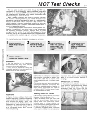 7
7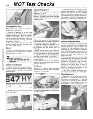 8
8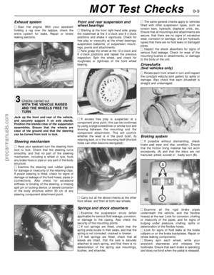 9
9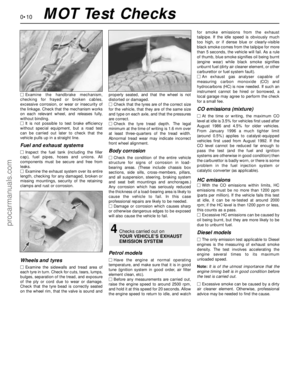 10
10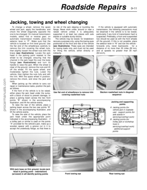 11
11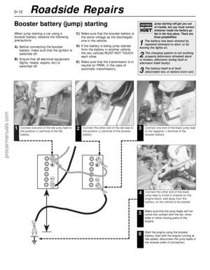 12
12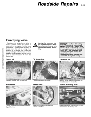 13
13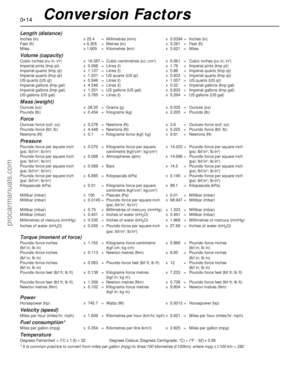 14
14 15
15 16
16 17
17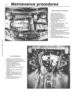 18
18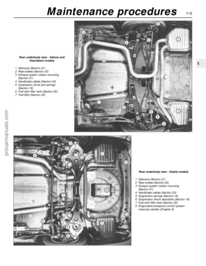 19
19 20
20 21
21 22
22 23
23 24
24 25
25 26
26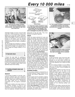 27
27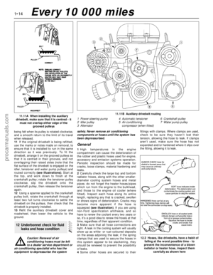 28
28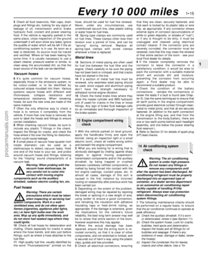 29
29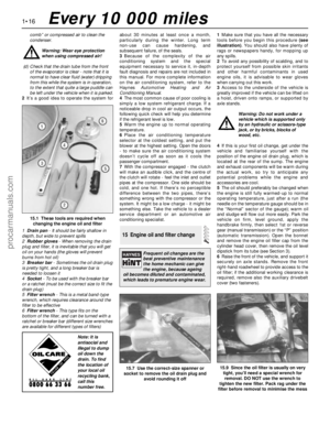 30
30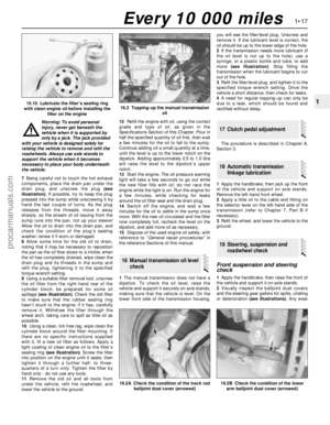 31
31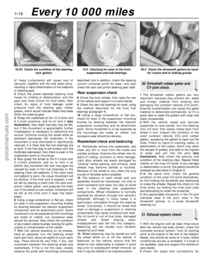 32
32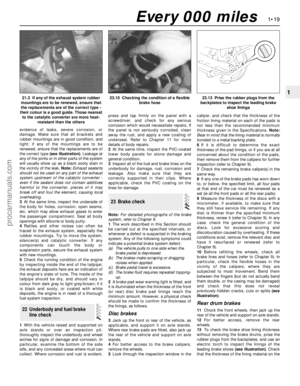 33
33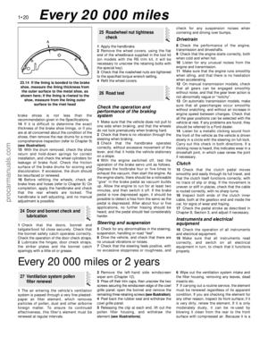 34
34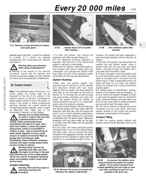 35
35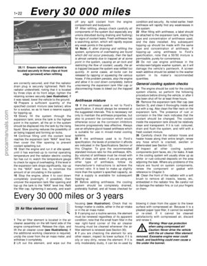 36
36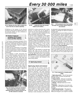 37
37 38
38 39
39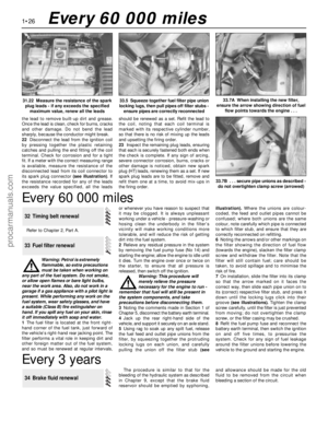 40
40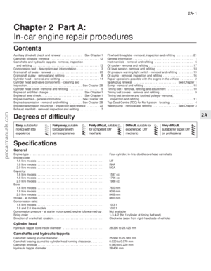 41
41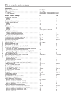 42
42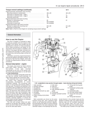 43
43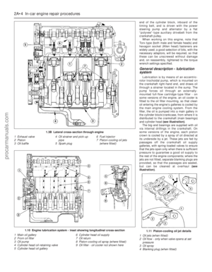 44
44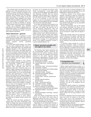 45
45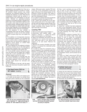 46
46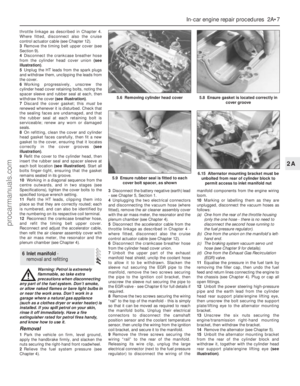 47
47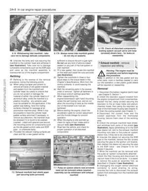 48
48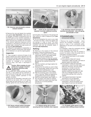 49
49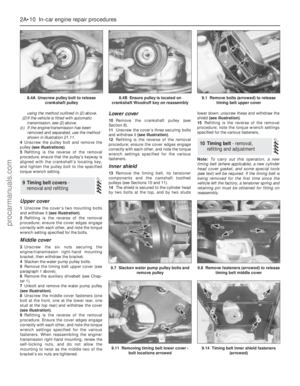 50
50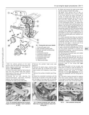 51
51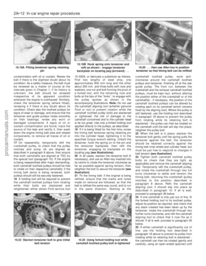 52
52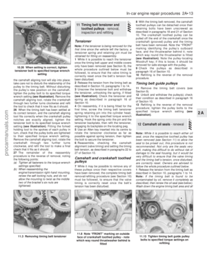 53
53 54
54 55
55 56
56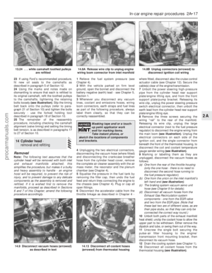 57
57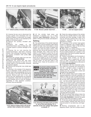 58
58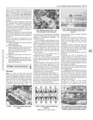 59
59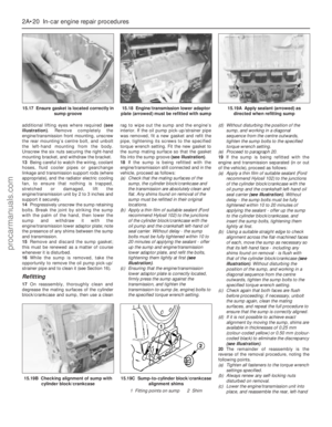 60
60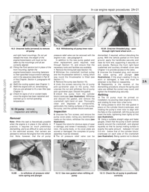 61
61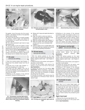 62
62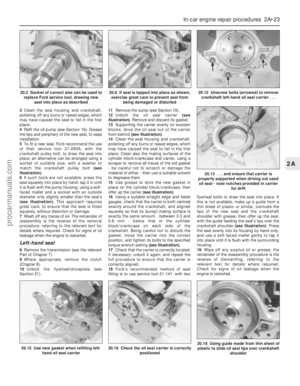 63
63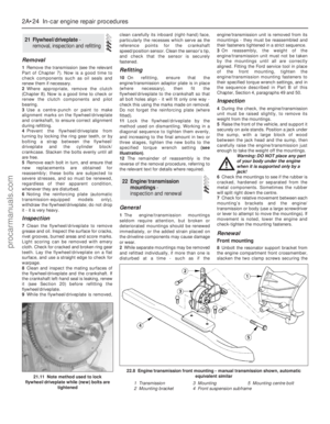 64
64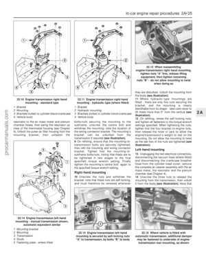 65
65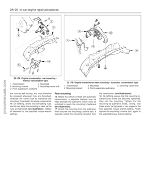 66
66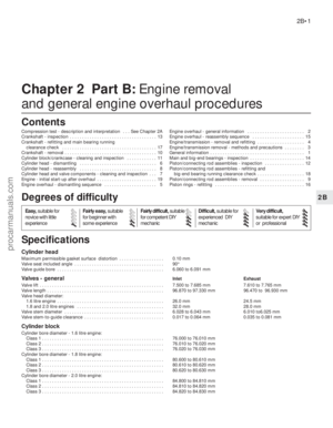 67
67 68
68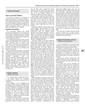 69
69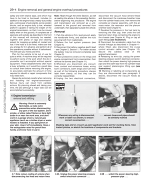 70
70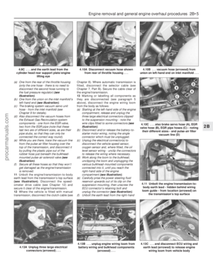 71
71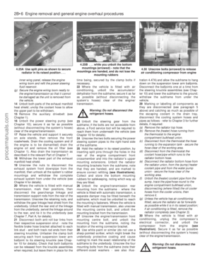 72
72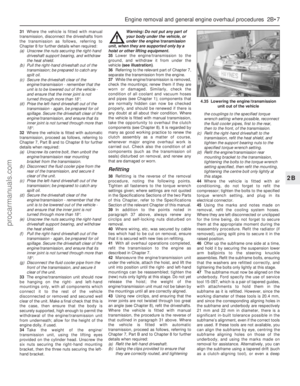 73
73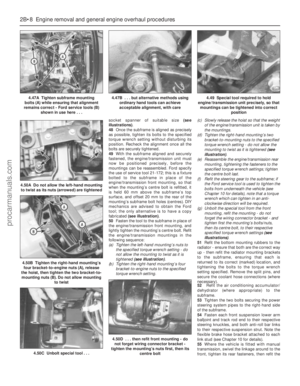 74
74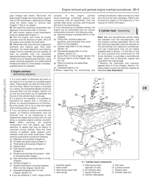 75
75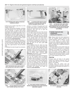 76
76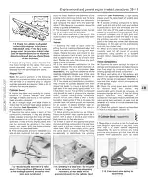 77
77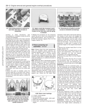 78
78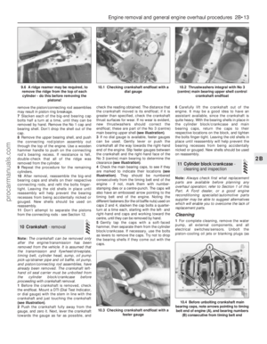 79
79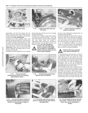 80
80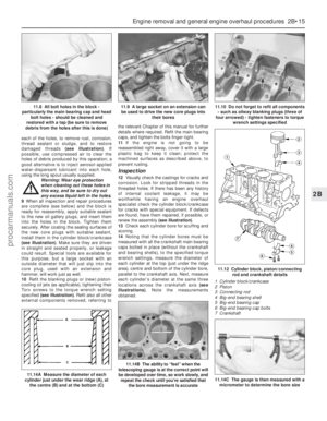 81
81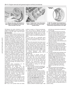 82
82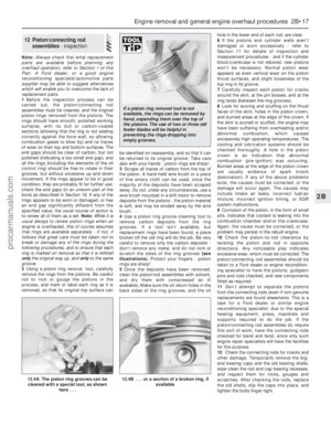 83
83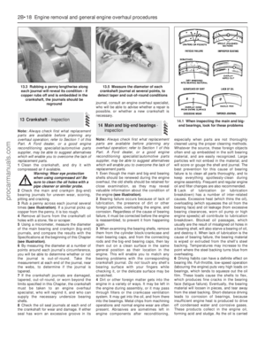 84
84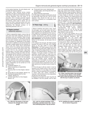 85
85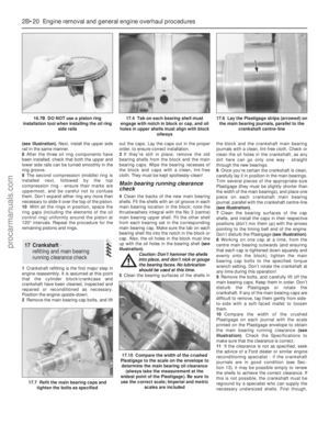 86
86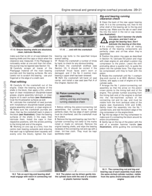 87
87 88
88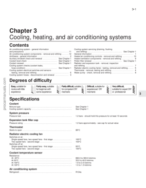 89
89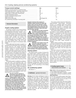 90
90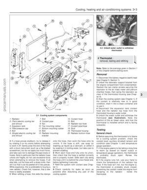 91
91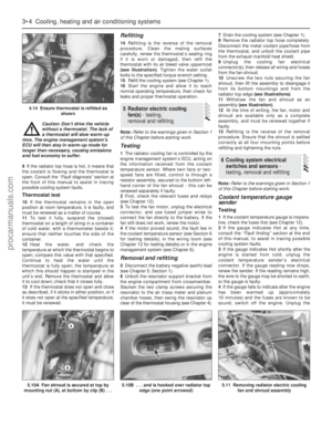 92
92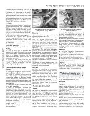 93
93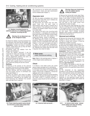 94
94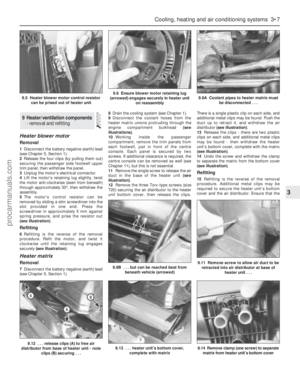 95
95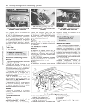 96
96 97
97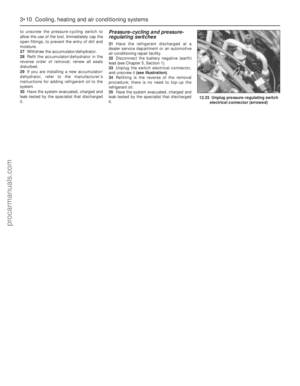 98
98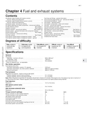 99
99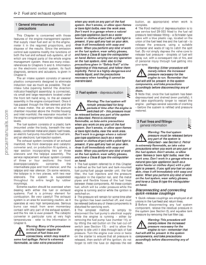 100
100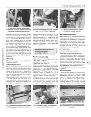 101
101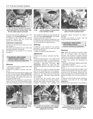 102
102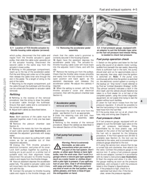 103
103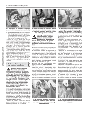 104
104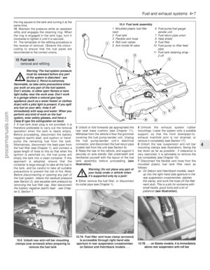 105
105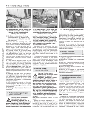 106
106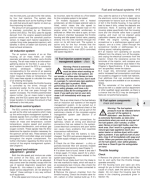 107
107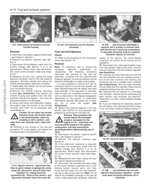 108
108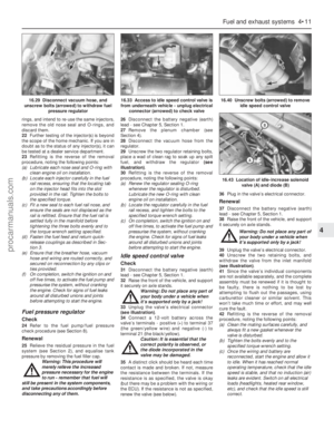 109
109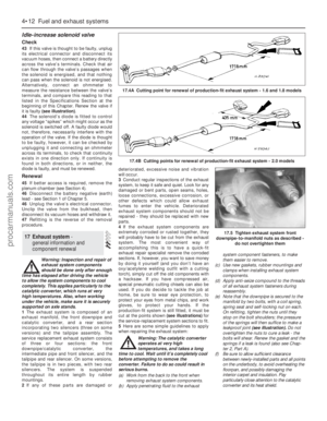 110
110 111
111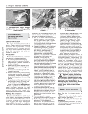 112
112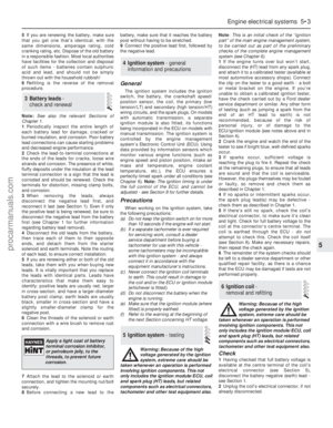 113
113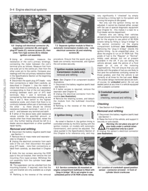 114
114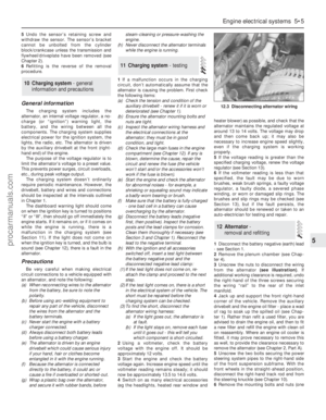 115
115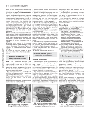 116
116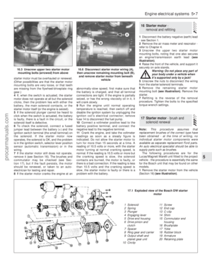 117
117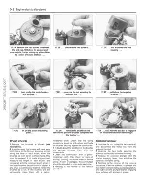 118
118 119
119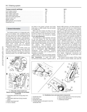 120
120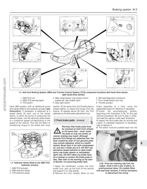 121
121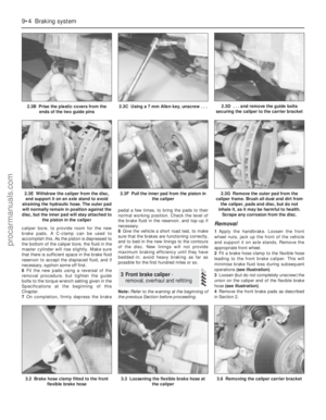 122
122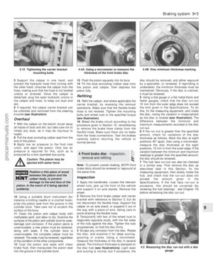 123
123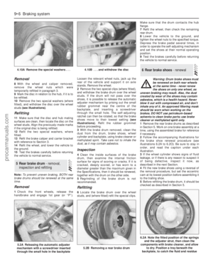 124
124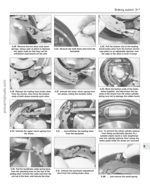 125
125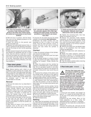 126
126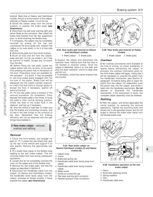 127
127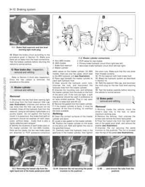 128
128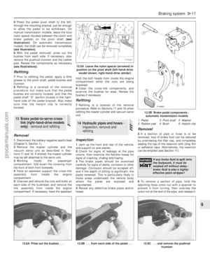 129
129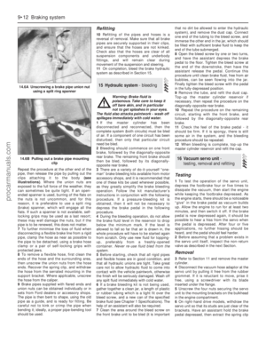 130
130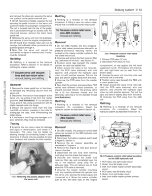 131
131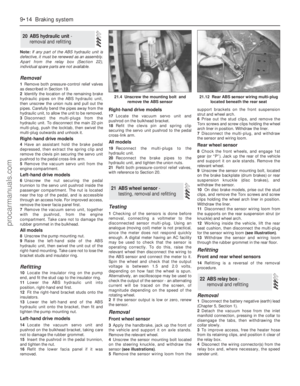 132
132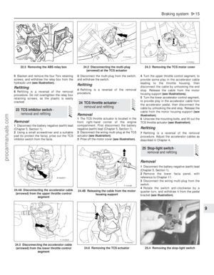 133
133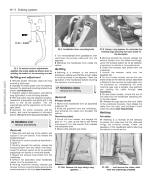 134
134 135
135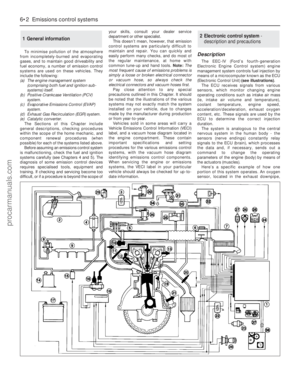 136
136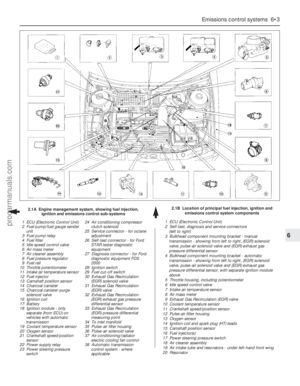 137
137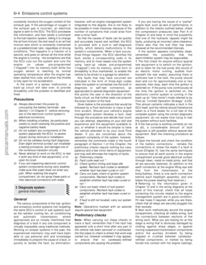 138
138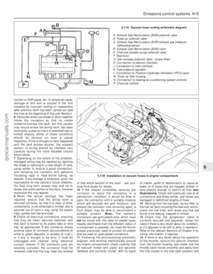 139
139 140
140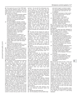 141
141 142
142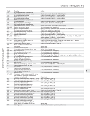 143
143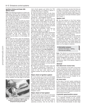 144
144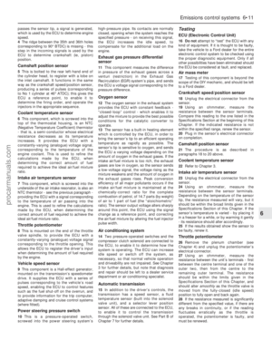 145
145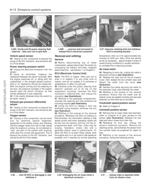 146
146 147
147 148
148 149
149 150
150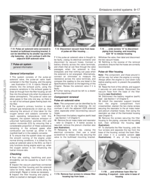 151
151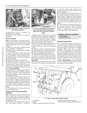 152
152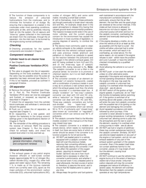 153
153 154
154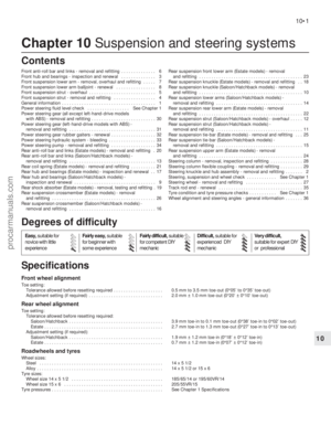 155
155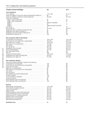 156
156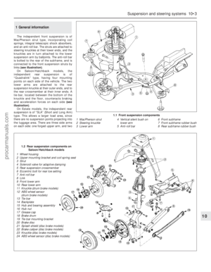 157
157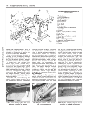 158
158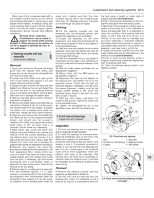 159
159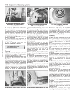 160
160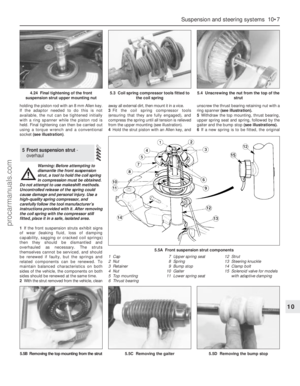 161
161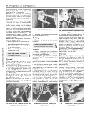 162
162 163
163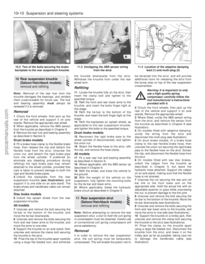 164
164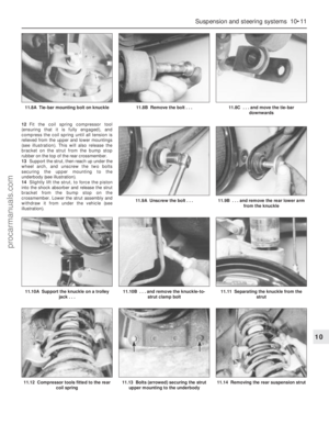 165
165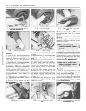 166
166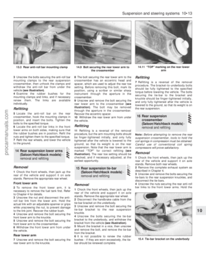 167
167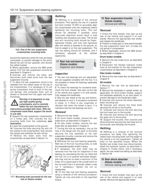 168
168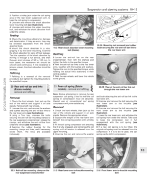 169
169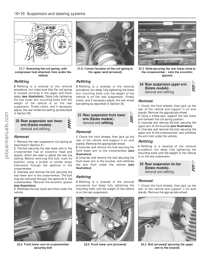 170
170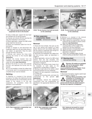 171
171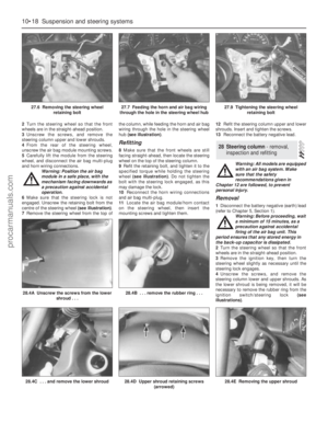 172
172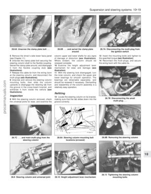 173
173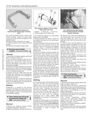 174
174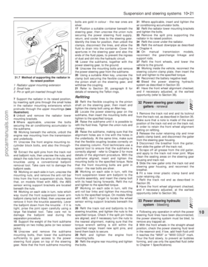 175
175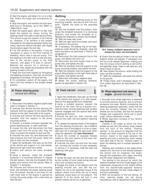 176
176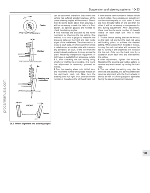 177
177 178
178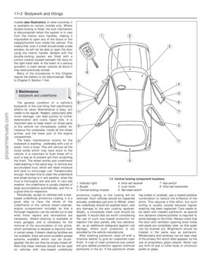 179
179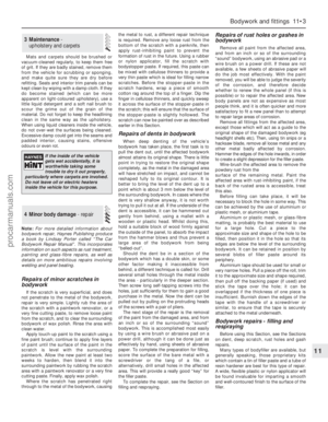 180
180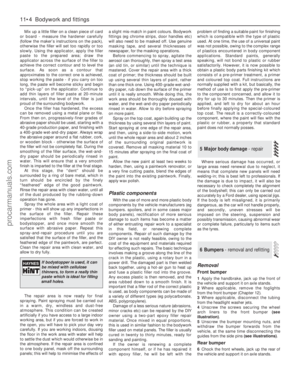 181
181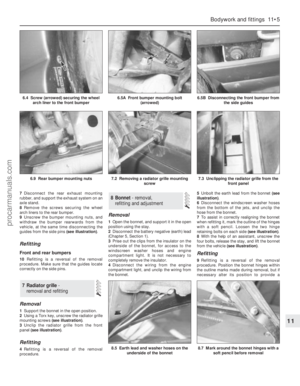 182
182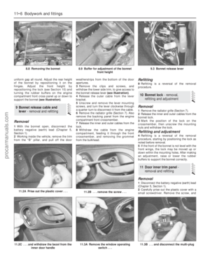 183
183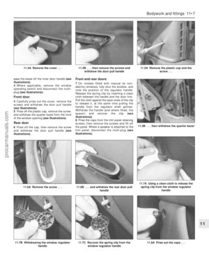 184
184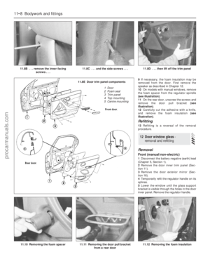 185
185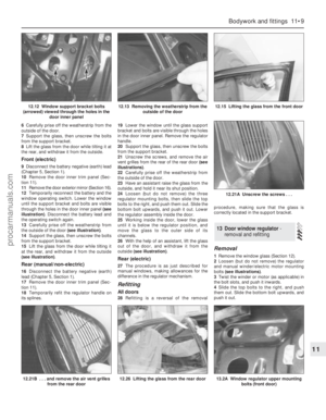 186
186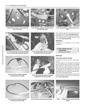 187
187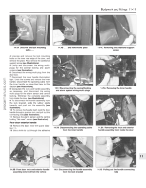 188
188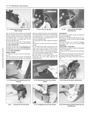 189
189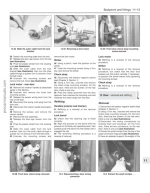 190
190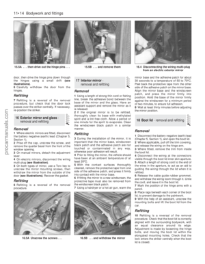 191
191 192
192 193
193 194
194 195
195 196
196 197
197 198
198 199
199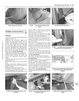 200
200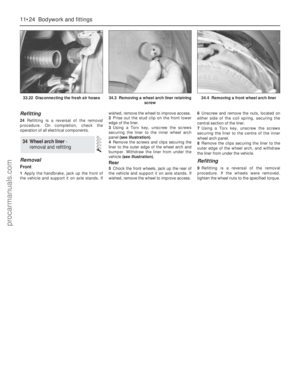 201
201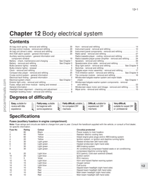 202
202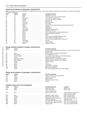 203
203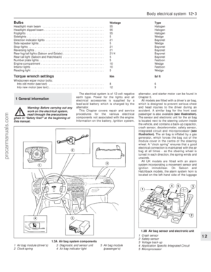 204
204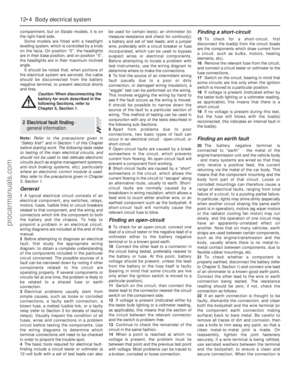 205
205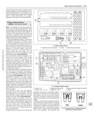 206
206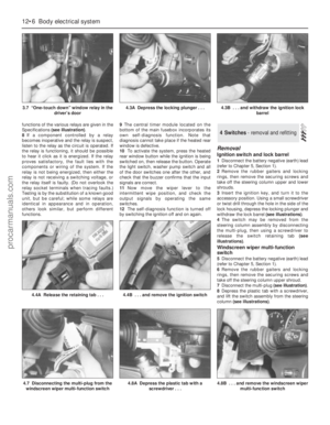 207
207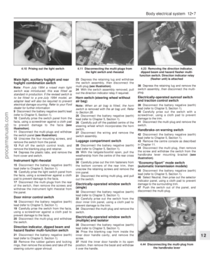 208
208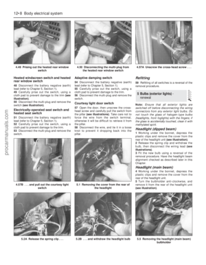 209
209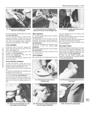 210
210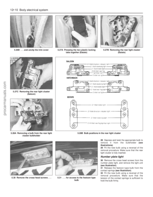 211
211 212
212 213
213 214
214 215
215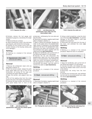 216
216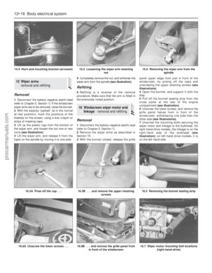 217
217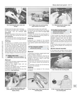 218
218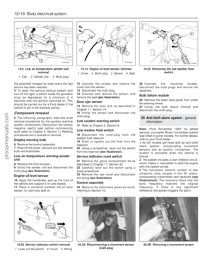 219
219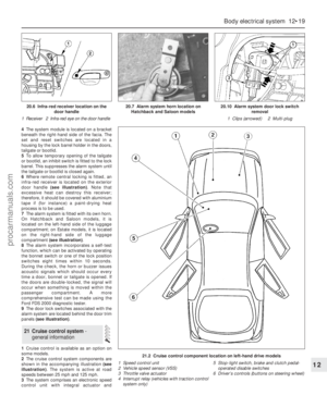 220
220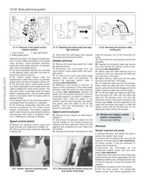 221
221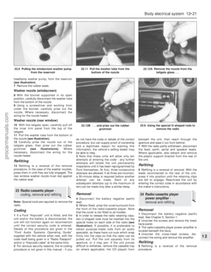 222
222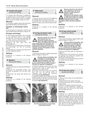 223
223 224
224 225
225 226
226 227
227 228
228 229
229 230
230 231
231 232
232 233
233 234
234 235
235 236
236 237
237 238
238 239
239 240
240 241
241 242
242 243
243 244
244 245
245 246
246 247
247 248
248 249
249 250
250 251
251 252
252 253
253 254
254 255
255 256
256 257
257 258
258 259
259 260
260 261
261 262
262 263
263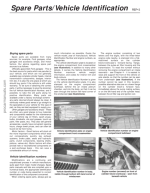 264
264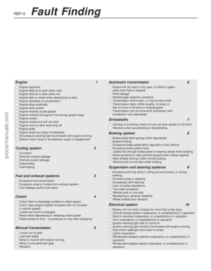 265
265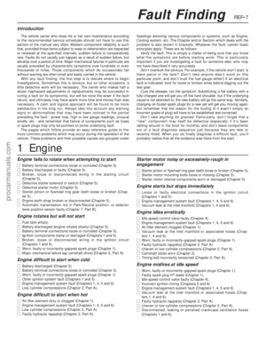 266
266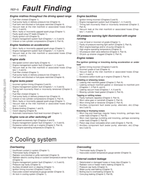 267
267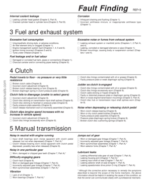 268
268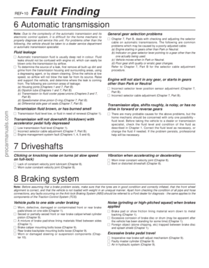 269
269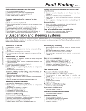 270
270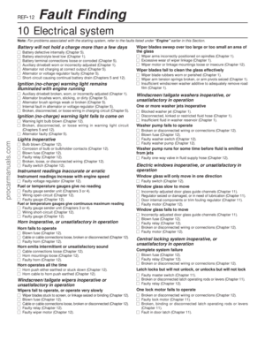 271
271 272
272 273
273 274
274 275
275 276
276 277
277 278
278