Page 137 of 279

Emissions control systems 6•3
6
2.1B Location of principal fuel injection, ignition and
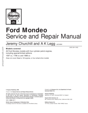
emissions control system components 2.1A Engine management system, showing fuel injection,
ignition and emissions control sub-systems
1 ECU (Electronic Control Unit)
2 Fuel pump/fuel gauge sender
unit
3 Fuel pump relay
4 Fuel filter
5 Idle speed control valve
6 Air mass meter
7 Air cleaner assembly
8 Fuel pressure regulator
9 Fuel rail
10 Throttle potentiometer
11 Intake air temperature sensor
12 Fuel injector
13 Camshaft position sensor
14 Charcoal canister
15 Charcoal canister-purge
solenoid valve
16 Ignition coil
17 Battery
18 Ignition module - only
separate (from ECU) on
vehicles with automatic
transmission
19 Coolant temperature sensor
20 Oxygen sensor
21 Crankshaft speed/position
sensor
22 Power supply relay
23 Power steering pressure
switch24 Air conditioning compressor
clutch solenoid
25 Service connector - for octane
adjustment
26 Self-test connector - for Ford
STAR tester diagnostic
equipment
27 Diagnosis connector - for Ford
diagnostic equipment FDS
2000
28 Ignition switch
29 Fuel cut-off switch
30 Exhaust Gas Recirculation
(EGR) solenoid valve
31 Exhaust Gas Recirculation
(EGR) valve
32 Exhaust Gas Recirculation
(EGR) exhaust gas pressure
differential sensor
33 Exhaust Gas Recirculation
(EGR) pressure differential
measuring point
34 To inlet manifold
35 Pulse-air filter housing
36 Pulse-air solenoid valve
37 Air conditioning/radiator
electric cooling fan control
38 Automatic transmission
control system - where
applicable1 ECU (Electronic Control Unit)
2 Self-test, diagnosis and service connectors
(left to right)
3 Bulkhead component mounting bracket - manual
transmission - showing from left to right, (EGR) solenoid
valve, pulse-air solenoid valve and (EGR) exhaust gas
pressure differential sensor
4 Bulkhead component mounting bracket - automatic
transmission - showing from left to right, (EGR) solenoid
valve, pulse-air solenoid valve and (EGR) exhaust gas
pressure differential sensor, with separate ignition module
above
5 Throttle housing, including potentiometer
6 Idle speed control valve
7 Intake air temperature sensor
8 Air mass meter
9 Exhaust Gas Recirculation (EGR) valve
10 Coolant temperature sensor
11 Crankshaft speed/position sensor
12 Pulse-air filter housing
13 Oxygen sensor
14 Ignition coil and spark plug (HT) leads
15 Camshaft position sensor
16 Fuel injector(s)
17 Power steering pressure switch
18 Air cleaner assembly
19 Air intake tube and resonators - under left-hand front wing
20 Resonator
procarmanuals.com
Page 138 of 279

constantly monitors the oxygen content of the
exhaust gas. If the percentage of oxygen in
the exhaust gas is incorrect, an electrical
signal is sent to the ECU. The ECU processes
this information, and then sends a command
to the fuel injection system, telling it to change
the air/fuel mixture; the end result is an air/fuel
mixture ratio which is constantly maintained
at a predetermined ratio, regardless of driving
conditions. This happens in a fraction of a
second, and goes on almost all the time while
the engine is running - the exceptions are that
the ECU cuts out the system and runs the
engine on values pre-programmed
(“mapped”) into its memory both while the
oxygen sensor is reaching its normal
operating temperature after the engine has
been started from cold, and when the throttle
is fully open for full acceleration.
In the event of a sensor malfunction, a
back-up circuit will take over, to provide
driveability until the problem is identified and
fixed.
Precautions
(a) Always disconnect the power by
uncoupling the battery terminals - see
Section 1 of Chapter 5 - before removing
any of the electronic control system’s
electrical connectors.
(b) When installing a battery, be particularly
careful to avoid reversing the positive and
negative battery leads.
(c) Do not subject any components of the
system (especially the ECU) to severe
impact during removal or installation.
(d) Do not be careless during fault diagnosis.
Even slight terminal contact can invalidate
a testing procedure, and damage one of
the numerous transistor circuits.
(e) Never attempt to work on the ECU, to test
it (with any kind of test equipment), or to
open its cover.
(f) If you are inspecting electronic control
system components during rainy weather,
make sure that water does not enter any
part. When washing the engine
compartment, do not spray these parts or
their electrical connectors with water.
General
The various components of the fuel, ignition
and emissions control systems (not forgetting
the same ECU’s control of sub-systems such
as the radiator cooling fan, air conditioning
and automatic transmission, where
appropriate) are so closely interlinked that
diagnosis of a fault in any one component is
virtually impossible using traditional methods.
Working on simpler systems in the past, the
experienced mechanic may well have been
able to use personal skill and knowledge
immediately to pinpoint the cause of a fault, or
quickly to isolate the fault, by elimination;however, with an engine management system
integrated to this degree, this is not likely to
be possible in most instances, because of the
number of symptoms that could arise from
even a minor fault.
So that the causes of faults can be quickly
and accurately traced and rectified, the ECU
is provided with a built-in self-diagnosis
facility, which detects malfunctions in the
system’s components. When a fault occurs,
three things happen: the ECU identifies the
fault, stores a corresponding code in its
memory, and (in most cases) runs the system
using back-up values pre-programmed
(“mapped”) into its memory; some form of
driveability is thus maintained, to enable the
vehicle to be driven to a garage for attention.
Any faults that may have occurred are
indicated in the form of three-digit codes
when the system is connected (via the built-in
diagnosis or self-test connectors, as
appropriate) to special diagnostic equipment -
this points the user in the direction of the
faulty circuit, so that further tests can pinpoint
the exact location of the fault.
Given below is the procedure that would be
followed by a Ford technician to trace a fault
from scratch. Should your vehicle’s engine
management system develop a fault, read
through the procedure and decide how much
you can attempt, depending on your skill and
experience and the equipment available to
you, or whether it would be simpler to have
the vehicle attended to by your local Ford
dealer. If you are concerned about the
apparent complexity of the system, however,
remember the comments made in the fourth
paragraph of Section 1 of this Chapter; the
preliminary checks require nothing but care,
patience and a few minor items of equipment,
and may well eliminate the majority of faults.
(a) Preliminary checks
(b) Fault code read-out *
(c) Check ignition timing and base idle
speed. Recheck fault codes to establish
whether fault has been cured or not *
(d) Carry out basic check of ignition system
components. Recheck fault codes to
establish whether fault has been cured or
not *
(e) Carry out basic check of fuel system
components. Recheck fault codes to
establish whether fault has been cured or
not *
(f) If fault is still not located, carry out system
test *
Note:Operations marked with an asterisk
require special test equipment.
Preliminary checks
Note:When carrying out these checks to
trace a fault, remember that if the fault has
appeared only a short time after any part of
the vehicle has been serviced or overhauled,
the first place to check is where that work was
carried out, however unrelated it may appear,
to ensure that no carelessly-refitted
components are causing the problem.If you are tracing the cause of a “partial”
engine fault, such as lack of performance, in
addition to the checks outlined below, check
the compression pressures (see Part A of
Chapter 2) and bear in mind the possibility
that one of the hydraulic tappets might be
faulty, producing an incorrect valve clearance.
Check also that the fuel filter has been
renewed at the recommended intervals.
If the system appears completely dead,
remember the possibility that the
alarm/inhibitor system may be responsible.
1The first check for anyone without special
test equipment is to switch on the ignition,
and to listen for the fuel pump (the sound of
an electric motor running, audible from
beneath the rear seats); assuming there is
sufficient fuel in the tank, the pump should
start and run for approximately one or two
seconds, then stop, each time the ignition is
switched on. If the pump runs continuously all
the time the ignition is switched on, the
electronic control system is running in the
back-up (or “limp-home”) mode referred to by
Ford as “Limited Operation Strategy” (LOS).
This almost certainly indicates a fault in the
ECU itself, and the vehicle should therefore be
taken to a Ford dealer for a full test of the
complete system using the correct diagnostic
equipment; do not waste time trying to test
the system without such facilities.
2If the fuel pump is working correctly (or not
at all), a considerable amount of fault
diagnosis is still possible without special test
equipment. Start the checking procedure as
follows.
3Open the bonnet and check the condition
of the battery connections - remake the
connections or renew the leads if a fault is
found (Chapter 5). Use the same techniques
to ensure that all earth points in the engine
compartment provide good electrical contact
through clean, metal-to-metal joints, and that
all are securely fastened. (In addition to the
earth connection at the engine lifting eye and
that from the transmission to the
body/battery, there is one earth connection
behind each headlight assembly, and one
below the power steering fluid reservoir.)
4Referring to the information given in
Chapter 12 and in the wiring diagrams at the
back of this manual, check that all fuses
protecting the circuits related to the engine
management system are in good condition.
Fit new fuses if required; while you are there,
check that all relays are securely plugged into
their sockets.
5Next work methodically around the engine
compartment, checking all visible wiring, and
the connections between sections of the
wiring loom. What you are looking for at this
stage is wiring that is obviously damaged by
chafing against sharp edges, or against
moving suspension/transmission components
and/or the auxiliary drivebelt, by being
trapped or crushed between carelessly-
refitted components, or melted by being
forced into contact with hot engine castings,
3 Diagnosis system -
general information
6•4 Emissions control systems
procarmanuals.com
Page 139 of 279

coolant or EGR pipes, etc. In almost all cases,
damage of this sort is caused in the first
instance by incorrect routing on reassembly
after previous work has been carried out (see
the note at the beginning of this sub-Section).
6Obviously wires can break or short together
inside the insulation so that no visible
evidence betrays the fault, but this usually
only occurs where the wiring loom has been
incorrectly routed so that it is stretched taut or
kinked sharply; either of these conditions
should be obvious on even a casual
inspection. If this is thought to have happened
and the fault proves elusive, the suspect
section of wiring should be checked very
carefully during the more detailed checks
which follow.
7Depending on the extent of the problem,
damaged wiring may be repaired by rejoining
the break or splicing-in a new length of wire,
using solder to ensure a good connection,
and remaking the insulation with adhesive
insulating tape or heat-shrink tubing, as
desired. If the damage is extensive, given the
implications for the vehicle’s future reliability,
the best long-term answer may well be to
renew that entire section of the loom, however
expensive this may appear.
8When the actual damage has been
repaired, ensure that the wiring loom is
rerouted correctly, so that it is clear of other
components, is not stretched or kinked, and is
secured out of harm’s way using the plastic
clips, guides and ties provided.
9Check all electrical connectors, ensuring
that they are clean, securely fastened, and
that each is locked by its plastic tabs or wire
clip, as appropriate. If any connector shows
external signs of corrosion (accumulations of
white or green deposits, or streaks of “rust”),
or if any is thought to be dirty, it must be
unplugged and cleaned using electrical
contact cleaner. If the connector pins are
severely corroded, the connector must be
renewed; note that this may mean the renewalof that entire section of the loom - see your
local Ford dealer for details.
10If the cleaner completely removes the
corrosion to leave the connector in a
satisfactory condition, it would be wise to
pack the connector with a suitable material
which will exclude dirt and moisture, and
prevent the corrosion from occurring again; a
Ford dealer may be able to recommend a
suitable product. Note:The system’s
connectors use gold-plated pins, which must
notbe mixed with the older tin-plated types
(readily identifiable from the different colour) if
a component is renewed, nor must the lithium
grease previously used to protect tin-plated
pins be used on gold-plated connectors.
11Following the accompanying schematic
diagram, and working methodically around
the engine compartment, check carefully that
all vacuum hoses and pipes are securely
fastened and correctly routed, with no signsof cracks, splits or deterioration to cause air
leaks, or of hoses that are trapped, kinked, or
bent sharply enough to restrict air flow (see
illustrations). Check with particular care at all
connections and sharp bends, and renew any
damaged or deformed lengths of hose.
12Working from the fuel tank, via the filter, to
the fuel rail (and including the feed and return),
check the fuel lines, and renew any that are
found to be leaking, trapped or kinked.
13Check that the accelerator cable is
correctly secured and adjusted; renew the
cable if there is any doubt about its condition,
or if it appears to be stiff or jerky in operation.
Refer to the relevant Sections of Chapter 4 for
further information, if required.
14If there is any doubt about the operation
of the throttle, remove the plenum chamber
from the throttle housing, and check that the
throttle valve moves smoothly and easily from
the fully-closed to the fully-open position and
Emissions control systems 6•5
6
3.11A Vacuum hose routing schematic diagram
A Exhaust Gas Recirculation (EGR) solenoid valve
B Pulse-air solenoid valve
C Exhaust Gas Recirculation (EGR) exhaust gas pressure
differential sensor
D Exhaust Gas Recirculation (EGR) valve
E Charcoal canister-purge solenoid valve
F Restrictor
G Idle-increase solenoid valve - where fitted
H Connection to plenum chamber
J Connection to inlet manifold
K Fuel pressure regulator
L Connection to Positive Crankcase Ventilation (PCV) valve
M Pulse-air filter housing
N Connection to heating/air conditioning system controls
P Charcoal canister
3.11B Installation of vacuum hoses in engine compartment
procarmanuals.com
Page 140 of 279

back again, as an assistant depresses the
accelerator pedal. If the valve shows any sign
of stiffness, sticking or otherwise-inhibited
movement (and the accelerator cable is
known from the previous check to be in good
condition), spray the throttle linkage with
penetrating lubricant, allow time for it to work,
and repeat the check; if no improvement is
obtained, the complete throttle housing must
be renewed (Chapter 4).
15Unclip the air cleaner cover, and check
that the air filter element and the crankcase
ventilation system filter are not clogged or
soaked. (A clogged air filter will obstruct the
intake air flow, causing a noticeable effect on
engine performance; a clogged crankcase
ventilation system filter will inhibit crankcase
“breathing”). Renew or clean the filter(s) as
appropriate; refer to the relevant Sections of
Chapter 1 for further information, if required.
Before refitting the air cleaner cover, check
that the air intake (located under the front left-
hand wing, opening behind the direction
indicator/headlight assembly) is clear. It
should be possible to blow through the intake,
or to probe it (carefully) as far as the rear of
the direction indicator light.
16Start the engine and allow it to idle.
Note:Working in the engine compartment
while the engine is running requires great care
if the risk of personal injury is to be avoided;
among the dangers are burns from contact
with hot components, or contact with moving
components such as the radiator cooling fan
or the auxiliary drivebelt. Refer to “Safety
first!” at the front of this manual before
starting, and ensure that your hands, and long
hair or loose clothing, are kept well clear of hot
or moving components at all times.
17Working from the air intake junction at the
inner wing panel, via the air cleaner assembly
and air mass meter, to the resonator, plenum
chamber, throttle housing and inlet manifold
(and including the various vacuum hoses and
pipes connected to these), check for air leaks.
Usually, these will be revealed by sucking or
hissing noises, but minor leaks may be traced
by spraying a solution of soapy water on to
the suspect joint; if a leak exists, it will be
shown by the change in engine note and the
accompanying air bubbles (or sucking-in of
the liquid, depending on the pressure
difference at that point). If a leak is found at
any point, tighten the fastening clamp and/or
renew the faulty components, as applicable.
18Similarly, work from the cylinder head, via
the manifold (and not forgetting the related
EGR and pulse-air system components) to the
tailpipe, to check that the exhaust system is
free from leaks. The simplest way of doing
this, if the vehicle can be raised and
supported safely and with complete security
while the check is made, is to temporarily
block the tailpipe while listening for the sound
of escaping exhaust gases; any leak should
be evident. If a leak is found at any point,
tighten the fastening clamp bolts and/or nuts,
renew the gasket, and/or renew the faultysection of the system, as necessary, to seal
the leak.
19It is possible to make a further check of
the electrical connections by wiggling each
electrical connector of the system in turn as
the engine is idling; a faulty connector will be
immediately evident from the engine’s
response as contact is broken and remade. A
faulty connector should be renewed to ensure
the future reliability of the system; note that
this may mean the renewal of that entire
section of the loom - see your local Ford
dealer for details.
20Switch off the engine. If the fault is not yet
identified, the next step is to check the
ignition voltages, using an engine analyser
with an oscilloscope - without such
equipment, the only tests possible are to
remove and check each spark plug in turn, to
check the spark plug (HT) lead connections
and resistances, and to check the
connections and resistances of the ignition
coil. Refer to the relevant Sections of
Chapters 1 and 5.
21The final step in these preliminary checks
would be to use an exhaust gas analyser to
measure the CO level at the exhaust tailpipe.This check cannot be made without special
test equipment - see your local Ford dealer for
details.
Fault code read-out
22As noted in the general comments at the
beginning of this Section, the preliminary
checks outlined above should eliminate the
majority of faults from the engine
management system. If the fault is not yet
identified, the next step is to connect a fault
code reader to the ECU, so that its self-
diagnosis facility can be used to identify the
faulty part of the system; further tests can
then be made to identify the exact cause of
the fault.
23In their basic form, fault code readers are
simply hand-held electronic devices, which
take data stored within an ECU’s memory and
display it when required as two- or three-digit
fault codes. The more sophisticated versions
now available can also control sensors and
actuators, to provide more effective testing;
some can store information, so that a road
test can be carried out, and any faults
encountered during the test can be displayed
afterwards.
6•6 Emissions control systems
3.26 Location and terminal identification of engine management system self-test,
diagnosis and service connectors
1 Power steering fluid reservoir
2 Diagnosis connector - for Ford diagnostic equipment FDS 2000
3 Self-test connector - for fault code read-out - pin 17 is output terminal, pin 48 is input
terminal, pin 40/60 is earth
4 Service connector - for octane adjustment
5 Plug-in bridge - to suit 95 RON fuel
procarmanuals.com
Page 141 of 279
 tester; most Ford
dealers should have such equipment, and the
staff trained to use it effectively. The only
alternatives are as foll")
24Ford specify the use of their STAR (Self-
Test Automatic Readout) tester; most Ford
dealers should have such equipment, and the
staff trained to use it effectively. The only
alternatives are as follows:
(a) To obtain one of those proprietary readers
which can interpret EEC-IV three-digit
codes - at present, such readers are too
expensive for the DIY enthusiast, but are
becoming more popular with smaller
specialist garages.
(b) To use an analogue voltmeter, whereby
the stored codes are displayed as sweeps
of the voltmeter needle. This option limits
the operator to a read-out of any codes
stored - ie, there is no control of sensors
and/or actuators - but can still be useful in
pinpointing the faulty part of the engine
management system. The display is
interpreted as follows. Each code
(whether fault code or
command/separator) is marked by a
three-to-four second pause - code “538”
would therefore be shown as long (3 to
4 seconds) pause, five fast sweeps of the
needle, slight (1 second) pause, three fast
sweeps, slight pause, eight fast sweeps,
long pause.
(c) Owners without access to such
equipment must take the vehicle to a Ford
dealer, or to an expert who has similar
equipment and the skill to use it.
25Because of the variations in the design of
fault code readers, it is not possible to give
exact details of the sequence of tests; the
manufacturer’s instructions must be followed,
in conjunction with the codes given below.
The following ten paragraphs outline the
procedure to be followed using a version of
the Ford STAR tester, to illustrate the general
principles, as well as notes to guide the owner
using only a voltmeter.
26The vehicle must be prepared by applying
the handbrake, switching off the air
conditioning (where fitted) and any other
electrical loads (lights, heated rear window,
etc), then selecting neutral (manual
transmission) or the “P” position (automatic
transmission). Where the engine is required to
be running, it must be fully warmed-up to
normal operating temperature before the test
is started. Using any adaptors required,
connect the fault code reader to the system
via the (triangular, three-pin) self-test
connector on the right-hand end of the engine
compartment bulkhead (see illustration). If a
voltmeter is being used, connect its positive
lead to the battery positive terminal, and its
negative lead to the self-test connector’s
output terminal, pin 17. Have a pen and paper
ready to write down the codes displayed.
27Set the tester in operation. For the Ford
STAR tester, a display check will be carried
out and the test mode requirements must be
entered. If a voltmeter is being used, connect
a spare length of wire to earth the self-test
connector’s input terminal, pin 48. Be very
careful to ensure that you earth the correctterminal - the one with the white/green wire.
The first part of the test starts, with the
ignition switched on, but with the engine off.
On pressing the “Mem/test” button, the tester
displays “TEST” and the ready code “000”,
followed by a command code “010” - the
accelerator pedal must be fully depressed
within 10 seconds of the command code
appearing, or fault codes “576” or “577” will
appear when they are called up later. If a
voltmeter is being used, code “000” will not
appear (except perhaps as a flicker of the
needle) and “010” will appear as a single
sweep - to ensure correct interpretation of the
display, watch carefully for the interval
between the end of one code and the
beginning of the next, otherwise you will
become confused and misinterpret the read-
out.
28The tester will then display the codes for
any faults in the system at the time of the test.
Each code is repeated once; if no faults are
present, code “111” will be displayed. If a
voltmeter is being used, the pause between
repetitions will vary according to the
equipment in use and the number of faults in
the system, but was found to be
approximately 3 to 4 seconds - it may be
necessary to start again, and to repeat the
read-out until you are familiar with what you
are seeing.
29Next the tester will display code “010”
(now acting as a separator), followed by the
codes for any faults stored in the ECU’s
memory; if no faults were stored, code “111”
will be displayed.
30When prompted by the tester, the
operator must next depress the accelerator
pedal fully; the tester then checks several
actuators. Further test modes include a
“wiggle test” facility, whereby the operator
can check the various connectors as
described in paragraph 19 above (in this case,
any fault will be logged and the appropriate
code will be displayed), a facility for recalling
codes displayed, and a means for clearing the
ECU’s memory at the end of the test
procedure when any faults have been
rectified.
31The next step when using the Ford STAR
tester is to conduct a test with the engine
running. With the tester set in operation (see
paragraph 26 above) the engine is started and
allowed to idle. On pressing the “Mem/test”
button, the tester displays “TEST”, followed
by one of two codes, as follows.
32If warning code “998” appears, followed
by the appropriate fault code, switch off and
check as indicated the coolant temperature
sensor, the intake air temperature sensor, the
air mass meter, the throttle potentiometer
and/or their related circuits, then restart the
test procedure.
33If command code “020” appears, carry
out the following procedure within ten
seconds:
(a) Depress the brake pedal fully.
(b) Turn the steering to full-lock (either way)and centre it again, to produce a signal
from the power steering pressure switch -
if no signal is sent, fault code “521” will
be displayed.
(c) If automatic transmission is fitted, switch
the overdrive cancel button on and off,
then do the same for the
“Economy/Sport” mode switch.
(d) Wait for separator code “010” to be
displayed, then within 10 seconds,
depress the accelerator pedal fully,
increasing engine speed rapidly above
3000 rpm - release the pedal.
34Any faults found in the system will be
logged and displayed. Each code is repeated
once; if no faults are present, code “111” will
be displayed.
35When the codes have been displayed for
all faults logged, the ECU enters its “Service
Adjustment Programme”, as follows:
(a) The programme lasts for 2 minutes.
(b) The idle speed control valve is
deactivated, and the idle speed is set to
its pre-programmed (unregulated) value. If
the appropriate equipment is connected,
the base idle speed can be checked
(note, however, that it is not adjustable).
(c) The ignition timing can be checked if a
timing light is connected (note, however,
that it is not adjustable).
(d) Pressing the accelerator pedal fully at any
time during this period will execute a
cylinder balance test. Each injector in turn
is switched off, and the corresponding
decrease in engine speed is logged -
code “090” will be displayed if the test is
successful.
(e) At the end of the 2 minutes, the
completion of the programme is shown
by the engine speed briefly rising, then
returning to normal idling speed as
the idle speed control valve is
reactivated.
36As with the engine-off test, further test
modes include a “wiggle test” facility,
whereby the operator can check the various
connectors as described in paragraph 19
above (in this case, any fault will be logged
and the appropriate code will be displayed), a
facility for recalling codes displayed, and a
means for clearing the ECU’s memory at the
end of the test procedure when any faults
have been rectified. If equipment other than
the Ford STAR tester is used, the ECU’s
memory can be cleared by disconnecting the
battery - if this is not done, the code will
reappear with any other codes in the event of
subsequent trouble, but remember that other
systems with memory (such as the clock and
audio equipment) will also be affected. Should
it become necessary to disconnect the
battery during work on any other part of the
vehicle, first check to see if any fault codes
have been logged.
37Given overleaf are the possible codes,
their meanings, and where relevant, the action
to be taken as a result of a code being
displayed.
Emissions control systems 6•7
6
procarmanuals.com
Page 142 of 279

6•8 Emissions control systems
Code Meaning Action
000 Ready for test -
010 Command/separator code Depress accelerator pedal fully, then release
020 Command code Depress brake pedal fully, then release
10 Cylinder No 1 low During cylinder balance test
20 Cylinder No 2 low During cylinder balance test
30 Cylinder No 3 low During cylinder balance test
40 Cylinder No 4 low During cylinder balance test
90 Cylinder balance test successful -
111 No faults found -
112 to 114 Intake air temperature sensor Check component (Section 4 of this Chapter)116 to 118 Coolant temperature sensor - normal If fault still exists on reaching normal operating temperature, check
operating temperature not reached component (Chapter 3)
121 to 125 Throttle potentiometer Check component (Section 4 of this Chapter)129 Incorrect response from air mass
meter while conducting test Repeat test
136, 137 Oxygen sensor Check component (Section 4 of this Chapter)
139 Oxygen sensor Check component (Section 4 of this Chapter)
144 Oxygen sensor Check component (Section 4 of this Chapter)
157 to 159 Air mass meter Check component (Section 4 of this Chapter)
167 Incorrect response from throttle
potentiometer while conducting test Repeat test
171 Oxygen sensor Check component (Section 4 of this Chapter)
172 Oxygen sensor - mixture too weak Check component (Section 4 of this Chapter)
173 Oxygen sensor - mixture too rich Check component (Section 4 of this Chapter)
174, 175 Oxygen sensor Check component (Section 4 of this Chapter)
176 Oxygen sensor - mixture too weak Check component (Section 4 of this Chapter)
177 Oxygen sensor - mixture too rich Check component (Section 4 of this Chapter)
178 Oxygen sensor Check component (Section 4 of this Chapter)
179 Fuel system - mixture too weak Check EGR valve (Section 6 of this Chapter)
181 Fuel system - mixture too rich Check EGR valve (Section 6 of this Chapter)
182 Idle mixture too weak Check idle speed control valve (Chapter 4)
183 Idle mixture too rich If mixture OK, check fuel system (see below)
184, 185 Air mass meter Check component (Section 4 of this Chapter)
186 Injector opening time (pulse width) too long Carry out system test (see below)
187 Injector opening time (pulse width) too short Carry out system test (see below)
188 Oxygen sensor - mixture too weak Check component (Section 4 of this Chapter)
189 Oxygen sensor - mixture too rich Check component (Section 4 of this Chapter)191 Idle mixture too weak Check EGR valve (Section 6 of this Chapter) and idle speed control valve
(Chapter 4)
192 Idle mixture too rich Check EGR valve (Section 6 of this Chapter) and idle speed control valve
(Chapter 4)
194, 195 Oxygen sensor Check component (Section 4 of this Chapter)
211 No ignition signal to ECU Carry out system test (see below)
212 Tachometer circuit Carry out system test (see below)
213 No ignition signal from ECU Carry out system test (see below)
214 Camshaft position sensor Check component (Section 4 of this Chapter)
215 to 217 Ignition coil Carry out system test (see below)
218, 222 Tachometer circuit Carry out system test (see below)
226 ECU/ignition module pulse Carry out system test (see below)
227 Crankshaft speed/position sensor Check component (Chapter 5)
228 Ignition module/ignition coil winding 1 Carry out system test (see below)
229 Ignition module/ignition coil winding 2 Carry out system test (see below)
231 Ignition module/ignition coil winding 3 Carry out system test (see below)
232 Ignition coil primary windings Carry out system test (see below)
233 Ignition module Carry out system test (see below)
234 to 237 Ignition coil primary windings Carry out system test (see below)
238 Ignition module/ignition coil primary windings Carry out system test (see below)
239 No ignition signal to ECU on cranking Carry out system test (see below)
241 Incorrect response from ECU and/or
ignition module while conducting test Repeat test
243 Ignition coil failure Carry out system test (see below)
311 to 316 Pulse-air system Carry out system test (see below)326 EGR system exhaust gas pressure
differential sensor Check component (Section 6 of this Chapter)
procarmanuals.com
Page 143 of 279

328 EGR system solenoid valve Check component (Section 6 of")
Code Meaning Action327 EGR system exhaust gas pressure
differential sensor or solenoid valve Check components (Section 6 of this Chapter)
328 EGR system solenoid valve Check component (Section 6 of this Chapter)
332 EGR valve not opening Check component (Section 6 of this Chapter)
334 EGR system solenoid valve Check component (Section 6 of this Chapter)335 EGR system exhaust gas pressure
differential sensor Check component (Section 6 of this Chapter)
336 Exhaust gas pressure too high Check system (Section 6 of this Chapter)337 EGR system exhaust gas pressure
differential sensor or solenoid valve Check components (Section 6 of this Chapter)
338, 339 Coolant temperature sensor Carry out system test (see below)
341 Service connector earthed Unplug connector and repeat test - reconnect on completion
411 Engine speed too low during test Check for air leaks, then repeat test
412 Engine speed too high during test Check for air leaks, then repeat test
413 to 416 Idle speed control valve Check component (Chapter 4, Section 16)
452 Vehicle speed sensor Check component (Section 4 of this Chapter)
511, 512 ECU memory Check whether battery was disconnected, then check fuse 11 - if fault still
exists, renew ECU (Section 6 of this Chapter)
513 ECU reference voltage Carry out system test (see below)
519, 521 Power steering pressure switch not Check component is fitted and connected, then repeat test - if fault still
operated during test exists, carry out system test (see below)
522, 523 Selector lever position sensor Check component (Chapter 7, Part B)
536 Brake on/off switch not activated
during test Repeat test
538 Operator error during test Repeat test
539 Air conditioning switched on during test Switch off and repeat test
542, 543 Fuel pump circuit Carry out system test (see below)
551 Idle speed control valve circuit Carry out system test (see below)
552 Pulse-air system circuit Carry out system test (see below)
556 Fuel pump circuit Check fuel pump relay - if fault still exists, carry out system test (see below)
558 EGR system solenoid valve circuit Carry out system test (see below)
563 Radiator (high-speed) electric
cooling fan relay and/or circuit Carry out system test (see below)564 Radiator electric cooling fan relay
and/or circuit Carry out system test (see below)
565 Charcoal canister-purge solenoid valve Check component (Section 5 of this Chapter)573 Radiator electric cooling fan relay
and/or circuit Carry out system test (see below)
574 Radiator (high-speed) electric
cooling fan relay and/or circuit Carry out system test (see below)575 Fuel pump and/or fuel cut-off
switch circuits Carry out system test (see below)
576, 577 Accelerator pedal not depressed fully during
test procedure - automatic transmission
kickdown not activated Repeat test
621 Automatic transmission shift solenoid 1 circuit Refer to Chapter 7, Part B
622 Automatic transmission shift solenoid 2 circuit Refer to Chapter 7, Part B
624 Automatic transmission electronic
pressure control solenoid Refer to Chapter 7, Part B
625 Automatic transmission electronic
pressure control solenoid circuit Refer to Chapter 7, Part B
629 Automatic transmission torque
converter clutch solenoid Refer to Chapter 7, Part B
634 Selector lever position sensor circuit Check component (Chapter 7, Part B)
635, 637 Automatic transmission fluid temperature sensor Refer to Chapter 7, Part B
639 Automatic transmission speed sensor Refer to Chapter 7, Part B
645 Automatic transmission 1st speed Refer to Chapter 7, Part B
646 Automatic transmission 2nd speed Refer to Chapter 7, Part B
647 Automatic transmission 3rd speed Refer to Chapter 7, Part B
648 Automatic transmission 4th speed Refer to Chapter 7, Part B
653 Automatic transmission overdrive
cancel button and “Economy/Sport”
mode switch not operated during test Repeat test
998 Warning code Check fault(s) indicated by subsequent code(s)
Emissions control systems 6•9
6
procarmanuals.com
Page 144 of 279

Ignition timing and base idle
speed check
Note:The following procedure is a check only,
essentially of the ECU. Both the ignition timing
and the base idle speed are controlled by the
ECU. The ignition timing is not adjustable at
all; the base idle speed is set in production,
and should not be altered.
38If the fault code read-out (with any checks
resulting from it) has not eliminated the fault,
the next step is to check the ECU’s control of
the ignition timing and the base idle speed.
This task requires the use of a Ford STAR
tester (a proprietary fault code reader can be
used only if it is capable of inducing the ECU
to enter its “Service Adjustment Programme”),
coupled with an accurate tachometer and a
good-quality timing light. Without this
equipment, the task is not possible; the
vehicle must be taken to a Ford dealer for
attention.
39To make the check, apply the handbrake,
switch off the air conditioning (where fitted)
and any other electrical loads (lights, heated
rear window, etc), then select neutral (manual
transmission) or the “P” position (automatic
transmission). Start the engine, and warm it
up to normal operating temperature. The
radiator electric cooling fan must be running
continuously while the check is made; this
should be activated by the ECU, when
prompted by the tester. Switch off the engine,
and connect the test equipment as directed
by the manufacturer - refer to paragraph 26
above for details of STAR tester connection.
40Raise and support the front of the vehicle
securely, and remove the auxiliary drivebelt
cover (see Chapter 1). Emphasise the two
pairs of notches in the inner and outer rims of
the crankshaft pulley, using white paint. Note
that an ignition timing reference mark is not
provided on the pulley - in the normal
direction of crankshaft rotation (clockwise,
seen from the right-hand side of the vehicle)
the first pair of notches are irrelevant to the
vehicles covered in this manual, while the
second pair indicate Top Dead Centre (TDC)
when aligned with the rear edge of the raised
mark on the sump; when checking the ignition
timing, therefore, the (rear edge of the) sumpmark should appear just before the TDC
notches (see Part A of Chapter 2, Section 4,
for further information if required).
41Start the engine and allow it to idle. Work
through the engine-running test procedure
until the ECU enters its “Service Adjustment
Programme” - see paragraph 35 above.
42Use the timing light to check that the
timing marks appear approximately as
outlined above at idle speed. Do not spend
too much time on this check; if the timing
appears to be incorrect, the system may have
a fault, and a full system test must be carried
out (see below) to establish its cause.
43Using the tachometer, check that the
base idle speed is as given in the
Specifications Section of Chapter 4.
44If the recorded speed differs significantly
from the specified value, check for air leaks,
as described in the preliminary checks
(paragraphs 15 to 18 above), or any other
faults which might cause the discrepancy.
45The base idle speed is set in production
by means of an air bypass screw (located in
the front right-hand corner of the throttle
housing) which controls the amount of air that
is allowed to pass through a bypass passage,
past the throttle valve when it is fully closed in
the idle position; the screw is then sealed with
a white tamperproof plug (see illustration). In
service, the idle speed is controlled by the
ECU, which has the ability to compensate for
engine wear, build-up of dirt in the throttle
housing, and other factors which might
require changes in idle speed. The air bypass
screw setting should not, therefore, be
altered. If any alterations are made, a blue
tamperproof plug must be fitted, and the
engine should be allowed to idle for at least
five minutes on completion, so that the ECU
can re-learn its idle values.
46When both checks have been made and
the “Service Adjustment Programme” is
completed, follow the tester instructions to
return to the fault code read-out, and
establish whether the fault has been cured or
not.
Basic check of ignition system
47If the checks so far have not eliminated
the fault, the next step is to carry out a basic
check of the ignition system components,
using an engine analyser with an oscilloscope
- without such equipment, the only tests
possible are to remove and check each spark
plug in turn, to check the spark plug (HT) lead
connections and resistances, and to check
the connections and resistances of the
ignition coil. Refer to the relevant Sections of
Chapters 1 and 5.
Basic check of fuel system
48If the checks so far have not eliminated
the fault, the next step is to carry out a basic
check of the fuel system components.
49Assuming that the preliminary checks
have established that the fuel pump is
operating correctly, that the fuel filter isunlikely to be blocked, and also that there are
no leaks in the system, the next step is to
check the fuel pressure (see Chapter 4). If this
is correct, check the injectors (see Chapter 4)
and the Positive Crankcase Ventilation system
(see Chapter 1).
System test
50The final element of the Ford testing
procedure is to carry out a system test, using
a break-out box - this is a device that is
connected between the ECU and its electrical
connector, so that the individual circuits
indicated by the fault code read-out can be
tested while connected to the system, if
necessary with the engine running. In the case
of many of the system’s components, this
enables their output voltages to be measured
- a more accurate means of testing.
51In addition to the break-out box and the
adaptors required to connect it, several items
of specialist equipment are needed to
complete these tests. This puts them quite
beyond the scope of many smaller dealers, let
alone the DIY owner; the vehicle should be
taken to a Ford dealer for attention.
Note:This Section is concerned principally
with the sensors which give the ECU the
information it needs to control the various
engine management sub-systems - for further
details of those systems and their other
components, refer to the relevant Chapter of
this manual.
General
ECU (Electronic Control Unit)
1This component is the heart of the entire
engine management system, controlling the
fuel injection, ignition and emissions control
systems. It also controls sub-systems such as
the radiator cooling fan, air conditioning and
automatic transmission, where appropriate.
Refer to Section 2 of this Chapter for an
illustration of how it works.
Air mass meter
2This uses a “hot-wire” system, sending the
ECU a constantly-varying (analogue) voltage
signal corresponding to the mass of air
passing into the engine. Since air mass varies
with temperature (cold air being denser than
warm), measuring air mass provides the ECU
with a very accurate means of determining the
correct amount of fuel required to achieve the
ideal air/fuel mixture ratio.
Crankshaft speed/position sensor
3This is an inductive pulse generator bolted
(in a separate bracket) to the cylinder
block/crankcase, to scan the ridges between
36 holes machined in the inboard (right-hand)
face of the flywheel/driveplate. As each ridge
4 Information sensors -
general information, testing,
removal and refitting
6•10 Emissions control systems
3.45 Throttle housing air bypass screw is
sealed on production with a white
tamperproof plug (arrowed)
procarmanuals.com
 1
1 2
2 3
3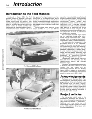 4
4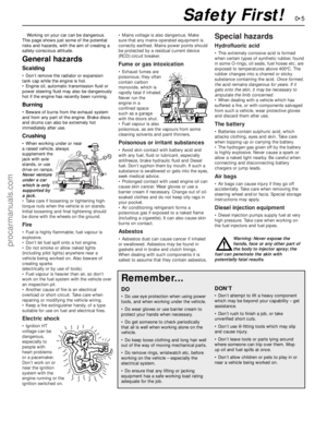 5
5 6
6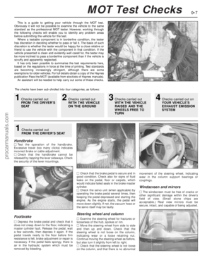 7
7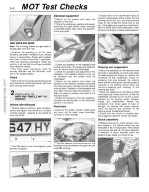 8
8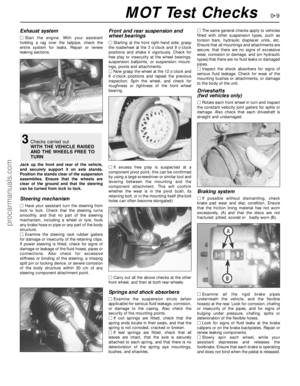 9
9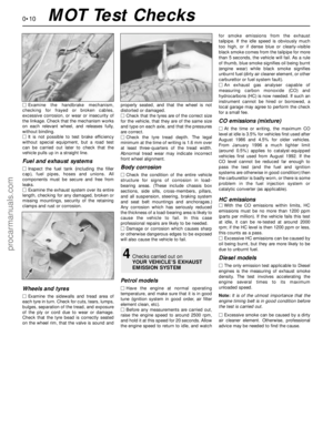 10
10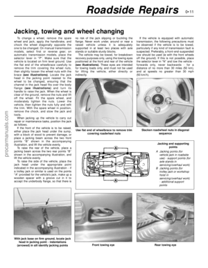 11
11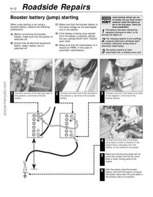 12
12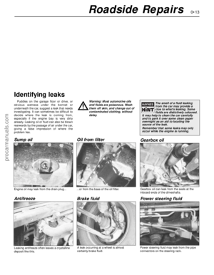 13
13 14
14 15
15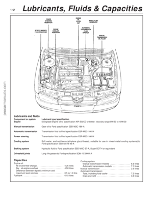 16
16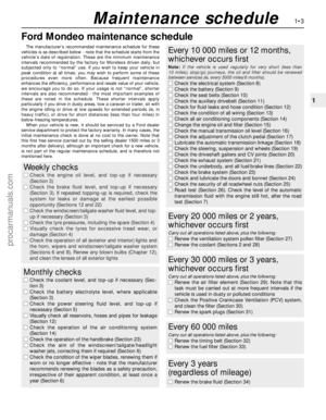 17
17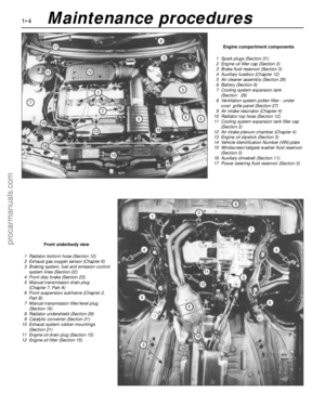 18
18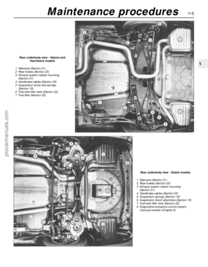 19
19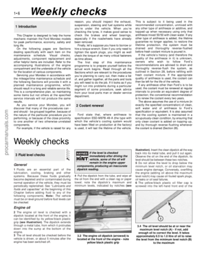 20
20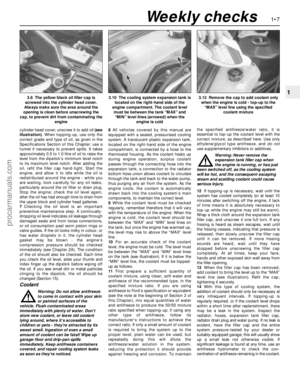 21
21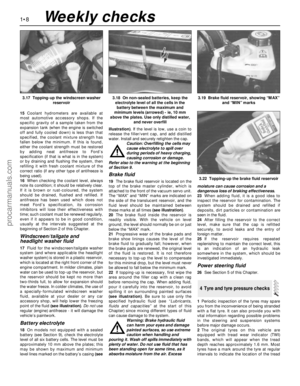 22
22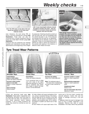 23
23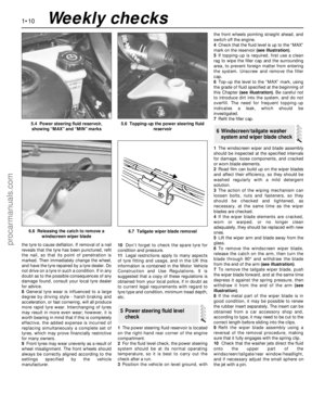 24
24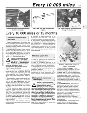 25
25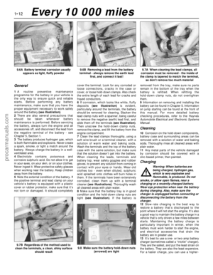 26
26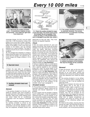 27
27 28
28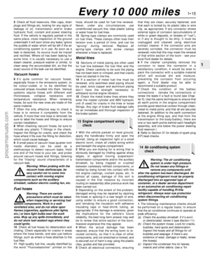 29
29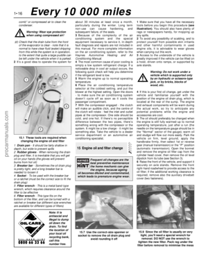 30
30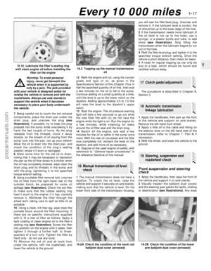 31
31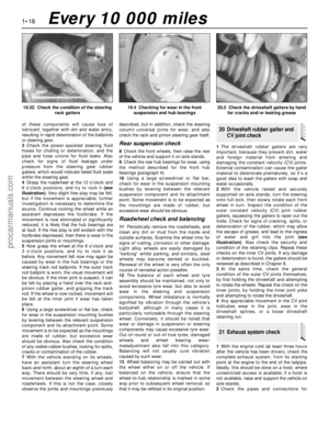 32
32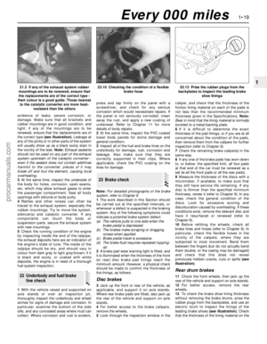 33
33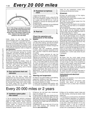 34
34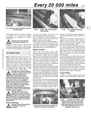 35
35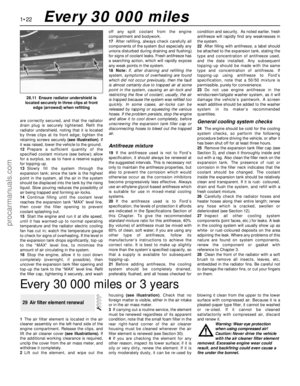 36
36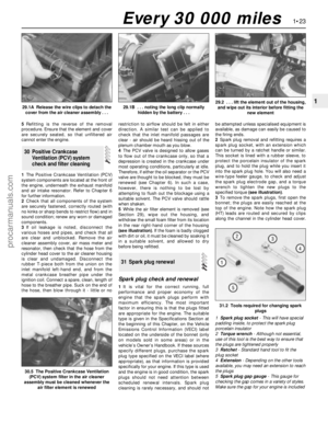 37
37 38
38 39
39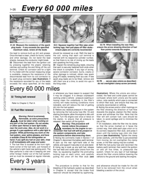 40
40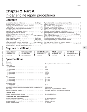 41
41 42
42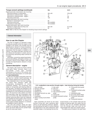 43
43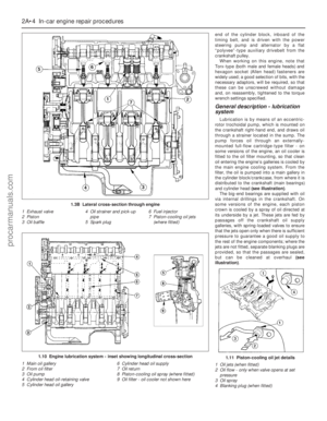 44
44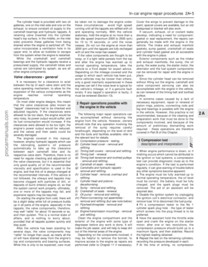 45
45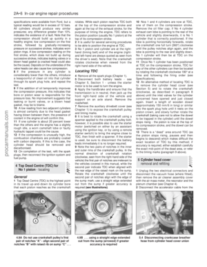 46
46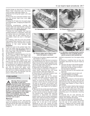 47
47 48
48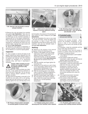 49
49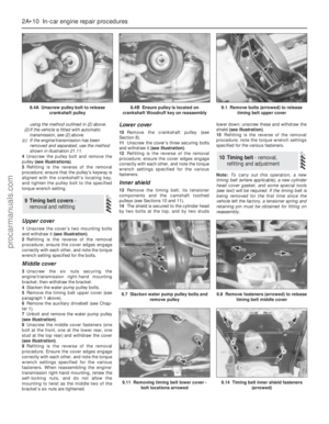 50
50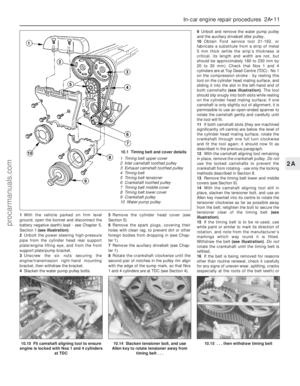 51
51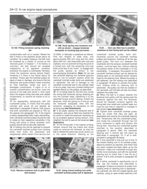 52
52 53
53 54
54 55
55 56
56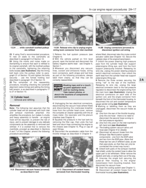 57
57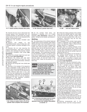 58
58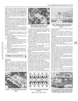 59
59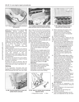 60
60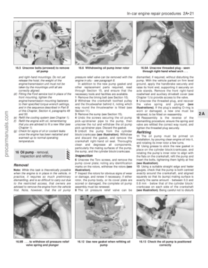 61
61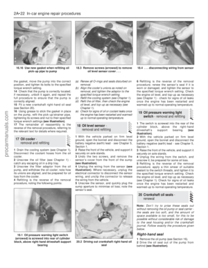 62
62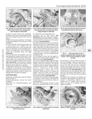 63
63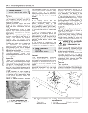 64
64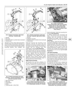 65
65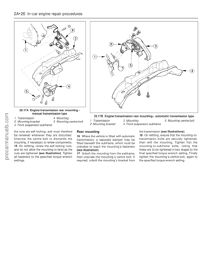 66
66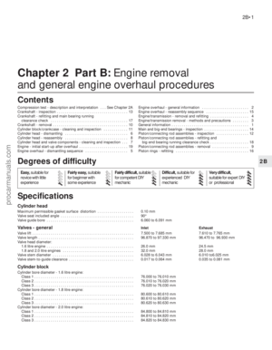 67
67 68
68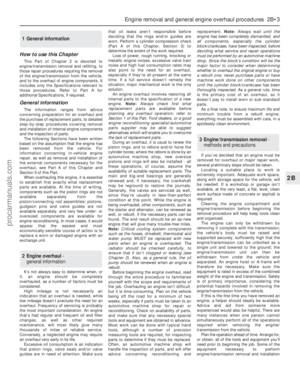 69
69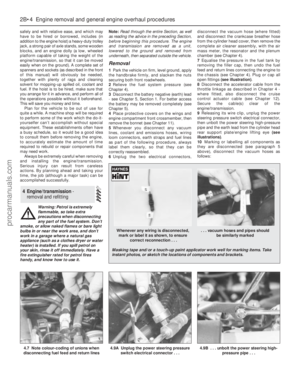 70
70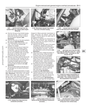 71
71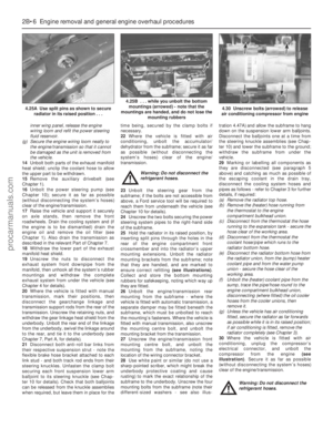 72
72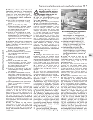 73
73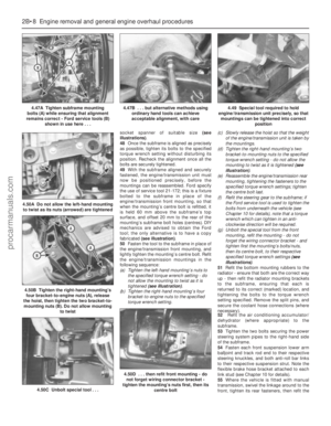 74
74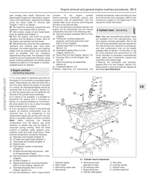 75
75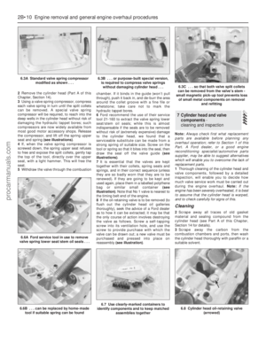 76
76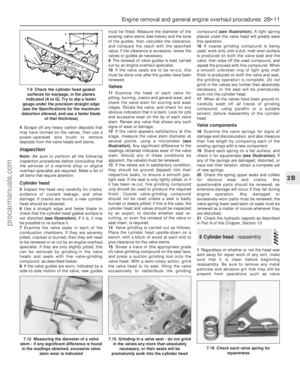 77
77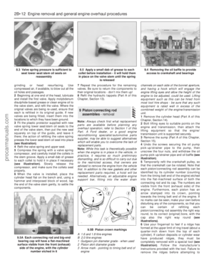 78
78 79
79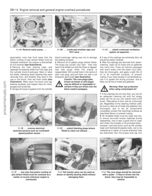 80
80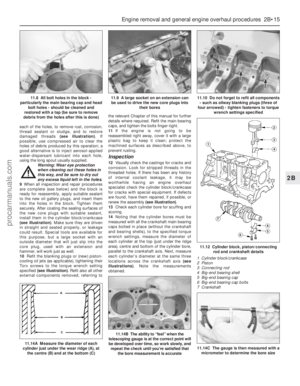 81
81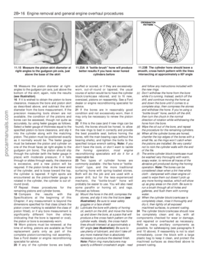 82
82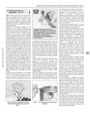 83
83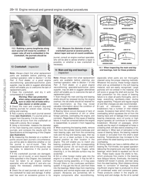 84
84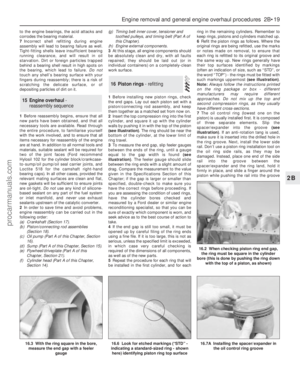 85
85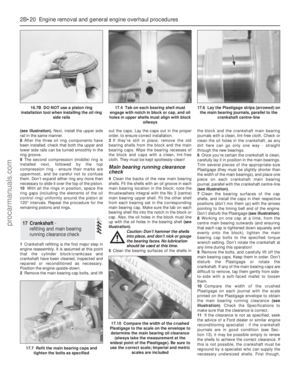 86
86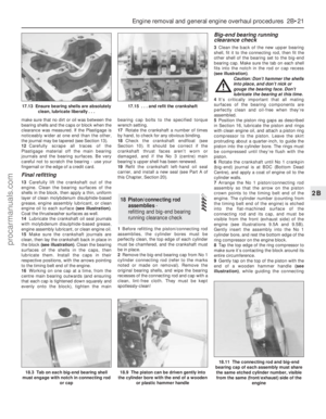 87
87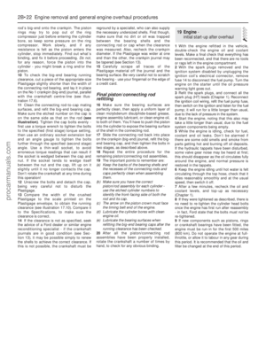 88
88 89
89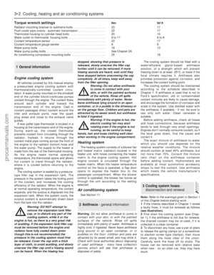 90
90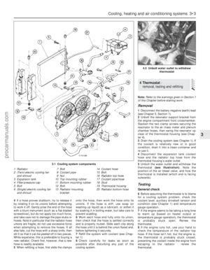 91
91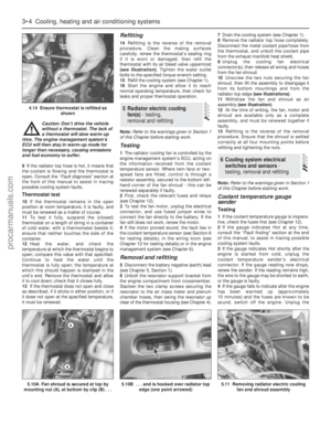 92
92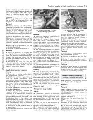 93
93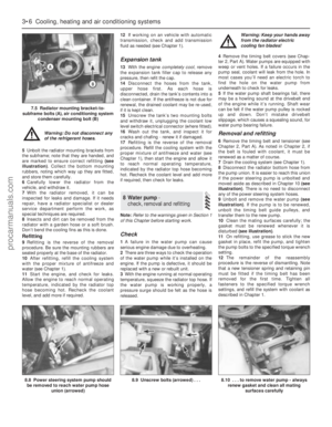 94
94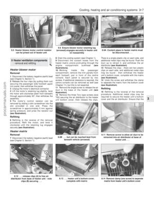 95
95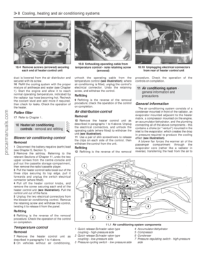 96
96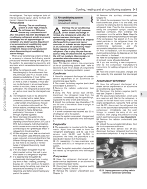 97
97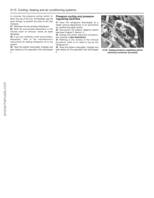 98
98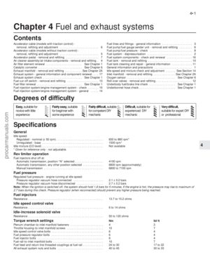 99
99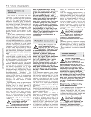 100
100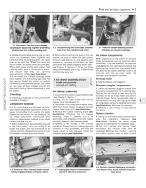 101
101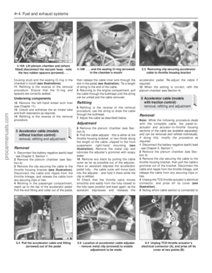 102
102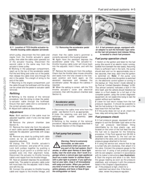 103
103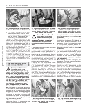 104
104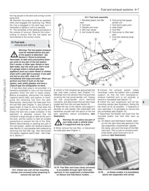 105
105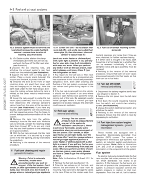 106
106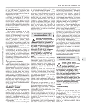 107
107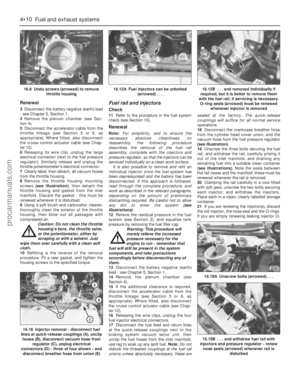 108
108 109
109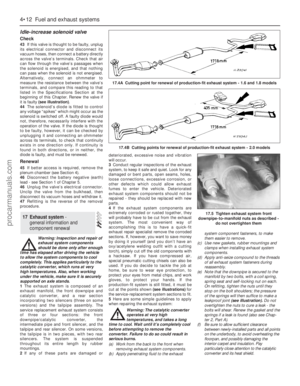 110
110 111
111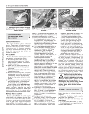 112
112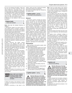 113
113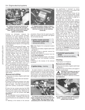 114
114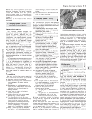 115
115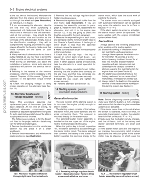 116
116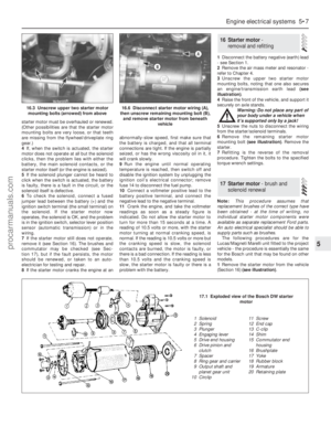 117
117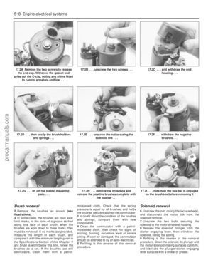 118
118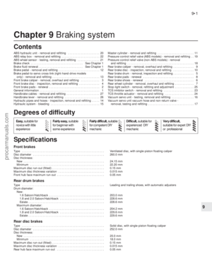 119
119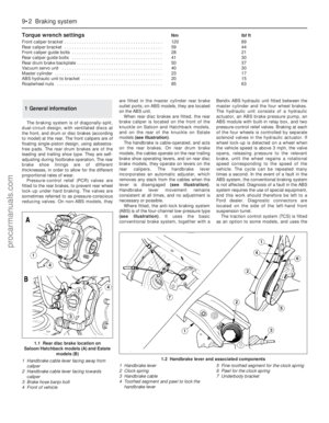 120
120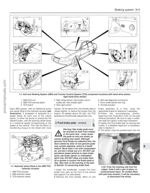 121
121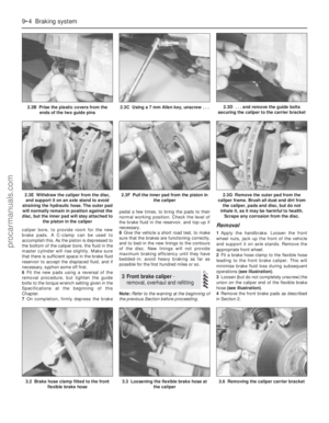 122
122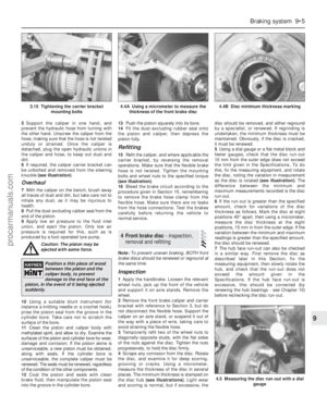 123
123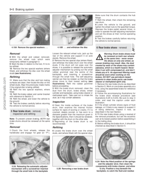 124
124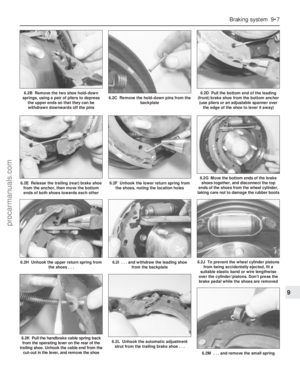 125
125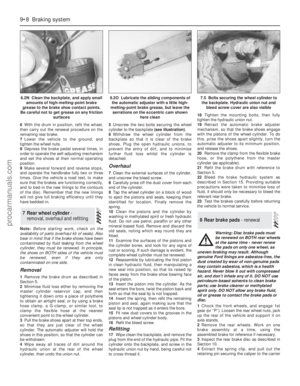 126
126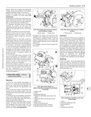 127
127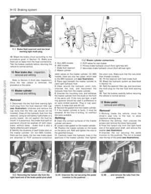 128
128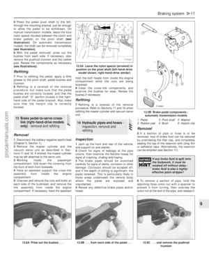 129
129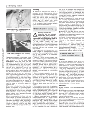 130
130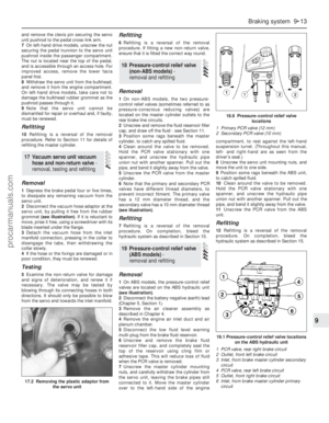 131
131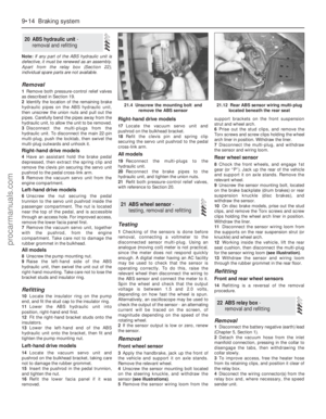 132
132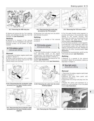 133
133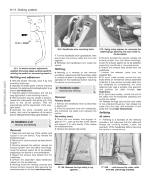 134
134 135
135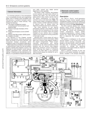 136
136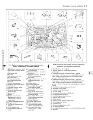 137
137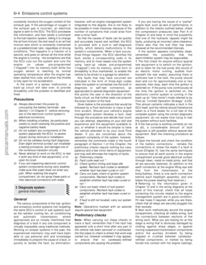 138
138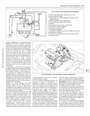 139
139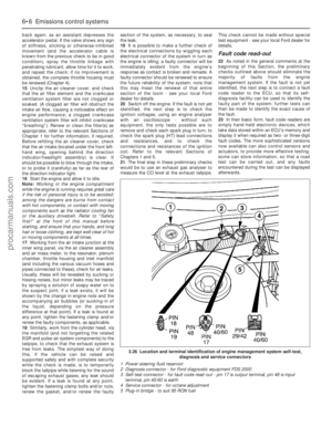 140
140 141
141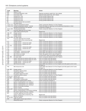 142
142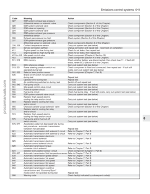 143
143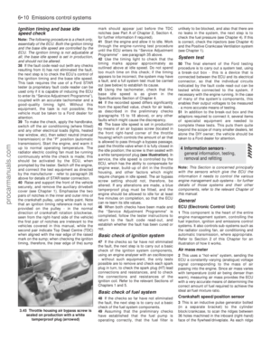 144
144 145
145 146
146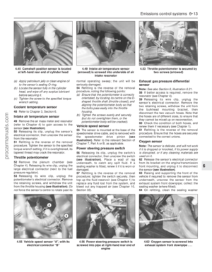 147
147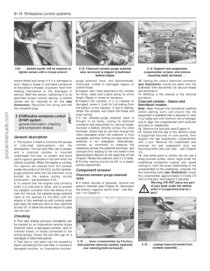 148
148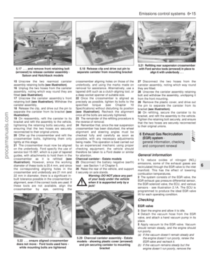 149
149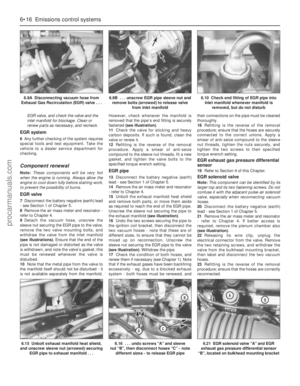 150
150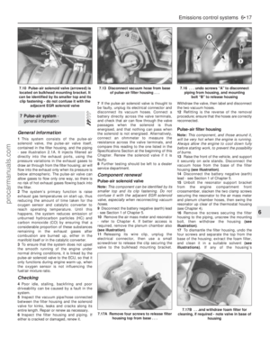 151
151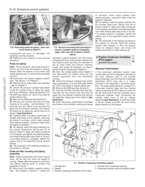 152
152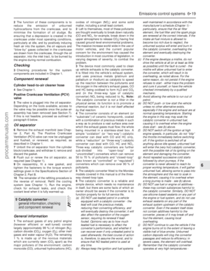 153
153 154
154 155
155 156
156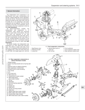 157
157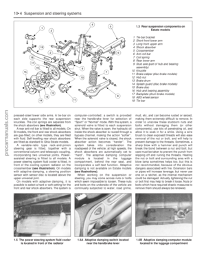 158
158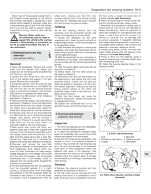 159
159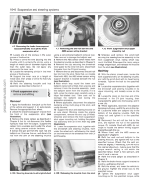 160
160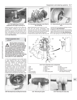 161
161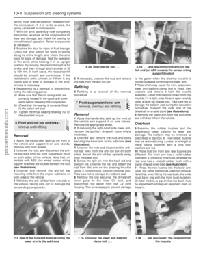 162
162 163
163 164
164 165
165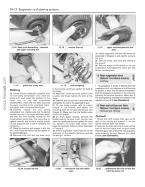 166
166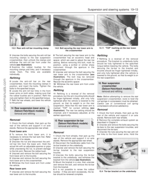 167
167 168
168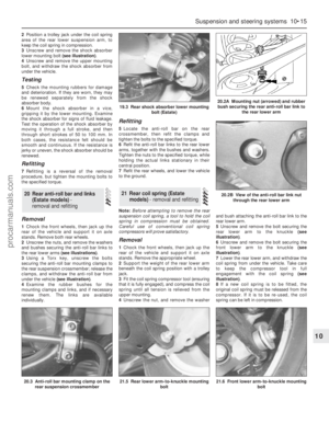 169
169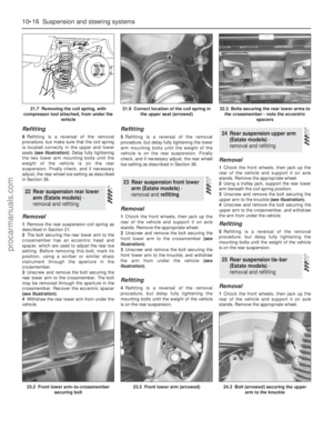 170
170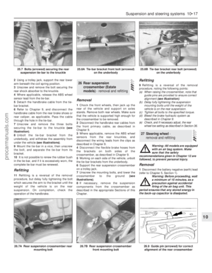 171
171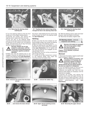 172
172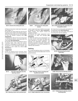 173
173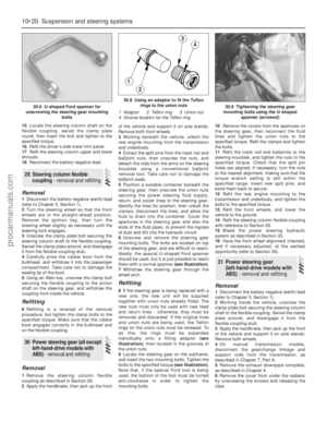 174
174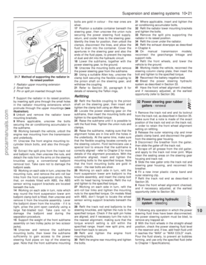 175
175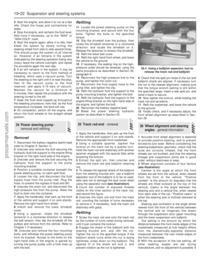 176
176 177
177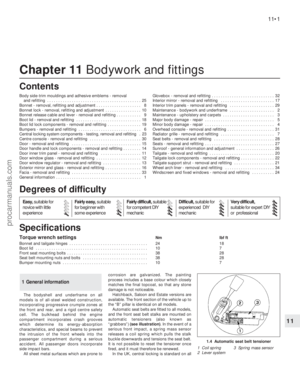 178
178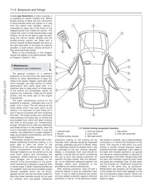 179
179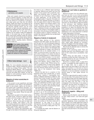 180
180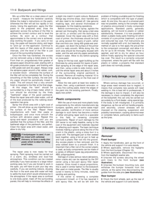 181
181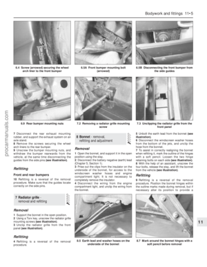 182
182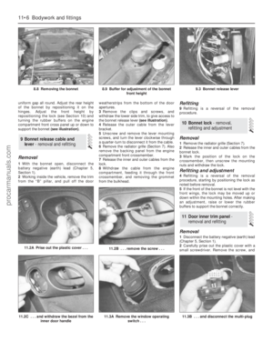 183
183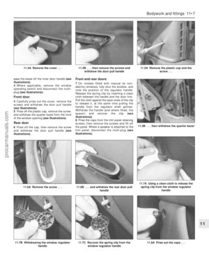 184
184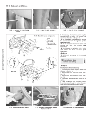 185
185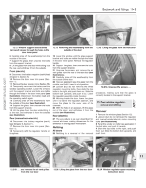 186
186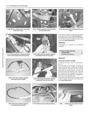 187
187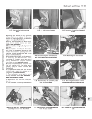 188
188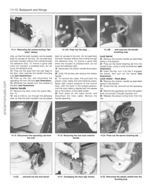 189
189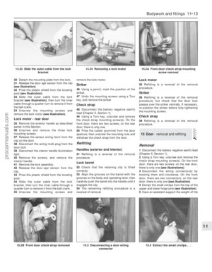 190
190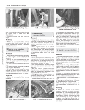 191
191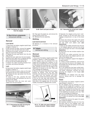 192
192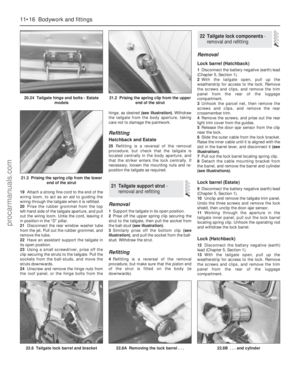 193
193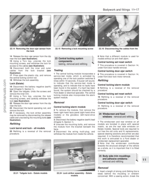 194
194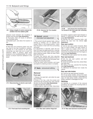 195
195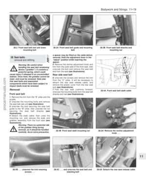 196
196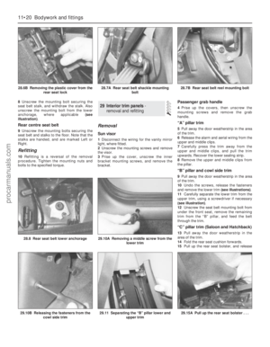 197
197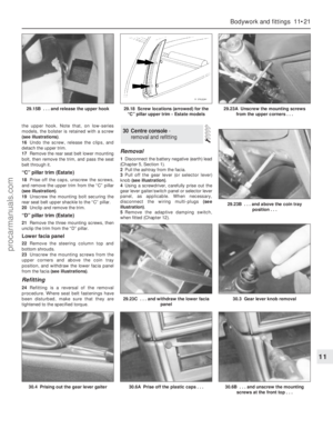 198
198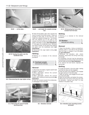 199
199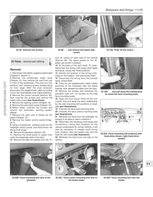 200
200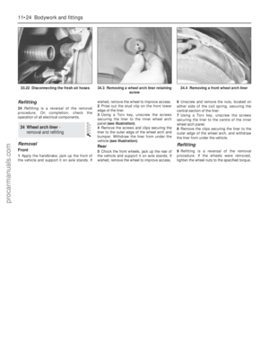 201
201 202
202 203
203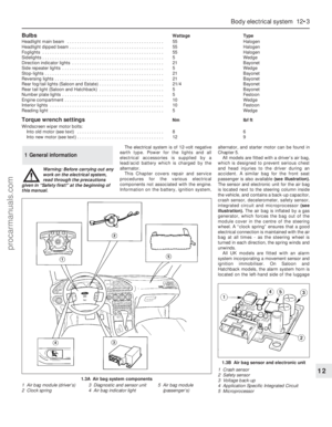 204
204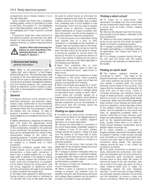 205
205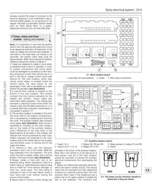 206
206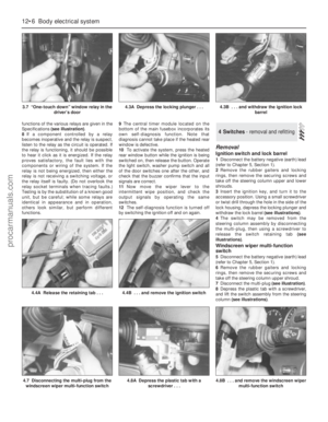 207
207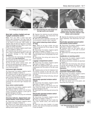 208
208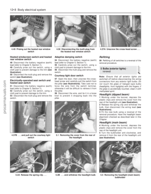 209
209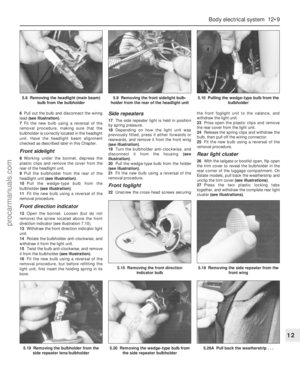 210
210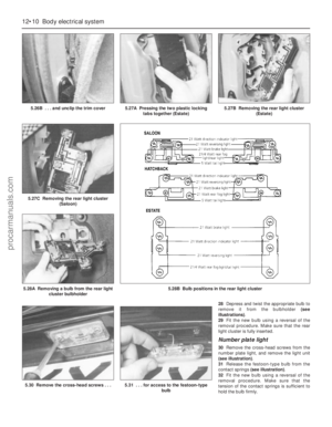 211
211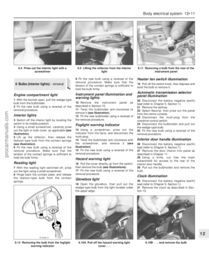 212
212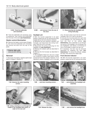 213
213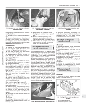 214
214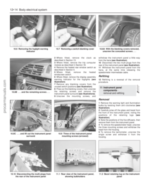 215
215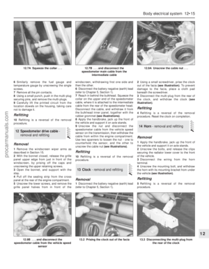 216
216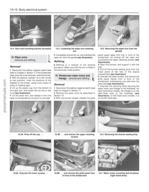 217
217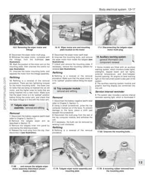 218
218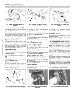 219
219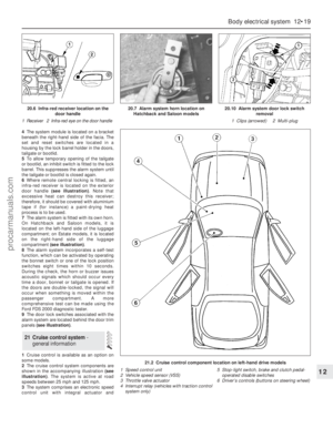 220
220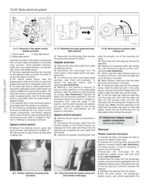 221
221 222
222 223
223 224
224 225
225 226
226 227
227 228
228 229
229 230
230 231
231 232
232 233
233 234
234 235
235 236
236 237
237 238
238 239
239 240
240 241
241 242
242 243
243 244
244 245
245 246
246 247
247 248
248 249
249 250
250 251
251 252
252 253
253 254
254 255
255 256
256 257
257 258
258 259
259 260
260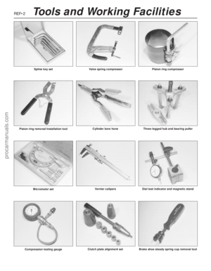 261
261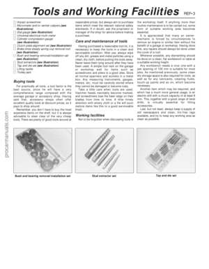 262
262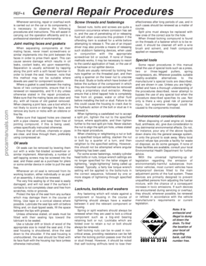 263
263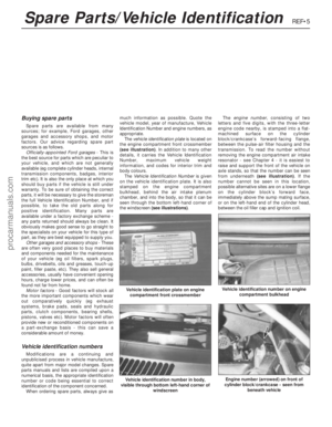 264
264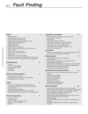 265
265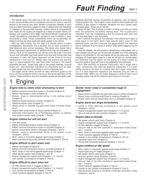 266
266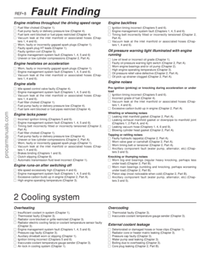 267
267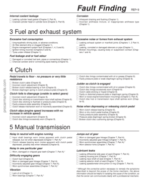 268
268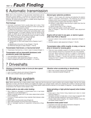 269
269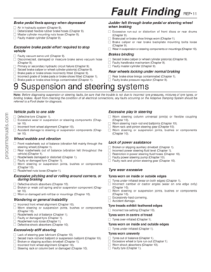 270
270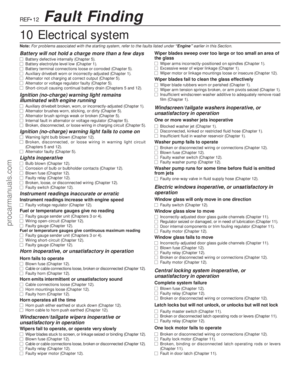 271
271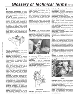 272
272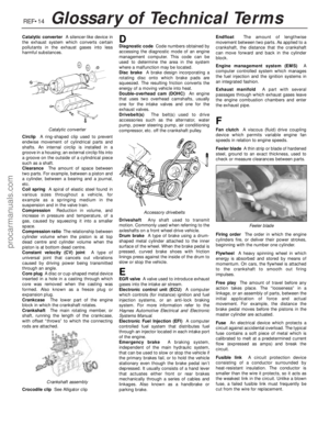 273
273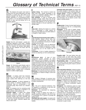 274
274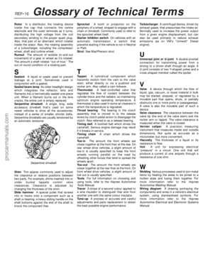 275
275 276
276 277
277 278
278