Page 209 of 279

lead (refer to Chapter 5, Section 1).
49Carefully prise out the switch, using a
cloth pad to prevent da")
Heated windscreen switch and heated
rear window switch
48Disconnect the battery negative (earth)
lead (refer to Chapter 5, Section 1).
49Carefully prise out the switch, using a
cloth pad to prevent damage to the trim (see
illustration).
50Disconnect the multi-plug and remove the
switch (see illustration).
Electrically-operated seat switch and
heated seat switch
51Disconnect the battery negative (earth)
lead (refer to Chapter 5, Section 1).
52Carefully prise out the switch, using a
cloth pad to prevent damage to the trim.
53Disconnect the multi-plug and remove the
switch.
Adaptive damping switch
54Disconnect the battery negative (earth)
lead (refer to Chapter 5, Section 1).
55Carefully prise out the switch, using a
cloth pad to prevent damage to the trim.
56Disconnect the multi-plug and remove the
switch.
Courtesy light door switch
57Open the door, then unscrew the cross-
head screw and carefully pull the switch from
the pillar (see illustrations). Take care not to
force the wire from the switch terminal,
otherwise it will be difficult to retrieve it from
the pillar.
58Disconnect the wire, and tie it in a loose
knot to prevent it dropping back into the
pillar.
Refitting
59Refitting of all switches is a reversal of the
removal procedure.
Note:Ensure that all exterior lights are
switched off before disconnecting the wiring
connectors from any exterior light bulbs. Do
not touch the glass of halogen-type bulbs
(headlights, front foglights) with the fingers; if
the glass is accidentally touched, clean it with
methylated spirit.
Headlight (dipped beam)
1Working under the bonnet, depress the
plastic clips and remove the cover from the
rear of the headlight unit (see illustration).
2Release the spring clip and withdraw the
bulb, then disconnect the wiring lead (see
illustrations).
3Fit the new bulb using a reversal of the
removal procedure. Have the headlight beam
alignment checked as described later in this
Chapter.
Headlight (main beam)
4Working under the bonnet, depress the
plastic clips and remove the cover from the
rear of the headlight unit.
5Turn the bulbholder anti-clockwise, and
remove it from the rear of the headlight unit
(see illustration).
5 Bulbs (exterior lights) -
renewal
12•8 Body electrical system
4.49 Prising out the heated rear window
switch4.50 Disconnecting the multi-plug from
the heated rear window switch4.57A Unscrew the cross-head screw . . .
5.2A Release the spring clip . . .5.2B . . . and withdraw the headlight bulb
4.57B . . . and pull out the courtesy light
switch5.1 Removing the cover from the rear of
the headlight
5.5 Removing the headlight (main beam)
bulbholder
procarmanuals.com
Page 210 of 279
.
7Fit the new bulb using a reversal of the
removal procedure, making sure that the
bulbholder is correctly located in the headlight")
6Pull out the bulb and disconnect the wiring
lead (see illustration).
7Fit the new bulb using a reversal of the
removal procedure, making sure that the
bulbholder is correctly located in the headlight
unit. Have the headlight beam alignment
checked as described later in this Chapter.
Front sidelight
8Working under the bonnet, depress the
plastic clips and remove the cover from the
rear of the headlight unit.
9Pull the bulbholder from the rear of the
headlight unit (see illustration).
10Pull the wedge-type bulb from the
bulbholder (see illustration).
11Fit the new bulb using a reversal of the
removal procedure.
Front direction indicator
12Open the bonnet. Loosen (but do not
remove) the screw located above the front
direction indicator (see illustration 7.10).
13Withdraw the front direction indicator light
unit.
14Rotate the bulbholder anti-clockwise, and
withdraw it from the light unit.
15Twist the bulb anti-clockwise, and remove
it from the bulbholder (see illustration).
16Fit the new bulb using a reversal of the
removal procedure, but before refitting the
light unit, first insert the holding spring in its
bore.
Side repeaters
17The side repeater light is held in position
by spring pressure.
18Depending on how the light unit was
previously fitted, press it either forwards or
rearwards, and remove it from the front wing
(see illustration).
19Turn the bulbholder anti-clockwise, and
disconnect it from the housing (see
illustration).
20Pull the wedge-type bulb from the holder
(see illustration).
21Fit the new bulb using a reversal of the
removal procedure.
Front foglight
22Unscrew the cross-head screws securingthe front foglight unit to the valance, and
withdraw the light unit.
23Prise open the plastic clips and remove
the rear cover from the light unit.
24Release the spring clips and withdraw the
bulb, then pull off the wiring connector.
25Fit the new bulb using a reversal of the
removal procedure.
Rear light cluster
26With the tailgate or bootlid open, flip open
the trim cover to reveal the bulbholder in the
rear corner of the luggage compartment. On
Estate models, pull back the weatherstrip and
unclip the trim cover (see illustrations).
27Press the two plastic locking tabs
together, and withdraw the complete rear light
cluster (see illustrations).
Body electrical system 12•9
12
5.19 Removing the bulbholder from the
side repeater lens/bulbholder5.20 Removing the wedge-type bulb from
the side repeater bulbholder5.26A Pull back the weatherstrip . . .
5.15 Removing the front direction
indicator bulb5.18 Removing the side repeater from the
front wing
5.6 Removing the headlight (main beam)
bulb from the bulbholder5.9 Removing the front sidelight bulb-
holder from the rear of the headlight unit5.10 Pulling the wedge-type bulb from the
bulbholder
procarmanuals.com
Page 211 of 279
.
29Fit the new bulb using a reversal of the
removal procedure. Make sure that the rear
light cluster is fu")
28Depress and twist the appropriate bulb to
remove it from the bulbholder (see
illustrations).
29Fit the new bulb using a reversal of the
removal procedure. Make sure that the rear
light cluster is fully inserted.
Number plate light
30Remove the cross-head screws from the
number plate light, and remove the light unit
(see illustration).
31Release the festoon-type bulb from the
contact springs (see illustration).
32Fit the new bulb using a reversal of the
removal procedure. Make sure that the
tension of the contact springs is sufficient to
hold the bulb firmly.
12•10 Body electrical system
5.26B . . . and unclip the trim cover5.27A Pressing the two plastic locking
tabs together (Estate)
5.30 Remove the cross-head screws . . .5.31 . . . for access to the festoon-type
bulb
5.27B Removing the rear light cluster
(Estate)
5.28A Removing a bulb from the rear light
cluster bulbholder
5.27C Removing the rear light cluster
(Saloon)
5.28B Bulb positions in the rear light cluster
procarmanuals.com
Page 212 of 279

Engine compartment light
1With the bonnet open, pull the wedge-type
bulb from the bulbholder.
2Fit the new bulb using a reversal of the
removal procedure.
Interior lights
3Switch off the interior light by locating the
switch in its middle position.
4Using a small screwdriver, carefully prise
out the light or bulb cover, as applicable (see
illustration).
5Lift up the reflector, then release the
festoon-type bulb from the contact springs
(see illustration).
6Fit the new bulb using a reversal of the
removal procedure. Make sure that the
tension of the contact springs is sufficient to
hold the bulb firmly.
Reading light
7With the reading light switched off, prise
out the light using a small screwdriver.
8Hinge back the contact plate, and release
the festoon-type bulb from the contact
springs.9Fit the new bulb using a reversal of the
removal procedure. Make sure that the
tension of the contact springs is sufficient to
hold the bulb firmly.
Instrument panel illumination and
warning lights
10Remove the instrument panel as
described in Section 10.
11Twist the bulbholder anti-clockwise to
remove it (see illustration).
12Fit the new bulbholder using a reversal of
the removal procedure.
Foglight warning indicator
13Using a screwdriver, prise out the
indicator from the facia, and disconnect the
multi-plug.
14Twist the bulbholder anti-clockwise with
the screwdriver, and remove it (see
illustration).
15Fit the new bulb using a reversal of the
removal procedure.
Hazard warning light
16Pull the cover directly up from the switch,
then remove the bulb (see illustrations).
17Fit the new bulb using a reversal of the
removal procedure.
Glovebox light
18Open the glovebox, then pull out the
wedge-type bulb from the light located under
the upper edge.
Heater fan switch illumination
19Pull off the switch knob, then depress and
twist the bulb to remove it.
Automatic transmission selector
panel illumination
20Disconnect the battery negative (earth)
lead (refer to Chapter 5, Section 1).
21Remove the ashtray.
22Select Neutral, then prise out the panel
from the centre console.
23Disconnect the multi-plug from the
overdrive control switch.
24Disconnect the bulbholder and pull out
the wedge-type bulb.
25Fit the new bulb using a reversal of the
removal procedure.
Interior door handle illumination
26Disconnect the battery negative (earth)
lead (refer to Chapter 5, Section 1).
27Remove the door interior trim panel as
described in Chapter 11.
28Using a knife, cut free the foam
watershield for access to the rear of the
interior door handle.
29Pull out the bulbholder and remove the
bulb.
Clock illumination
30Disconnect the battery negative (earth)
lead (refer to Chapter 5, Section 1).
31Remove the clock as described in Sec-
tion 13.
6 Bulbs (interior lights) - renewal
Body electrical system 12•11
12
6.14 Removing the bulb from the foglight
warning indicator6.16A Pull off the hazard warning light
cover . . .6.16B . . . and remove the bulb
6.4 Prise out the interior light with a
screwdriver6.5 Lifting the reflector from the interior
light6.11 Removing a bulb from the rear of the
instrument panel
procarmanuals.com
Page 213 of 279
.
Heater control illumination
33Remove the heater control panel (Cha")
32Twist the bulbholder anti-clockwise using
a screwdriver, then remove the bulbholder
from the rear of the clock (see illustrations).
Heater control illumination
33Remove the heater control panel (Chapter
3), then twist the bulbholder anti-clockwise
and remove the bulb from the rear of the
panel.
Removal
1Disconnect the battery negative (earth) lead
(refer to Chapter 5, Section 1).
Headlight unit
2With the bonnet supported in its open
position, loosen (but do not remove) the screw
located above the front direction indicator.
3Withdraw the front direction indicator unit
forwards, and disconnect the wiring multi-
plug. Place the unit to one side.
4Disconnect the wiring multi-plug for the
headlight unit (see illustration).
5Remove the radiator grille as described in
Chapter 11.
6Remove the front bumper as described in
Chapter 11.
7The headlights fitted from new are a single
unit, joined by a plastic back-piece running
across the front of the vehicle. However, if it is
required to renew a headlight unit on one sideonly, the back-piece must first be removed
complete, then cut in half on the bench.
8Unscrew the mounting bolts from each side
of the headlight unit, and withdraw the unit
from the front of the vehicle (see
illustrations). Use a hacksaw to cut through
the centre of the headlight unit (ie between the
two headlights), and obtain a connecting kit
from a Ford dealer to attach the new unit.
9If necessary, the lens may be removed
separately by releasing the clips (see
illustrations). To remove the diffuser, release
the clips, then remove the rubber seal.
Front direction indicator
10With the bonnet supported in its open
position, loosen (but do not remove) the screw
7 Exterior light units -
removal and refitting
12•12 Body electrical system
6.32A Twist the bulbholder
anti-clockwise . . .6.32B . . . and remove it from the rear of
the clock7.4 Disconnecting the headlight unit
wiring multi-plug
7.8D Using a hacksaw to cut through the
middle of the headlight back-piece, in
order to fit a new unit7.9A Release the clips . . .7.9B . . . and remove the headlight lens
7.8A Unscrew the outer mounting
screws . . .7.8B . . . and inner mounting screws . . .7.8C . . . and withdraw the headlight unit
assembly
procarmanuals.com
Page 214 of 279
.
11Withdraw the front direction indicator light
unit.
12Rotate the bulbholder anti-clockwise, and
withdraw it from the light unit. Altern")
located above the front direction indicator
(see illustration).
11Withdraw the front direction indicator light
unit.
12Rotate the bulbholder anti-clockwise, and
withdraw it from the light unit. Alternatively,
the wiring plug can be disconnected from the
bulbholder, leaving the bulb in position (see
illustration). Remove the light unit.
Foglight (front)
13Unscrew the cross-head screws securing
the front foglight unit to the valance, and
withdraw the light unit from the valance.
14Prise open the plastic clips, and remove
the rear cover from the light unit.
15Release the spring clips and withdraw the
bulb, then pull off the wiring connector.
Remove the foglight unit.
Rear light cluster
16With the tailgate or bootlid open, unhook
the parcel net (where fitted) from the rear of
the luggage compartment.
17On Saloon and Hatchback models,
remove the screws, release the clips, and
remove the trim panel from the rear cross
panel. On Estate models, it is sufficient to
open the flap.
18Remove the screws, and press the rear
light trim cover from the guides (where
applicable).
19Disconnect the wiring multi-plug.
20Unscrew the four mounting nuts, and
withdraw the light unit from the outside of the
vehicle (see illustrations).
Rear number plate light assembly
21Remove both number plate lights as
described in Section 5.
22With the tailgate or bootlid open, remove
the screws and withdraw the inner trim panel.
23Unscrew the nuts, and remove the outer
cover and number plate base from the
tailgate.
24Disconnect the multi-plug and remove the
light assembly.
Refitting
25Refitting of all the external light units is a
reversal of the removal procedure, noting the
following points:(a) When refitting the rubber seal on the
headlight unit, note that it has a tapered
seat.
(b) If one or both headlights have been
disturbed, have the beam alignment
checked as described in the next Section.
(c) When refitting the rear light cluster, check
the condition of the sealer on the body
panel, and if necessary renew it.
1Accurate adjustment of the headlight beam
is only possible using optical beam-setting
equipment. This work should therefore be
carried out by a Ford dealer, or other service
station with the necessary facilities.
2Temporary adjustment can be made after
renewal of a headlight bulb or unit, or as an
emergency measure if the alignment is
incorrect following accident damage. Turn the
adjustment screws on the top of the headlamp
unit to make the adjustment (see illustration).
3Before making any adjustments to the
settings, it is important that the tyre pressures
are correct, and that the vehicle is standing on
level ground. Bounce the front of the vehicle a
few times to settle the suspension. Ideally,
somebody of average size should sit in the
driver’s seat during the adjustment, and the
vehicle should have a full tank of fuel. Where a
vehicle is fitted with an electrical beam
levelling system, set the switch to the “O”
position before making any adjustments.4Whenever temporary adjustments are
made, the settings must be checked and if
necessary reset by a Ford dealer or other
qualified person as soon as possible.
Removal
1Remove the headlight unit as described in
Section 7, then remove the cover.
2Disconnect the wiring multi-plug from the
motor.
3Rotate the motor upwards approximately
60°, then pull it forwards slightly.
4Disconnect the adjustment spindle by
pressing the ball coupling to one side, away
from the socket on the reflector.
5Withdraw the motor from the headlight unit.
Refitting
6Refitting is a reversal of the removal
procedure, but make sure that the motor is
turned down until it engages the stop.
Removal
1Disconnect the battery negative (earth) lead
(refer to Chapter 5, Section 1).
10 Instrument panel -
removal and refitting
9 Headlight levelling motor -
removal and refitting
8 Headlight beam alignment-
checking and adjustment
Body electrical system 12•13
12
7.20B Removing the rear light cluster unit
8.2 Headlight beam setting adjustment
screws
1 Vertical alignment screw
2 Horizontal alignment screw
7.10 Loosen the front direction indicator
retaining screw7.12 Disconnecting the wiring plug from
the indicator bulbholder7.20A Rear light cluster mounting nuts
(arrowed)
procarmanuals.com
Page 215 of 279

2Where fitted, remove the clock as
described in Section 13.
3Where fitted, remove the trip computer
module as described in Section 18.
4Remove the heated rear window switch as
described in Section 4.
5Where fitted, remove the heated
windscreen switch.
6Where fitted, remove the display assembly
warning indicator for the foglights (see
illustration).
7Remove any blanking covers from the
unused switch positions (see illustration).
8Prise out the blanking covers, then unscrew
the retaining screws and remove the
instrument panel surround (see illustrations).
9Unscrew the mounting screws, andwithdraw the instrument panel a little way
from the facia (see illustration).
10Disconnect the two multi-plugs from the
rear of the instrument panel (see illustration).
11Withdraw the instrument panel from the
facia, at the same time releasing the
speedometer intermediate cable.
Refitting
12Refitting is a reversal of the removal
procedure.
Removal
1Remove the warning light and illumination
bulbs by twisting them anti-clockwise (see
illustration).
2Carefully prise off the glass and bezel from
the front of the instrument panel, noting the
positions of the retaining lugs (see
illustration).
3Note the positions of the five diffusers, then
remove them from the instrument panel.
4To remove the speedometer head, unscrew
the three mounting screws and withdraw the
head from the housing.
5To remove the tachometer, unscrew the
single screw and withdraw it from the
housing.
11 Instrument panel
components-
removal and refitting
12•14 Body electrical system
10.6 Removing the foglight warning
indicator10.7 Removing a switch blanking cover10.8A With the blanking covers removed,
unscrew the concealed screws . . .
10.10 Disconnecting the multi-plugs from
the rear of the instrument panel11.1 Rear view of the instrument panel,
showing bulbholders11.2 Bezel retaining lug on the instrument
panel
10.8C . . . and lift out the instrument panel
surround10.9 Three of the instrument panel
mounting screws (arrowed)
10.8B . . . and the remaining screws . . .
procarmanuals.com
Page 216 of 279

6Similarly remove the fuel gauge and
temperature gauge by unscrewing the single
screws.
7Remove all the pin contacts.
8Using a small punch, push in the multi-plug
securing pins, and remove the multi-plugs.
9Carefully lift the printed circuit from the
location dowels on the housing, taking care
not to damage it.
Refitting
10Refitting is a reversal of the removal
procedure.
Removal
1Remove the windscreen wiper arms as
described in Section 15.
2With the bonnet closed, release the grille
panel upper edge from just in front of the
windscreen, by prising off the caps and
unscrewing the upper retaining screws.
3Open the bonnet, and support with the
stay.
4Pull off the sealing strip from the cross
panel at the rear of the engine compartment.
5Unscrew the lower screws, and remove the
grille panel halves from in front of thewindscreen, withdrawing first one side and
then the other.
6Disconnect the battery negative (earth) lead
(refer to Chapter 5, Section 1).
7Reach in behind the bulkhead. Squeeze the
collar on the upper end of the speedometer
cable, where it is attached to the intermediate
cable from the rear of the speedometer head.
Disconnect the cable, and withdraw it from
the bulkhead inner panel, together with the
rubber grommet (see illustrations).
8Apply the handbrake, jack up the front of
the vehicle and support it on axle stands.
9Unscrew the nut and disconnect the
speedometer cable from the vehicle speed
sensor on the transmission, then withdraw the
cable from within the engine compartment.
Use two spanners to loosen the nut - one to
counterhold the sensor, and the other to
unscrew the cable nut (see illustrations).Refitting
10Refitting is a reversal of the removal
procedure.
Removal
1Disconnect the battery negative (earth) lead
(refer to Chapter 5, Section 1).2Using a small screwdriver, prise the clock
out of the facia (see illustration). To prevent
damage to the facia, place a cloth pad
beneath the screwdriver.
3Disconnect the multi-plug from the rear of
the clock, and withdraw the clock (see
illustration).
Refitting
4Refitting is a reversal of the removal
procedure. Reset the clock on completion.
Removal
1Apply the handbrake, jack up the front of
the vehicle and support it on axle stands.
2Unscrew the bolts, and release the clips
securing the radiator lower cover to the front
of the vehicle.
3Disconnect the wiring from the horn
terminal.
4Unscrew the mounting bolt, and withdraw
the horn with its mounting bracket from under
the vehicle (see illustration).
Refitting
5Refitting is a reversal of the removal
procedure.
14 Horn - removal and refitting
13 Clock- removal and refitting
12 Speedometer drive cable -
removal and refitting
Body electrical system 12•15
12
12.9B . . . and disconnect the
speedometer cable from the vehicle speed
sensor13.2 Prising the clock out of the facia13.3 Disconnecting the multi-plug from
the rear of the clock
12.7A Squeeze the collar . . .12.7B . . . and disconnect the
speedometer main cable from the
intermediate cable12.9A Unscrew the cable nut . . .
procarmanuals.com
 1
1 2
2 3
3 4
4 5
5 6
6 7
7 8
8 9
9 10
10 11
11 12
12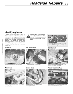 13
13 14
14 15
15 16
16 17
17 18
18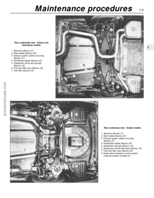 19
19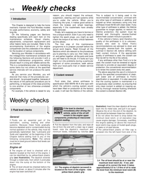 20
20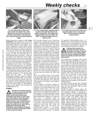 21
21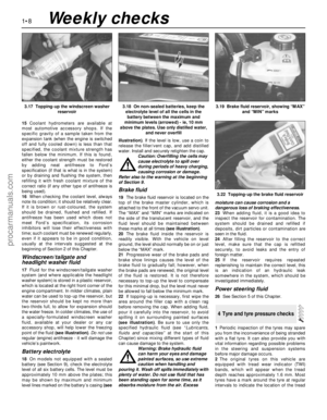 22
22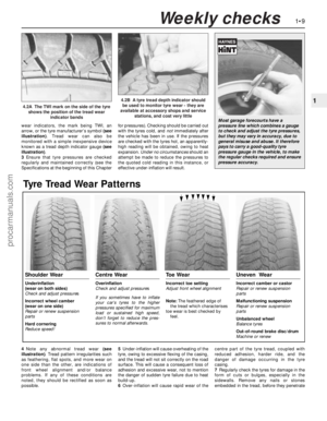 23
23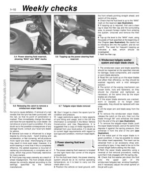 24
24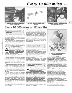 25
25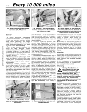 26
26 27
27 28
28 29
29 30
30 31
31 32
32 33
33 34
34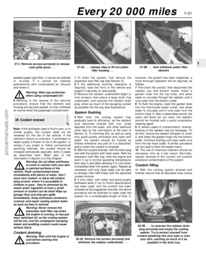 35
35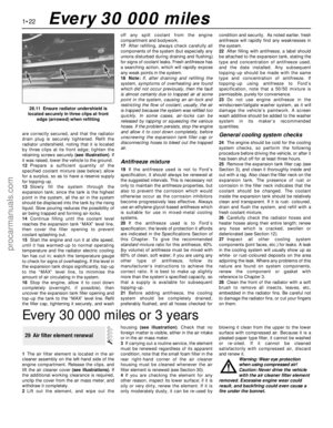 36
36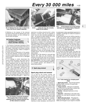 37
37 38
38 39
39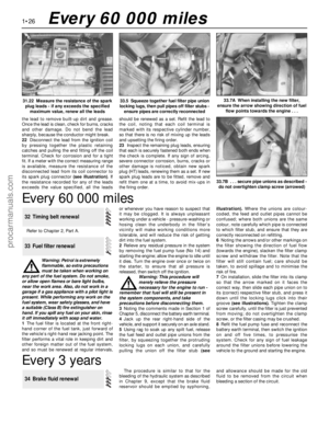 40
40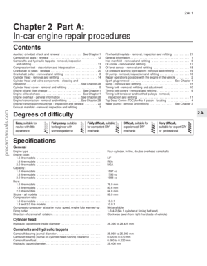 41
41 42
42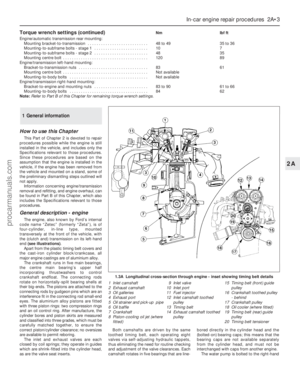 43
43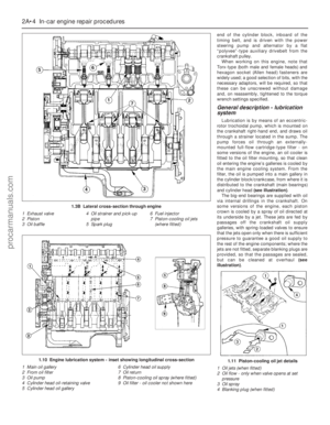 44
44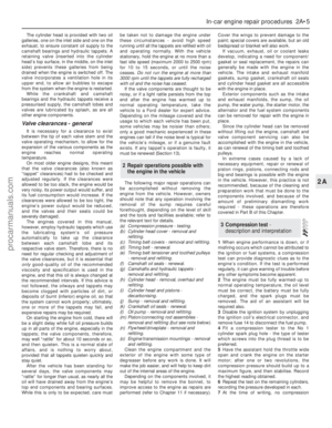 45
45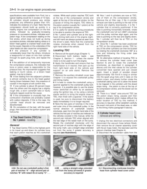 46
46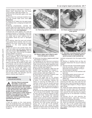 47
47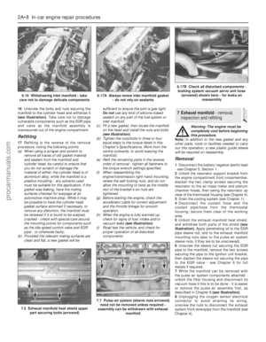 48
48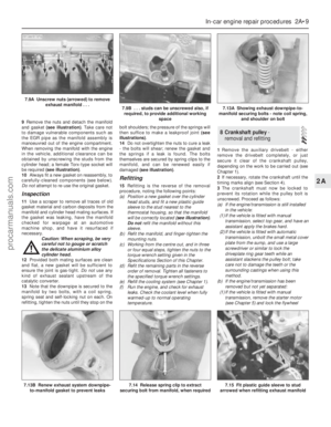 49
49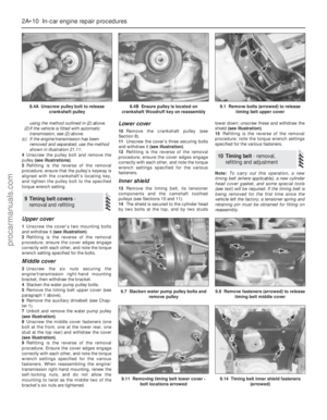 50
50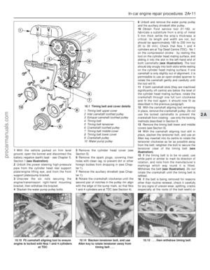 51
51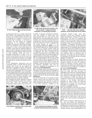 52
52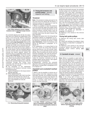 53
53 54
54 55
55 56
56 57
57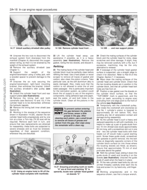 58
58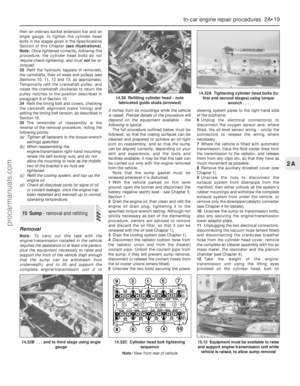 59
59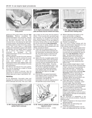 60
60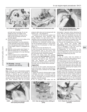 61
61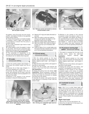 62
62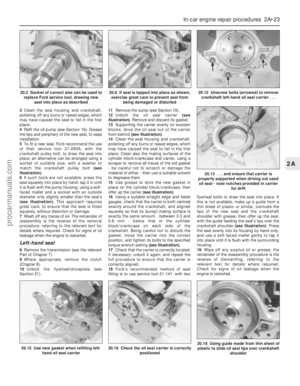 63
63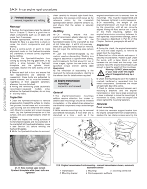 64
64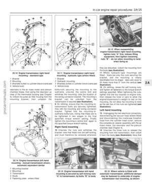 65
65 66
66 67
67 68
68 69
69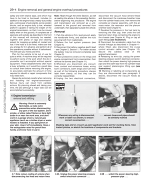 70
70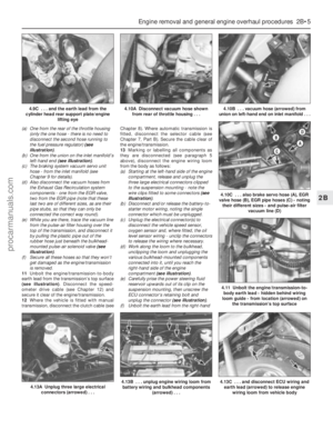 71
71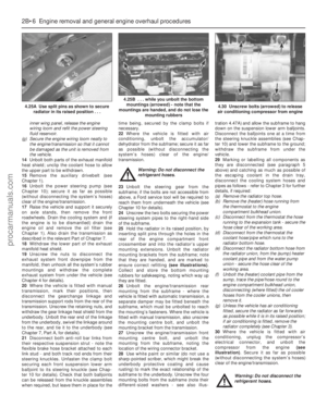 72
72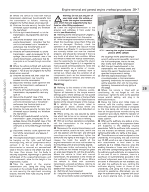 73
73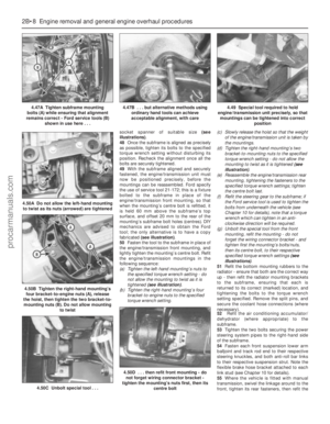 74
74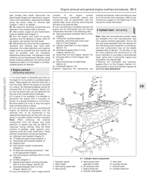 75
75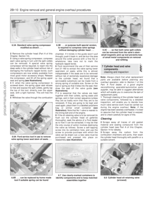 76
76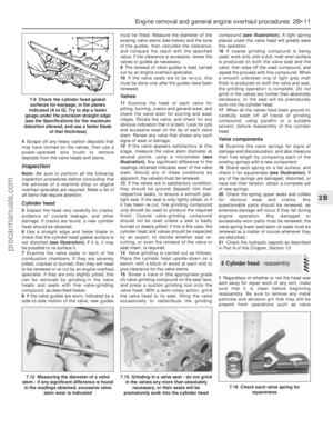 77
77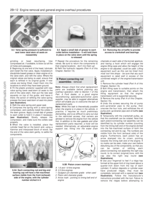 78
78 79
79 80
80 81
81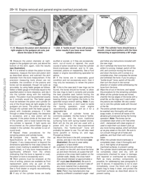 82
82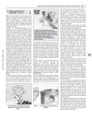 83
83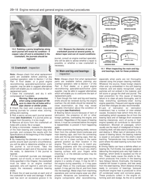 84
84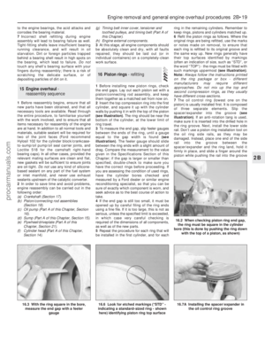 85
85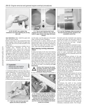 86
86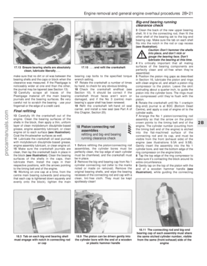 87
87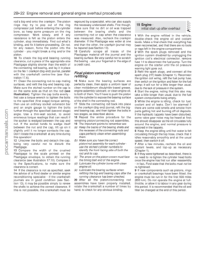 88
88 89
89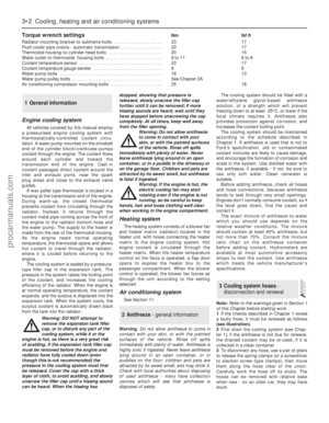 90
90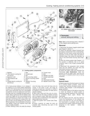 91
91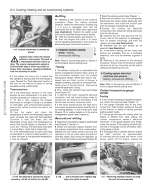 92
92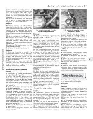 93
93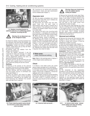 94
94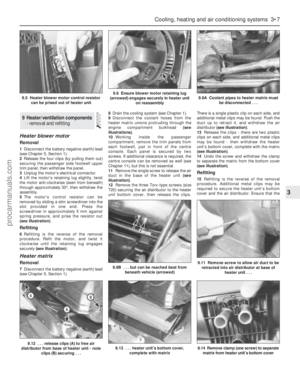 95
95 96
96 97
97 98
98 99
99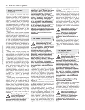 100
100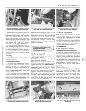 101
101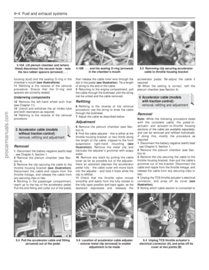 102
102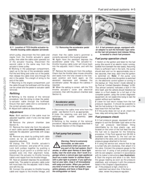 103
103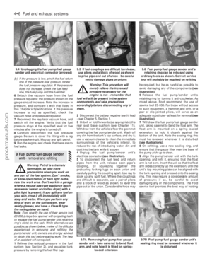 104
104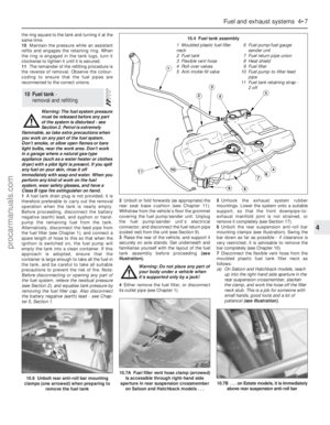 105
105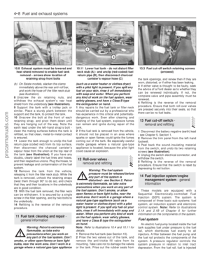 106
106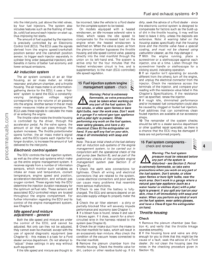 107
107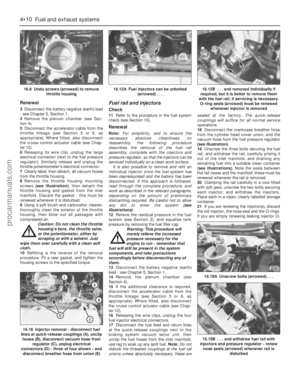 108
108 109
109 110
110 111
111 112
112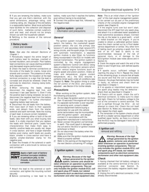 113
113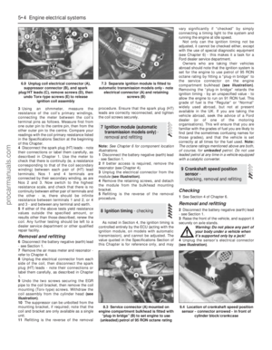 114
114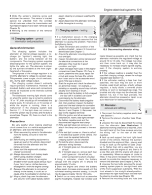 115
115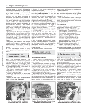 116
116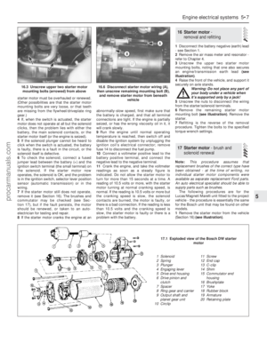 117
117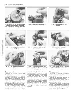 118
118 119
119 120
120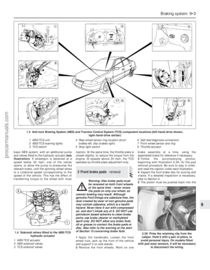 121
121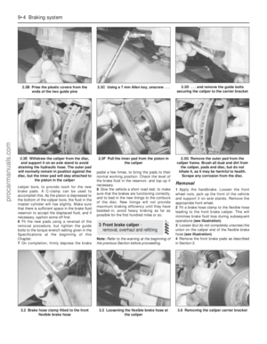 122
122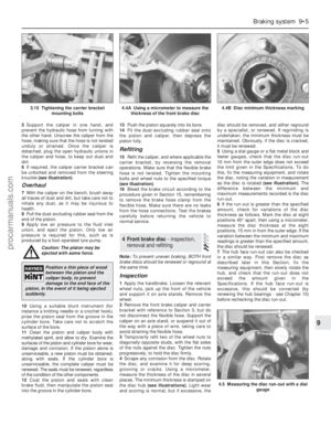 123
123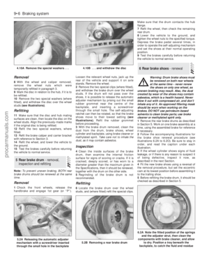 124
124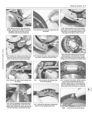 125
125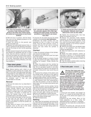 126
126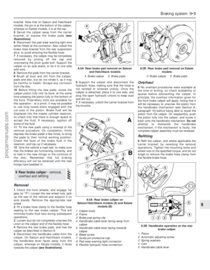 127
127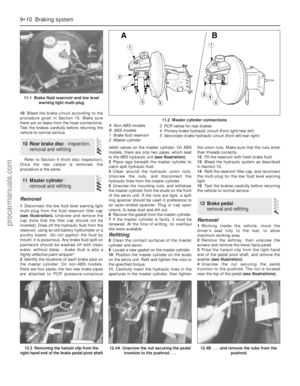 128
128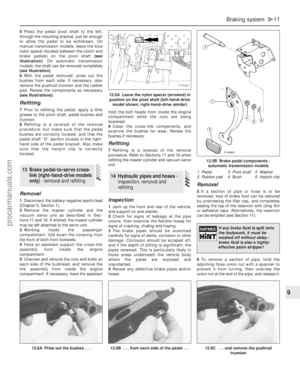 129
129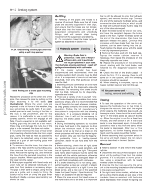 130
130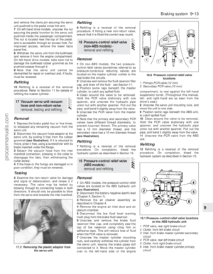 131
131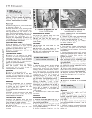 132
132 133
133 134
134 135
135 136
136 137
137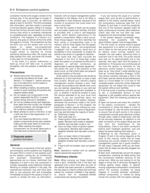 138
138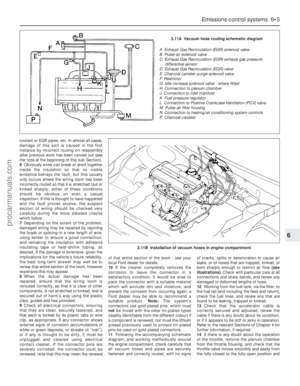 139
139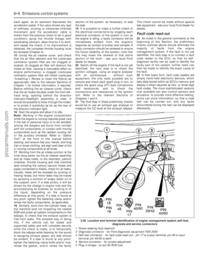 140
140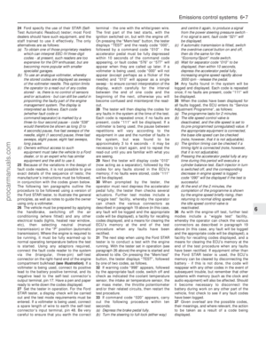 141
141 142
142 143
143 144
144 145
145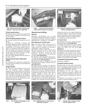 146
146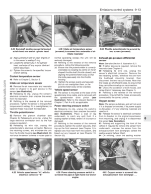 147
147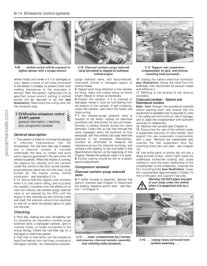 148
148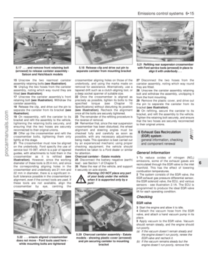 149
149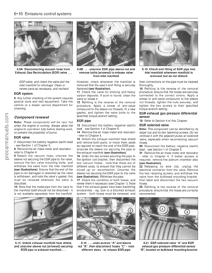 150
150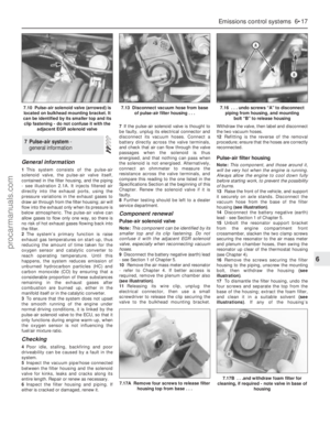 151
151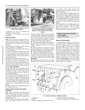 152
152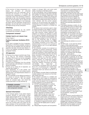 153
153 154
154 155
155 156
156 157
157 158
158 159
159 160
160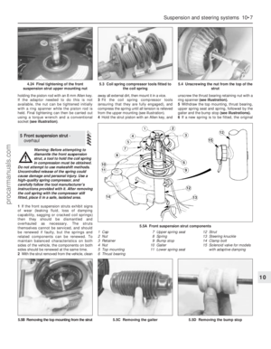 161
161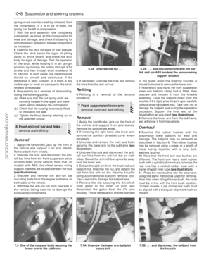 162
162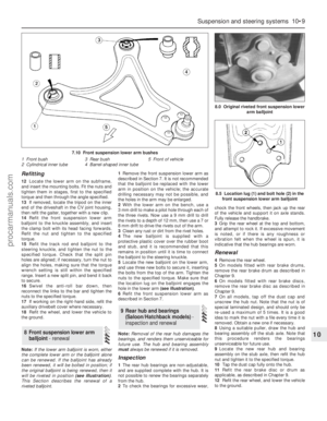 163
163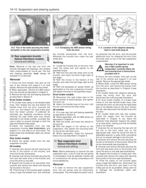 164
164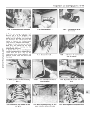 165
165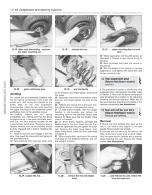 166
166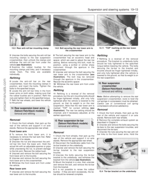 167
167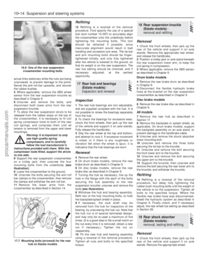 168
168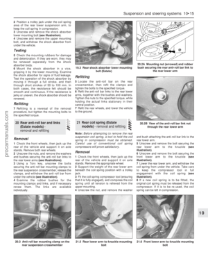 169
169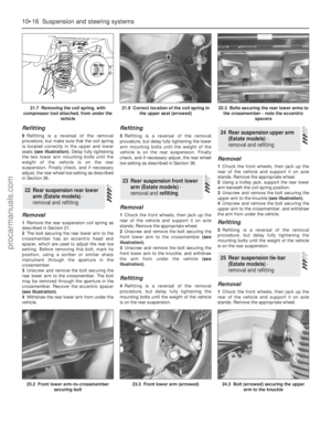 170
170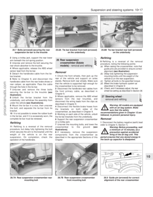 171
171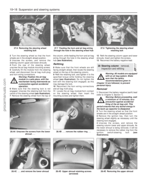 172
172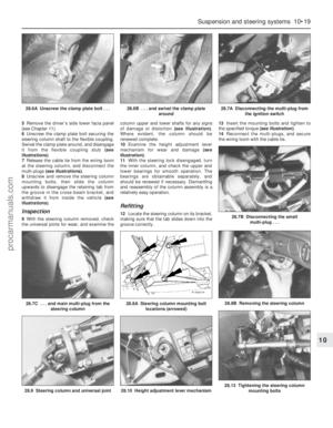 173
173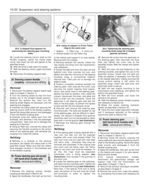 174
174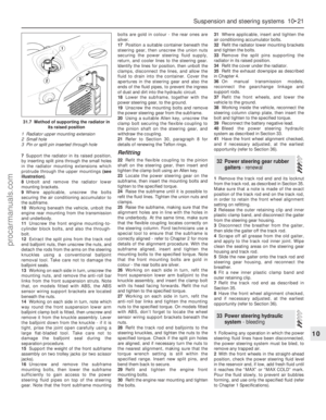 175
175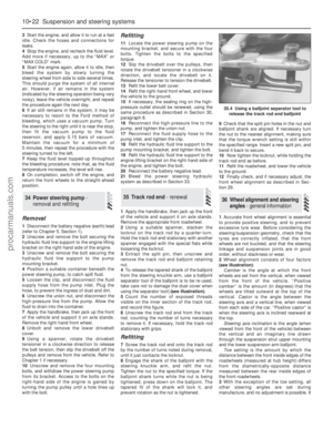 176
176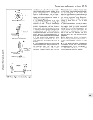 177
177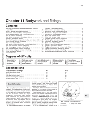 178
178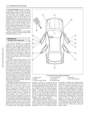 179
179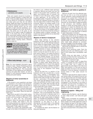 180
180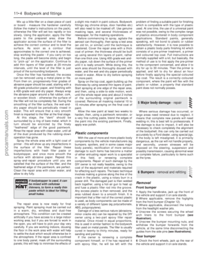 181
181 182
182 183
183 184
184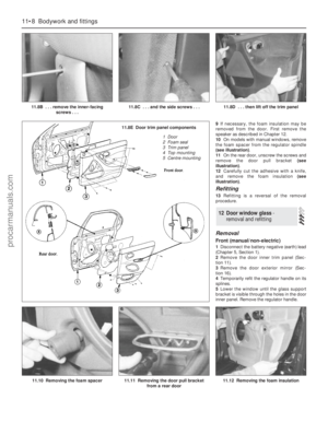 185
185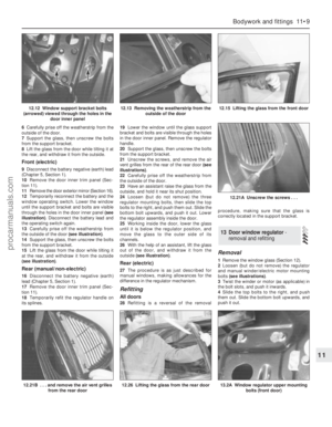 186
186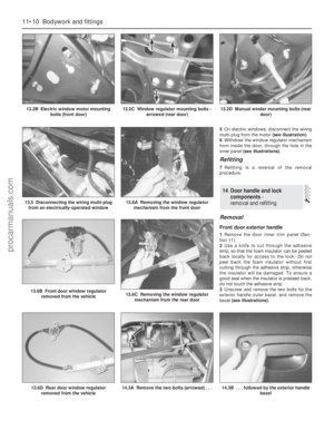 187
187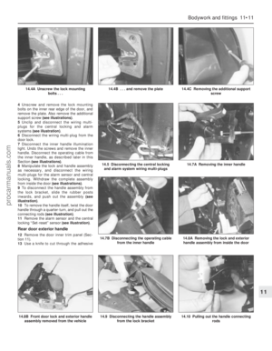 188
188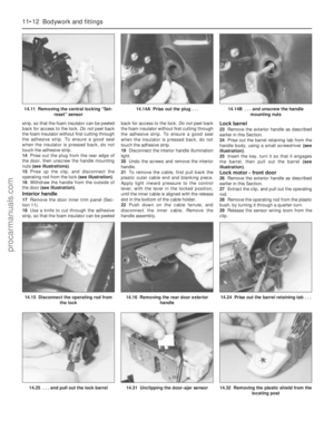 189
189 190
190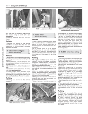 191
191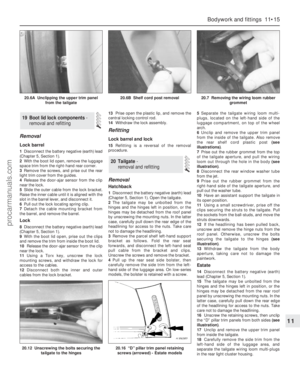 192
192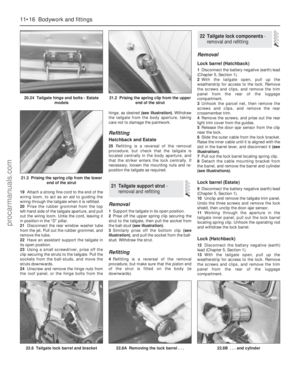 193
193 194
194 195
195 196
196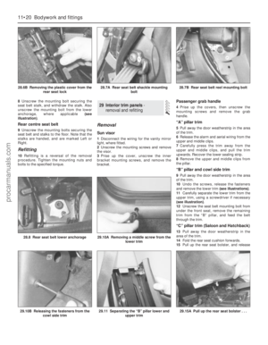 197
197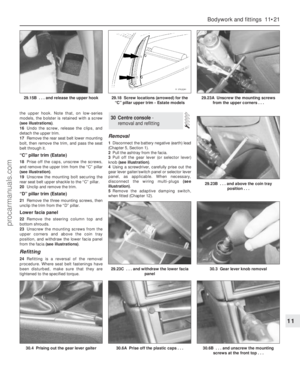 198
198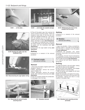 199
199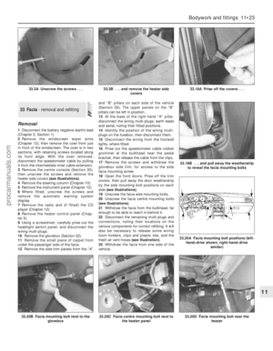 200
200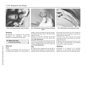 201
201 202
202 203
203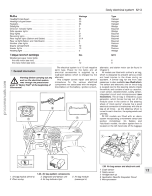 204
204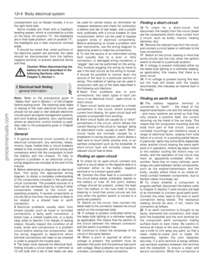 205
205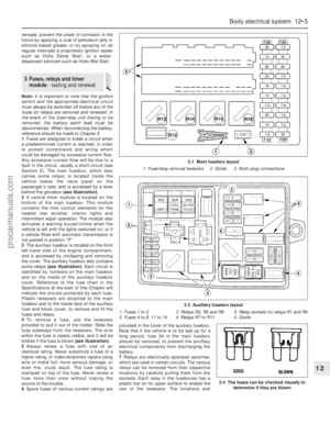 206
206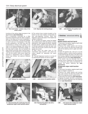 207
207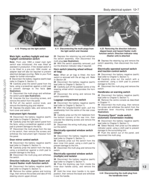 208
208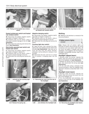 209
209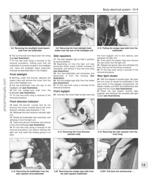 210
210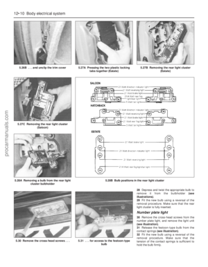 211
211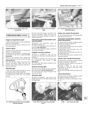 212
212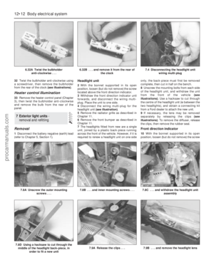 213
213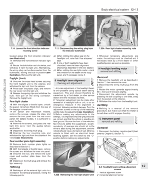 214
214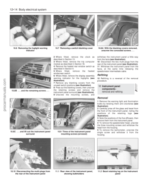 215
215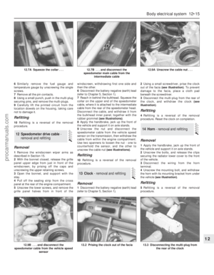 216
216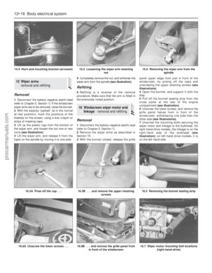 217
217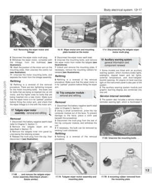 218
218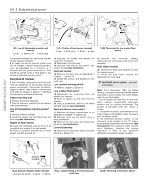 219
219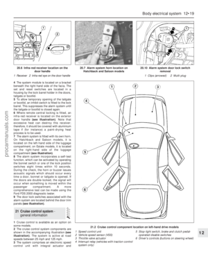 220
220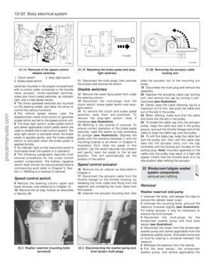 221
221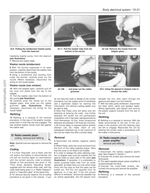 222
222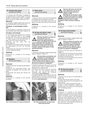 223
223 224
224 225
225 226
226 227
227 228
228 229
229 230
230 231
231 232
232 233
233 234
234 235
235 236
236 237
237 238
238 239
239 240
240 241
241 242
242 243
243 244
244 245
245 246
246 247
247 248
248 249
249 250
250 251
251 252
252 253
253 254
254 255
255 256
256 257
257 258
258 259
259 260
260 261
261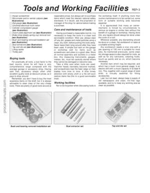 262
262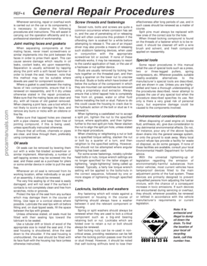 263
263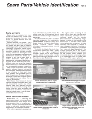 264
264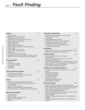 265
265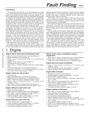 266
266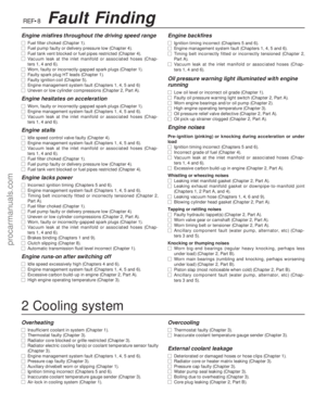 267
267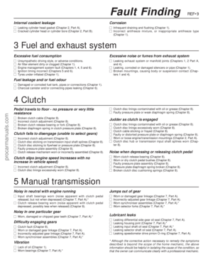 268
268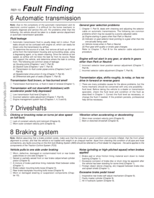 269
269 270
270 271
271 272
272 273
273 274
274 275
275 276
276 277
277 278
278