Page 145 of 279
 is missing - this
step in the")
passes the sensor tip, a signal is generated,
which is used by the ECU to determine engine
speed.
4The ridge between the 35th and 36th holes
(corresponding to 90° BTDC) is missing - this
step in the incoming signals is used by the
ECU to determine crankshaft (ie, piston)
position.
Camshaft position sensor
5This is bolted to the rear left-hand end of
the cylinder head, to register with a lobe on
the inlet camshaft. It functions in the same
way as the crankshaft speed/position sensor,
producing a series of pulses (corresponding
to No 1 cylinder at 46° ATDC); this gives the
ECU a reference point, to enable it to
determine the firing order, and operate the
injectors in the appropriate sequence.
Coolant temperature sensor
6This component, which is screwed into the
top of the thermostat housing, is an NTC
(Negative Temperature Coefficient) thermistor
- that is, a semi-conductor whose electrical
resistance decreases as its temperature
increases. It provides the ECU with a
constantly-varying (analogue) voltage signal,
corresponding to the temperature of the
engine coolant. This is used to refine the
calculations made by the ECU, when
determining the correct amount of fuel
required to achieve the ideal air/fuel mixture
ratio.
Intake air temperature sensor
7This component, which is screwed into the
underside of the air intake resonator, is also an
NTC thermistor - see the previous paragraph -
providing the ECU with a signal corresponding
to the temperature of air passing into the
engine. This is used to refine the calculations
made by the ECU, when determining the
correct amount of fuel required to achieve the
ideal air/fuel mixture ratio.
Throttle potentiometer
8This is mounted on the end of the throttle
valve spindle, to provide the ECU with a
constantly-varying (analogue) voltage signal
corresponding to the throttle opening. This
allows the ECU to register the driver’s input
when determining the amount of fuel required
by the engine.
Vehicle speed sensor
9This component is a Hall-effect generator,
mounted on the transmission’s speedometer
drive. It supplies the ECU with a series of
pulses corresponding to the vehicle’s road
speed, enabling the ECU to control features
such as the fuel shut-off on the overrun, and
to provide information for the trip computer,
adaptive damping and cruise control systems
(where fitted).
Power steering pressure switch
10This is a pressure-operated switch,
screwed into the power steering system’shigh-pressure pipe. Its contacts are normally
closed, opening when the system reaches the
specified pressure - on receiving this signal,
the ECU increases the idle speed, to
compensate for the additional load on the
engine.
Exhaust gas pressure differential
sensor
11This component measures the difference
in pressure of the exhaust gases across a
venturi (restriction) in the Exhaust Gas
Recirculation (EGR) system’s pipe, and sends
the ECU a voltage signal corresponding to the
pressure difference.
Oxygen sensor
12The oxygen sensor in the exhaust system
provides the ECU with constant feedback -
“closed-loop” control - which enables it to
adjust the mixture to provide the best possible
conditions for the catalytic converter to
operate.
13The sensor has a built-in heating element
which is controlled by the ECU, in order to
bring the sensor’s tip to an efficient operating
temperature as rapidly as possible. The
sensor’s tip is sensitive to oxygen, and sends
the ECU a varying voltage depending on the
amount of oxygen in the exhaust gases. If the
intake air/fuel mixture is too rich, the exhaust
gases are low in oxygen, so the sensor sends
a low-voltage signal, the voltage rising as the
mixture weakens and the amount of oxygen in
the exhaust gases rises. Peak conversion
efficiency of all major pollutants occurs if the
intake air/fuel mixture is maintained at the
chemically-correct ratio for the complete
combustion of petrol, of 14.7 parts (by weight)
of air to 1 part of fuel (the “stoichiometric”
ratio). The sensor output voltage alters sharply
around this point, the ECU using the signal
change as a reference point, and correcting
the air/fuel mixture by altering the fuel injector
pulse width.
Air conditioning system
14Two pressure-operated switches and the
compressor clutch solenoid are connected to
the ECU, to enable it to determine how the
system is operating. The ECU can increase
idle speed or switch off the system, as
necessary, so that normal vehicle operation
and driveability are not impaired. See Chapter
3 for further details, but note that diagnosis
and repair should be left to a dealer service
department or air conditioning specialist.
Automatic transmission
15In addition to the driver’s controls, the
transmission has a speed sensor, a fluid
temperature sensor (built into the solenoid
valve unit), and a selector lever position
sensor. All of these are connected to the ECU,
to enable it to control the transmission
through the solenoid valve unit. See Part B of
Chapter 7 for further details.
Testing
ECU (Electronic Control Unit)
16 Do notattempt to “test” the ECU with any
kind of equipment. If it is thought to be faulty,
take the vehicle to a Ford dealer for the entire
electronic control system to be checked using
the proper diagnostic equipment. Only if all
other possibilities have been eliminated should
the ECU be considered at fault, and replaced.
Air mass meter
17Testing of this component is beyond the
scope of the DIY mechanic, and should be left
to a Ford dealer.
Crankshaft speed/position sensor
18Unplug the electrical connector from the
sensor.
19Using an ohmmeter, measure the
resistance between the sensor terminals.
Compare this reading to the one listed in the
Specifications Section at the beginning of this
Chapter. If the indicated resistance is not
within the specified range, renew the sensor.
20Plug in the sensor’s electrical connector
on completion.
Camshaft position sensor
21The procedure is as described in
paragraphs 18 to 20 above.
Coolant temperature sensor
22Refer to Chapter 3.
Intake air temperature sensor
23Unplug the electrical connector from the
sensor.
24Using an ohmmeter, measure the
resistance between the sensor terminals.
Depending on the temperature of the sensor
tip, the resistance measured will vary, but it
should be within the broad limits given in the
Specifications Section of this Chapter. If the
sensor’s temperature is varied - by placing it
in a freezer for a while, or by warming it gently
- its resistance should alter accordingly.
25If the results obtained show the sensor to
be faulty, renew it.
Throttle potentiometer
26Remove the plenum chamber (see
Chapter 4) and unplug the potentiometer’s
electrical connector.
27Using an ohmmeter, measure the
resistance between the unit’s terminals - first
between the centre terminal and one of the
outer two, then from the centre to the
remaining outer terminal. The resistance
should be within the limits given in the
Specifications Section of this Chapter, and
should alter smoothlyas the throttle valve is
moved from the fully-closed (idle speed)
position to fully open and back again.
28If the resistance measured is significantly
different from the specified value, if there are
any breaks in continuity, or if the reading
fluctuates erratically as the throttle is
operated, the potentiometer is faulty, and
must be renewed.
Emissions control systems 6•11
6
procarmanuals.com
Page 146 of 279

Vehicle speed sensor
29Testing of this component is beyond the
scope of the DIY mechanic, and should be left
to a Ford dealer.
Power steering pressure switch
30Unplug the electrical connector from the
sensor.
31Using an ohmmeter, measure the
resistance between the switch terminals. With
the engine switched off, or idling with the
roadwheels in the straight-ahead position,
little or no resistance should be measured.
With the engine running and the steering on
full-lock, the pressure increase in the system
should open the switch contacts, so that
infinite resistance is now measured.
32If the results obtained show the switch to
be faulty, renew it.
Exhaust gas pressure differential
sensor
33Testing of this component is beyond the
scope of the DIY mechanic, and should be left
to a Ford dealer.
Oxygen sensor
34Testing of this component can be done
only by attaching special diagnostic
equipment to the sensor wiring, and checking
that the voltage varies from low to high values
when the engine is running; do notattempt to
“test” any part of the system with anything
other than the correct test equipment. This is
beyond the scope of the DIY mechanic, and
should be left to a Ford dealer.
Removal and refitting
General
35Before disconnecting any of these
components, always disconnect the power by
uncoupling the battery terminals, negative
(earth) lead first - see Section 1 of Chapter 5.
ECU (Electronic Control Unit)
Note:The ECU is fragile. Take care not to
drop it or subject it to any other kind of
impact, and do not subject it to extremes of
temperature, or allow it to get wet.
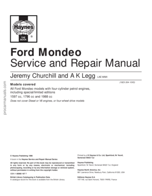
36Carefully prise the power steering fluid
reservoir upwards out of its clip on the
suspension mounting. Unscrew the ECU
connector’s retaining bolt, and unplug the
connector (see illustrations).
37Working in the passenger compartment,
unscrew the retaining bolt and withdraw the
mounting bracket (see illustration).
38Lifting the ECU to release it from the
bulkhead carrier bracket, withdraw the unit
(see illustration).
39Refitting is the reverse of the removal
procedure. Whenever the ECU (or battery) is
disconnected, the information relating to idle
speed control and other operating values will
be lost from its memory until the unit has re-
programmed itself; until then, there may be
surging, hesitation, erratic idle and a
generally-inferior level of performance. To
allow the ECU to re-learn these values, start
the engine and run it as close to idle speed as
possible until it reaches its normal operatingtemperature, then run it for approximately two
minutes at 1200 rpm. Next, drive the vehicle
as far as necessary - approximately 5 miles of
varied driving conditions is usually sufficient -
to complete the re-learning process.
Air mass meter
40Releasing its wire clip, unplug the meter’s
electrical connector (see illustration).
41Release the clips and lift the air cleaner
cover, then release the two smaller clips and
detach the meter from the cover (see
illustration).
42Slacken the clamp securing the meter to
the resonator hose, and withdraw the meter.
43Refitting is the reverse of the removal
procedure. Ensure that the meter and air
cleaner cover are seated correctly and securely
fastened, so that there are no air leaks.
Crankshaft speed/position sensor
44Refer to Chapter 5.
Camshaft position sensor
45Remove the air mass meter and resonator
(refer to Chapter 4) to gain access to the
sensor (see illustration). Release the fuel
feed and return hoses from their clip.
46Releasing its wire clip, unplug the
sensor’s electrical connector. Remove the
retaining screw, and withdraw the sensor from
the cylinder head; be prepared for slight oil
loss.
47Refitting is the reverse of the removal
procedure, noting the following points:
6•12 Emissions control systems
4.36A Unclip and lift power steering fluid
reservoir - take care not to spill fluid . . .4.36B . . . unscrew bolt (arrowed) to
release ECU’s electrical connector4.37 Unscrew retaining bolt and withdraw
ECU’s mounting bracket . . .
4.40 Unplugging the air mass meter’s
electrical connector . . .4.38 . . . then lift ECU to disengage it, and
withdraw it4.41 . . . release clips to separate meter
from air cleaner cover
procarmanuals.com
Page 147 of 279
 Apply petroleum jelly or clean engine oil
to the sensor’s sealing O-ring.
(b) Locate the sensor fully in the cylinder
head, and wipe off any surplus lubricant
before securing it.
(c) Tighten the")
(a) Apply petroleum jelly or clean engine oil
to the sensor’s sealing O-ring.
(b) Locate the sensor fully in the cylinder
head, and wipe off any surplus lubricant
before securing it.
(c) Tighten the screw to the specified torque
wrench setting.
Coolant temperature sensor
48Refer to Chapter 3, Section 6.
Intake air temperature sensor
49Remove the air mass meter and resonator
(refer to Chapter 4) to gain access to the
sensor (see illustration).
50Releasing its clip, unplug the sensor’s
electrical connector, then unscrew the sensor
from the resonator.
51Refitting is the reverse of the removal
procedure. Tighten the sensor to the specified
torque wrench setting; if it is overtightened, its
tapered thread may crack the resonator.
Throttle potentiometer
52Remove the plenum chamber (see
Chapter 4). Releasing its wire clip, unplug the
large electrical connector (next to the fuel
pressure regulator).
53Releasing its wire clip, unplug the
potentiometer’s electrical connector. Remove
the retaining screws, and withdraw the unit
from the throttle housing (see illustration). Do
notforce the sensor’s centre to rotate past itsnormal operating sweep; the unit will be
seriously damaged.
54Refitting is the reverse of the removal
procedure, noting the following points:
(a) Ensure that the potentiometer is correctly
orientated, by locating its centre on the D-
shaped throttle shaft (throttle closed), and
aligning the potentiometer body so that
the bolts pass easily into the throttle
housing.
(b) Tighten the screws evenly and securely
(but do not overtighten them, or the
potentiometer body will be cracked).
Vehicle speed sensor
55The sensor is mounted at the base of the
speedometer drive cable, and is removed with
the speedometer drive pinion (see
illustration). Refer to the relevant Section of
Chapter 7, Part A or B, as applicable.
Power steering pressure switch
56Releasing its clip, unplug the switch’s
electrical connector, then unscrew the switch
(see illustration). Place a wad of rag
underneath, to catch any spilt fluid. If a
sealing washer is fitted, renew it if it is worn or
damaged.
57Refitting is the reverse of the removal
procedure; tighten the switch securely, then
top-up the fluid reservoir (see Chapter 1) to
replace any fluid lost from the system, and
bleed out any trapped air (see Chapter 10,
Section 33).
Exhaust gas pressure differential
sensor
Note:See also Section 6, illustration 6.21.
58If better access is required, remove the
resonator (see Chapter 4).
59Releasing its wire clip, unplug the
sensor’s electrical connector. Remove the
two retaining screws, withdraw the unit from
the bulkhead mounting bracket, then
disconnect the two vacuum hoses. Note that
the hoses are of different sizes, to ensure that
they cannot be mixed up on reconnection.
60Check the condition of both hoses, and
renew them if necessary (see Chapter 1).
61Refitting is the reverse of the removal
procedure. Ensure that the hoses are securely
connected to the correct unions.
Oxygen sensor
Note:The sensor is delicate, and will not work
if it is dropped or knocked, if its power supply
is disrupted, or if any cleaning materials are
used on it.
62Release the sensor’s electrical connector
from its bracket on the engine/transmission
front mounting, and unplug it to disconnect
the sensor (see illustration).
63Raising and supporting the front of the
vehicle if required to remove the sensor from
underneath, unscrew the sensor from the
exhaust system front downpipe; collect the
sealing washer (where fitted).
64On refitting, clean the sealing washer
Emissions control systems 6•13
6
4.56 Power steering pressure switch is
screwed into pipe at right-hand rear end of
engine4.62 Oxygen sensor is screwed into
exhaust system front downpipe . . .
4.49 Intake air temperature sensor
(arrowed) is screwed into underside of air
intake resonator4.53 Throttle potentiometer is secured by
two screws (arrowed)
4.55 Vehicle speed sensor “A”, with its
electrical connector “B”
4.45 Camshaft position sensor is located
at left-hand rear end of cylinder head
procarmanuals.com
Page 148 of 279
 and renew it if it is damaged or
worn. Apply a smear of anti-seize compound
to the sensor’s threads, to prevent them from
welding themselves to the downpipe in
service. Refit the sens")
(where fitted) and renew it if it is damaged or
worn. Apply a smear of anti-seize compound
to the sensor’s threads, to prevent them from
welding themselves to the downpipe in
service. Refit the sensor, tightening it to its
specified torque wrench setting; a slotted
socket will be required to do this (see
illustration). Reconnect the wiring and refit
the connector plug.
General description
1This system is fitted to minimise the escape
of unburned hydrocarbons into the
atmosphere. The fuel tank filler cap is sealed,
and a charcoal canister is mounted
underneath the tank, to collect and store
petrol vapours generated in the tank when the
vehicle is parked. When the engine is running,
the vapours are cleared from the canister
(under the control of the ECU via the canister-
purge solenoid valve) into the inlet tract, to be
burned by the engine during normal
combustion - see illustration 2.1A.
2To ensure that the engine runs correctly
when it is cold and/or idling, and to protect
the catalytic converter from the effects of an
over-rich mixture, the canister-purge solenoid
valve is not opened by the ECU until the
engine is fully warmed-up and running under
part-load; the solenoid valve is then switched
on and off, to allow the stored vapour to pass
into the inlet.
Checking
3Poor idle, stalling and poor driveability can
be caused by an inoperative canister-purge
solenoid valve, a damaged canister, split or
cracked hoses, or hoses connected to the
wrong fittings. Check the fuel filler cap for a
damaged or deformed gasket.
4Fuel loss or fuel odour can be caused by
liquid fuel leaking from fuel lines, a cracked or
damaged canister, an inoperative canister-purge solenoid valve, and disconnected,
misrouted, kinked or damaged vapour or
control hoses.
5Inspect each hose attached to the canister
for kinks, leaks and cracks along its entire
length. Repair or renew as necessary.
6Inspect the canister. If it is cracked or
damaged, renew it. Look for fuel leaking from
the bottom of the canister. If fuel is leaking,
renew the canister, and check the hoses and
hose routing.
7If the canister-purge solenoid valve is
thought to be faulty, unplug its electrical
connector and disconnect its vacuum hoses.
Connect a battery directly across the valve
terminals. Check that air can flow through the
valve passages when the solenoid is thus
energised, and that nothing can pass when the
solenoid is not energised. Alternatively,
connect an ohmmeter to measure the
resistance across the solenoid terminals, and
compare this reading to the one listed in the
Specifications Section at the beginning of this
Chapter. Renew the solenoid valve if it is faulty.
8Further testing should be left to a dealer
service department.
Component renewal
Charcoal canister-purge solenoid
valve
9If better access is required, remove the
plenum chamber (see Chapter 4). Disconnect
the battery negative (earth) lead - see Sec-
tion 1 of Chapter 5.10Unplug the valve’s electrical connector
(see illustration). Unclip the valve from the
bulkhead, then disconnect its vacuum hoses
and withdraw it.
11Refitting is the reverse of the removal
procedure.
Charcoal canister - Saloon and
Hatchback models
Note:Read through this procedure carefully
before starting work, and ensure that the
equipment is available that is required to carry
it out safely and with minimum risk of damage,
and to align the crossmember with sufficient
accuracy on reassembly.
12Remove the fuel tank (see Chapter 4).
13Ensure that the rear of the vehicle’s body
is supported securely on axle stands, then
support the rear suspension crossmember
with a jack. Remove the roadwheels and
unscrew the rear suspension strut top
mounting bolts (two per side - see Chapter
10).
14Use white paint or similar (do not use a
sharp-pointed scriber, which might break the
underbody protective coating and cause
rusting) to mark the exact relationship of the
crossmember to the underbody. Unscrew the
four mounting bolts (see illustration). Lower
the crossmember approximately 3 inches (75
mm) on the jack, and support it securely.
Warning: DO NOT place any part
of your body under the vehicle
when it is supported only by a
jack!
5 EVAPorative emissions control
(EVAP) system -
general information, checking
and component renewal
6•14 Emissions control systems
4.64 . . . slotted socket will be required to
tighten sensor with a torque wrench5.10 Charcoal canister-purge solenoid
valve (arrowed) is clipped to bulkhead
behind engine5.14 Support rear suspension
crossmember on jack, and remove
mounting bolts (arrowed) . . .
5.15 . . . lower crossmember by 3 inches,
and unscrew charcoal canister assembly
rear retaining bolts (arrowed) . . .5.16 . . . unplug hoses (arrowed) from
canister assembly . . .
procarmanuals.com
Page 149 of 279
.
16Unplug the two hoses from the canister
assembly, noting which way round they are
fitted (see illustration).
17Unscrew")
15Unscrew the two rearmost canister
assembly retaining bolts (see illustration).
16Unplug the two hoses from the canister
assembly, noting which way round they are
fitted (see illustration).
17Unscrew the canister assembly’s front
retaining bolt (see illustration). Withdraw the
canister assembly.
18Release the clip, and drive out the pin to
separate the canister from its bracket (see
illustration).
19On reassembly, refit the canister to its
bracket and refit the assembly to the vehicle,
tightening the retaining bolts securely, and
ensuring that the two hoses are securely
reconnected to their original unions.
20Offer up the crossmember and refit the
crossmember bolts, tightening them only
lightly at this stage.
21The crossmember must now be aligned
on the underbody. Ford specify the use of
service tool 15-097, which is a pair of tapered
guides, with attachments to hold them in the
crossmember as it is refitted (see
illustration). However, since the working
diameter of these tools is 20.4 mm, and since
the corresponding aligning holes in the
crossmember and underbody are 21 mm and
22 mm in diameter, there is a significant in-
built tolerance possible in the crossmember’s
alignment, even if the correct tools are used. If
these tools are not available, align the
crossmember by eye, centring thecrossmember aligning holes on those of the
underbody, and using the marks made on
removal for assistance. Alternatively, use a
tapered drift such as a clutch-aligning tool, or
a deep socket spanner of suitable size.
22Once the crossmember is aligned as
precisely as possible, tighten its bolts to the
specified torque (see Chapter 10
Specifications) without disturbing its position
(see illustration). Recheck the alignment
once all the bolts are securely tightened.
23The remainder of the refitting procedure is
the reverse of removal.
24Remember that, since the rear suspension
crossmember has been disturbed, the wheel
alignment and steering angles must be
checked fully and carefully as soon as
possible, with any necessary adjustments
being made. This operation is best carried out
by an experienced mechanic using proper
checking equipment; the vehicle should
therefore be taken to a Ford dealer or similar
for attention.
Charcoal canister - Estate models
25Disconnect the battery negative (earth)
lead - see Section 1 of Chapter 5.
26Raise the rear of the vehicle, and support
it securely on axle stands.
Warning: DO NOT place any part
of your body under the vehicle
when it is supported only by a
jack!27Disconnect the two hoses from the
canister assembly, noting which way round
they are fitted.
28Unscrew the canister assembly retaining
bolt and withdraw the assembly, unclipping it
from the front mounting.
29Remove the plastic cover, and drive out
the pin to separate the canister from its
bracket (see illustration).
30On refitting, secure the canister to its
bracket, and refit the assembly to the vehicle.
Tighten the retaining bolt securely, and ensure
that the two hoses are securely reconnected
to their original unions.
General information
1To reduce oxides of nitrogen (NOx)
emissions, some of the exhaust gases are
recirculated through the EGR valve to the inlet
manifold. This has the effect of lowering
combustion temperatures.
2The system consists of the EGR valve, the
EGR exhaust gas pressure differential sensor,
the EGR solenoid valve, the ECU, and various
sensors - see illustration 2.1A. The ECU is
programmed to produce the ideal EGR valve
lift for each operating condition.
Checking
EGR valve
3Start the engine and allow it to idle.
4Detach the vacuum hose from the EGR
valve, and attach a hand vacuum pump in its
place.
5Apply vacuum to the EGR valve. Vacuum
should remain steady, and the engine should
run poorly.
(a) If the vacuum doesn’t remain steady and
the engine doesn’t run poorly, renew the
EGR valve and recheck it.
(b) If the vacuum remains steady but the
engine doesn’t run poorly, remove the
6 Exhaust Gas Recirculation
(EGR) system-
general information, checking
and component renewal
Emissions control systems 6•15
6
5.22 . . . ensure aligned crossmember
does not move - Ford tools used here -
while mounting bolts are tightened5.29 Charcoal canister assembly - Estate
models - showing plastic cover (arrowed)
and pin securing canister to mounting
bracket
5.17 . . . and remove front retaining bolt
(arrowed) to release canister assembly -
Saloon and Hatchback models5.18 Release clip and drive out pin to
separate canister from mounting bracket5.21 Refitting rear suspension crossmember
with Ford service tools (arrowed) in place to
align it with underbody . . .
procarmanuals.com
Page 150 of 279

EGR valve, and check the valve and the
inlet manifold for blockage. Clean or
renew parts as necessary, and recheck.
EGR system
6Any further checking of the system requires
special tools and test equipment. Take the
vehicle to a dealer service department for
checking.
Component renewal
Note:These components will be very hot
when the engine is running. Always allow the
engine to cool down fully before starting work,
to prevent the possibility of burns.
EGR valve
7Disconnect the battery negative (earth) lead
- see Section 1 of Chapter 5.
8Remove the air mass meter and resonator -
refer to Chapter 4.
9Detach the vacuum hose, unscrew the
sleeve nut securing the EGR pipe to the valve,
remove the two valve mounting bolts, and
withdraw the valve from the inlet manifold
(see illustrations). Ensure that the end of the
pipe is not damaged or distorted as the valve
is withdrawn, and note the valve’s gasket; this
must be renewed whenever the valve is
disturbed.
10Note that the metal pipe from the valve to
the manifold itself should not be disturbed - it
is not available separately from the manifold.However, check whenever the manifold is
removed that the pipe’s end fitting is securely
fastened (see illustration).
11Check the valve for sticking and heavy
carbon deposits. If such is found, clean the
valve or renew it.
12Refitting is the reverse of the removal
procedure. Apply a smear of anti-seize
compound to the sleeve nut threads, fit a new
gasket, and tighten the valve bolts to the
specified torque wrench setting.
EGR pipe
13Disconnect the battery negative (earth)
lead - see Section 1 of Chapter 5.
14Remove the air mass meter and resonator
- refer to Chapter 4.
15Unbolt the exhaust manifold heat shield
and remove both parts, or move them aside
as required to reach the end of the EGR pipe.
Unscrew the sleeve nut securing the pipe to
the exhaust manifold (see illustration).
16Undo the two screws securing the pipe to
the ignition coil bracket, then disconnect the
two vacuum hoses - note that these are of
different sizes, to ensure that they cannot be
mixed up on reconnection. Unscrew the
sleeve nut securing the EGR pipe to the valve
(see illustration). Withdraw the pipe.
17Check the condition of both hoses, and
renew them if necessary (see Chapter 1). Note
that if the exhaust gases have been backfiring
excessively - eg, due to a blocked exhaust
system - both hoses must be renewed, andtheir connections on the pipe must be cleaned
thoroughly.
18Refitting is the reverse of the removal
procedure; ensure that the hoses are securely
connected to the correct unions. Apply a
smear of anti-seize compound to the sleeve
nut threads, tighten the nuts securely, and
tighten the two screws to their specified
torque wrench setting.
EGR exhaust gas pressure differential
sensor
19Refer to Section 4 of this Chapter.
EGR solenoid valve
Note:This component can be identified by its
larger top and its two fastening screws. Do not
confuse it with the adjacent pulse-air solenoid
valve, especially when reconnecting vacuum
hoses.
20Disconnect the battery negative (earth)
lead - see Section 1 of Chapter 5.
21Remove the air mass meter and resonator
- refer to Chapter 4. If better access is
required, remove the plenum chamber also
(see illustration).
22Releasing its wire clip, unplug the
electrical connector from the valve. Remove
the two retaining screws, and withdraw the
valve from the bulkhead mounting bracket,
then label and disconnect the two vacuum
hoses.
23Refitting is the reverse of the removal
procedure; ensure that the hoses are correctly
reconnected.
6•16 Emissions control systems
6.9A Disconnecting vacuum hose from
Exhaust Gas Recirculation (EGR) valve . . .6.9B . . . unscrew EGR pipe sleeve nut and
remove bolts (arrowed) to release valve
from inlet manifold6.10 Check end fitting of EGR pipe into
inlet manifold whenever manifold is
removed, but do not disturb
6.15 Unbolt exhaust manifold heat shield,
and unscrew sleeve nut (arrowed) securing
EGR pipe to exhaust manifold . . .6.16 . . . undo screws “A” and sleeve
nut “B”, then disconnect hoses “C” - note
different sizes - to release EGR pipe6.21 EGR solenoid valve “A” and EGR
exhaust gas pressure differential sensor
“B”, located on bulkhead mounting bracket
procarmanuals.com
Page 151 of 279

General information
1This system consists of the pulse-air
solenoid valve, the pulse-air valve itself,
contained in the filter housing, and the piping
- see illustration 2.1A. It injects filtered air
directly into the exhaust ports, using the
pressure variations in the exhaust gases to
draw air through from the filter housing; air will
flow into the exhaust only when its pressure is
below atmospheric. The pulse-air valve can
allow gases to flow only one way, so there is
no risk of hot exhaust gases flowing back into
the filter.
2The system’s primary function is raise
exhaust gas temperatures on start-up, thus
reducing the amount of time taken for the
oxygen sensor and catalytic converter to
reach operating temperature. Until this
happens, the system reduces emission of
unburned hydrocarbon particles (HC) and
carbon monoxide (CO) by ensuring that a
considerable proportion of these substances
remaining in the exhaust gases after
combustion are burned up, either in the
manifold itself or in the catalytic converter.
3To ensure that the system does not upset
the smooth running of the engine under
normal driving conditions, it is linked by the
pulse-air solenoid valve to the ECU, so that it
only functions during engine warm-up, when
the oxygen sensor is not influencing the
fuel/air mixture ratio.
Checking
4Poor idle, stalling, backfiring and poor
driveability can be caused by a fault in the
system.
5Inspect the vacuum pipe/hose connected
between the filter housing and the solenoid
valve for kinks, leaks and cracks along its
entire length. Repair or renew as necessary.
6Inspect the filter housing and piping. If
either is cracked or damaged, renew it.7If the pulse-air solenoid valve is thought to
be faulty, unplug its electrical connector and
disconnect its vacuum hoses. Connect a
battery directly across the valve terminals,
and check that air can flow through the valve
passages when the solenoid is thus
energised, and that nothing can pass when
the solenoid is not energised. Alternatively,
connect an ohmmeter to measure the
resistance across the valve terminals, and
compare this reading to the one listed in the
Specifications Section at the beginning of this
Chapter. Renew the solenoid valve if it is
faulty.
8Further testing should be left to a dealer
service department.
Component renewal
Pulse-air solenoid valve
Note:This component can be identified by its
smaller top and its clip fastening. Do not
confuse it with the adjacent EGR solenoid
valve, especially when reconnecting vacuum
hoses.
9Disconnect the battery negative (earth) lead
- see Section 1 of Chapter 5.
10Remove the air mass meter and resonator
- refer to Chapter 4. If better access is
required, remove the plenum chamber also
(see illustration).
11Releasing its wire clip, unplug the
electrical connector, then use a small
screwdriver to release the clip securing the
valve to the bulkhead mounting bracket.Withdraw the valve, then label and disconnect
the two vacuum hoses.
12Refitting is the reverse of the removal
procedure; ensure that the hoses are correctly
reconnected.
Pulse-air filter housing
Note:This component, and those around it,
will be very hot when the engine is running.
Always allow the engine to cool down fully
before starting work, to prevent the possibility
of burns.
13Raise the front of the vehicle, and support
it securely on axle stands. Disconnect the
vacuum hose from the base of the filter
housing (see illustration).
14Disconnect the battery negative (earth)
lead - see Section 1 of Chapter 5.
15Unbolt the resonator support bracket
from the engine compartment front
crossmember, slacken the two clamp screws
securing the resonator to the air mass meter
and plenum chamber hoses, then swing the
resonator up clear of the thermostat housing
(see Chapter 4).
16Remove the screws securing the filter
housing to the piping, unscrew the mounting
bolt, then withdraw the housing (see
illustration).
17To dismantle the filter housing, undo the
four screws and separate the top from the
base of the housing; extract the foam filter,
and clean it in a suitable solvent (see
illustrations). If any of the housing’s
7 Pulse-air system -
general information
Emissions control systems 6•17
6
7.17A Remove four screws to release filter
housing top from base . . .7.17B . . .and withdraw foam filter for
cleaning, if required - note valve in base of
housing
7.10 Pulse-air solenoid valve (arrowed) is
located on bulkhead mounting bracket. It
can be identified by its smaller top and its
clip fastening - do not confuse it with the
adjacent EGR solenoid valve7.13 Disconnect vacuum hose from base
of pulse-air filter housing . . .7.16 . . . undo screws “A” to disconnect
piping from housing, and mounting
bolt “B” to release housing
procarmanuals.com
Page 152 of 279

components are worn or damaged, the
assembly must be renewed.
18Refitting is the reverse of the removal
procedure.
Pulse-air piping
Note:This component, and those around it,
will be very hot when the engine is running.
Always allow the engine to cool down fully
before starting work, to prevent the possibility
of burns.
19Disconnect the battery negative (earth)
lead - see Section 1 of Chapter 5.
20Remove the air mass meter and resonator
- refer to Chapter 4.
21Unbolt the exhaust manifold heat shield;
unclip the coolant hose to allow the upper
part to be withdrawn. Apply penetrating oil to
the EGR pipe sleeve nut, and to the pulse-air
system sleeve nuts.
22Remove the EGR pipe (see Section 6).
23Remove the screws securing the filter
housing to the piping - see illustration 7.16.
Unscrew the four sleeve nuts securing the
pipes into the exhaust manifold, and remove
the piping as an assembly, taking care not to
distort it (see illustration).
24Carefully clean the piping, particularly its
threads and those of the manifold, removing
all traces of corrosion, which might prevent
them seating properly, causing air leaks when
the engine is restarted.
25On refitting, insert the piping carefully into
the cylinder head ports, taking care not to
bend or distort it. Apply anti-seize compound
to the threads, and tighten the retaining sleeve
nuts while holding each pipe firmly in its port;
if a suitable spanner is available, tighten the
sleeve nuts to the specified torque wrench
setting.
26The remainder of the refitting procedure is
the reverse of removal.
Pulse-air filter housing and piping
assembly
Note:These components, and those around
them, will be very hot when the engine is
running. Always allow the engine to cool down
fully before starting work, to prevent the
possibility of burns.
27Disconnect the battery negative (earth)
lead - see Chapter 5, Section 1. Unbolt theresonator support bracket from the engine
compartment front crossmember. Slacken the
two clamp screws securing the resonator to
the air mass meter and plenum chamber
hoses, then swing the resonator up clear of
the thermostat housing (see Chapter 4).
28Drain the cooling system (see Chapter 1)
and disconnect the coolant hose and the
coolant pipe/hose from the thermostat
housing.
29Unbolt the exhaust manifold heat shield.
Apply penetrating oil to the EGR pipe sleeve
nut, and to the pulse-air system sleeve nuts.
30Remove the EGR pipe (see Section 6).
31Unscrew the filter housing mounting bolt.
Unscrew the four sleeve nuts securing the
pipes into the exhaust manifold and remove
the assembly, taking care not to distort it (see
illustration).
32Clean the piping, particularly its threads
and those of the manifold, removing all tracesof corrosion, which might prevent them
seating properly, causing air leaks when the
engine is restarted.
33On refitting, insert the piping carefully into
the cylinder head ports, taking care not to
bend or distort it. Apply anti-seize compound
to the threads, and tighten the retaining sleeve
nuts while holding each pipe firmly in its port;
if a suitable spanner is available, tighten the
sleeve nuts to the specified torque wrench
setting.
34The remainder of the refitting procedure is
the reverse of removal. Refill the cooling
system (see Chapter 1). Run the engine,
check for exhaust leaks, and check the
coolant level when it is fully warmed-up.
General information
1The crankcase ventilation system main
components are the oil separator mounted on
the front (radiator) side of the cylinder
block/crankcase, and the Positive Crankcase
Ventilation (PCV) valve set in a rubber
grommet in the separator’s left-hand upper
end. The associated pipework consists of a
crankcase breather pipe and two flexible
hoses connecting the PCV valve to a union on
the left-hand end of the inlet manifold, and a
crankcase breather hose connecting the
cylinder head cover to the air cleaner
assembly (see illustration). A small foam filter
in the air cleaner prevents dirt from being
drawn directly into the engine.
8 Positive Crankcase Ventilation
(PCV) system -
general information
6•18 Emissions control systems
7.23 Removing pulse-air piping - take care
not to bend or distort it7.31 Remove mounting bolt (arrowed) to
remove complete pulse-air assembly -
again, take care not to bend or distort
piping
8.1 Positive Crankcase Ventilation system
1 Oil separator
2 Gasket
3 Positive Crankcase Ventilation (PCV) valve4 Cylinder block/crankcase opening
5 Crankcase breather pipe and flexible hoses
procarmanuals.com
 1
1 2
2 3
3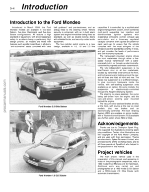 4
4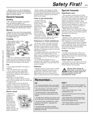 5
5 6
6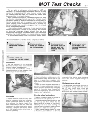 7
7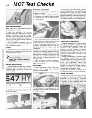 8
8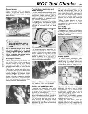 9
9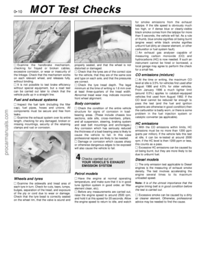 10
10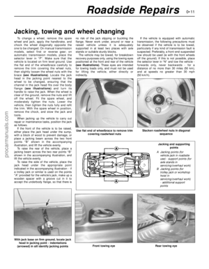 11
11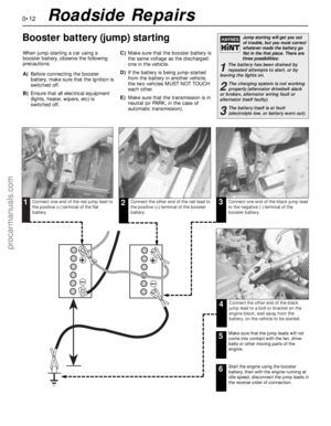 12
12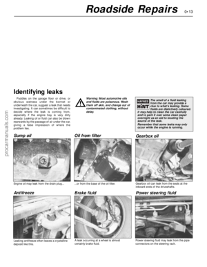 13
13 14
14 15
15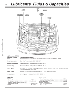 16
16 17
17 18
18 19
19 20
20 21
21 22
22 23
23 24
24 25
25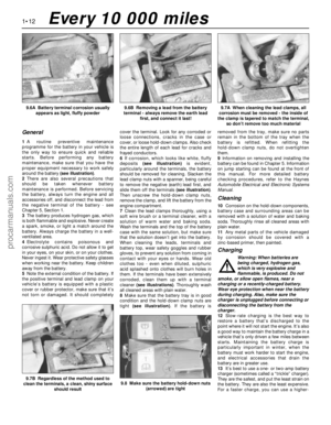 26
26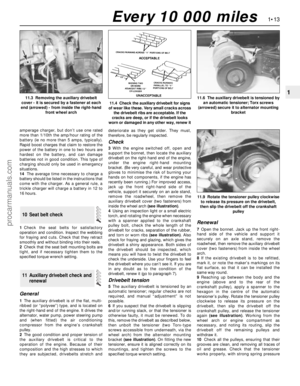 27
27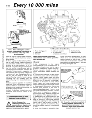 28
28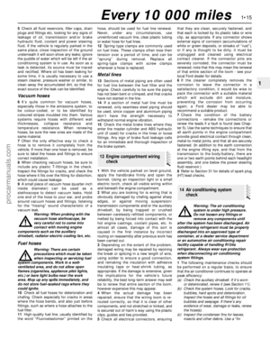 29
29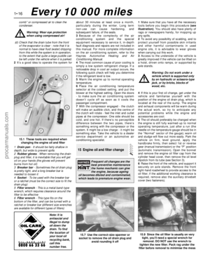 30
30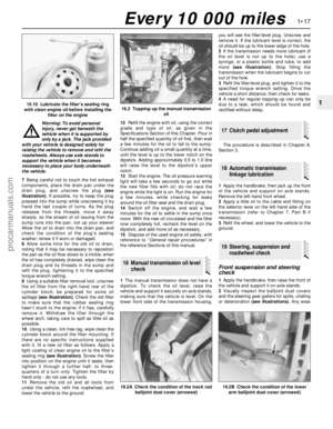 31
31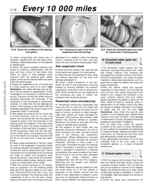 32
32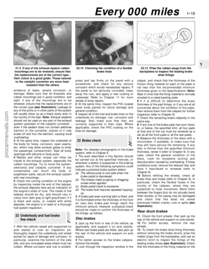 33
33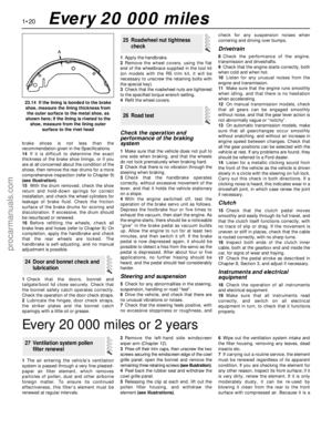 34
34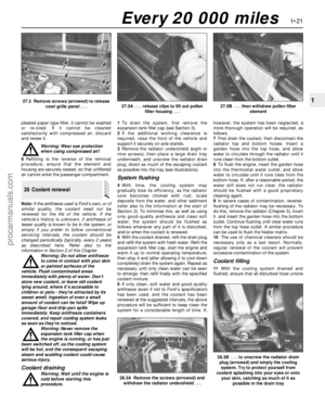 35
35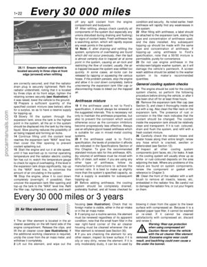 36
36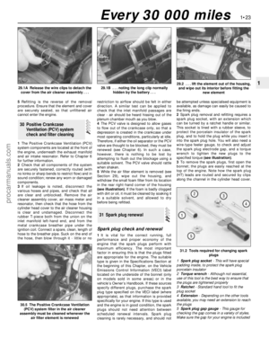 37
37 38
38 39
39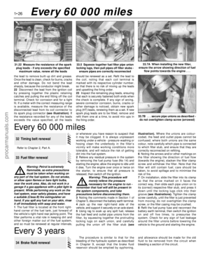 40
40 41
41 42
42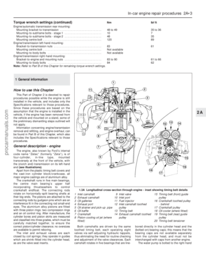 43
43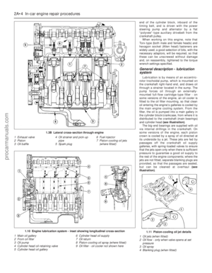 44
44 45
45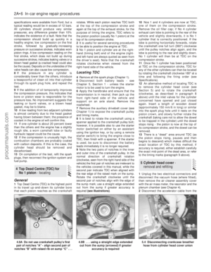 46
46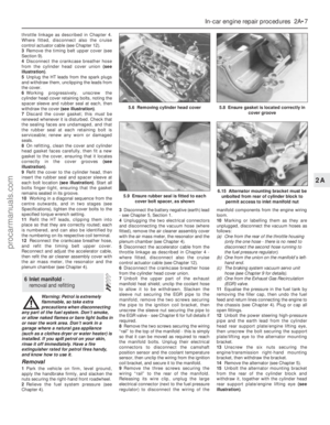 47
47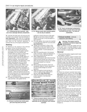 48
48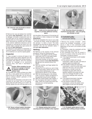 49
49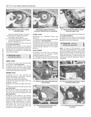 50
50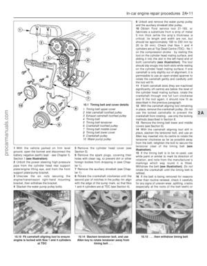 51
51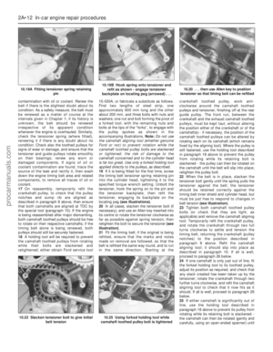 52
52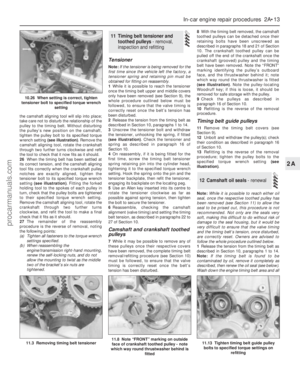 53
53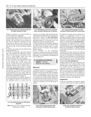 54
54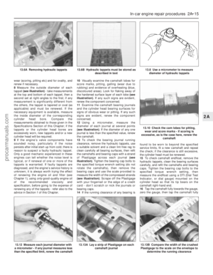 55
55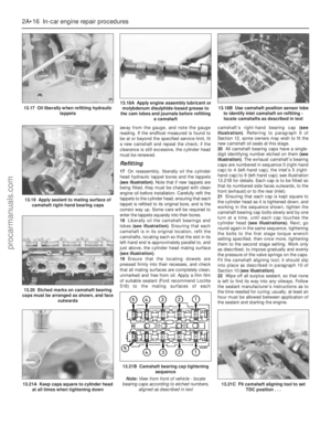 56
56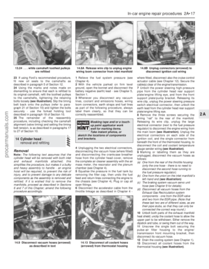 57
57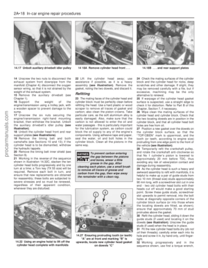 58
58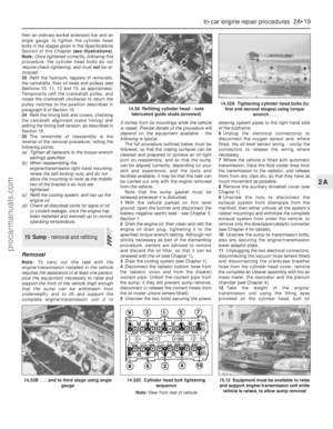 59
59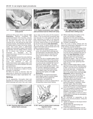 60
60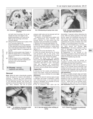 61
61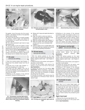 62
62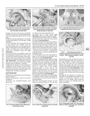 63
63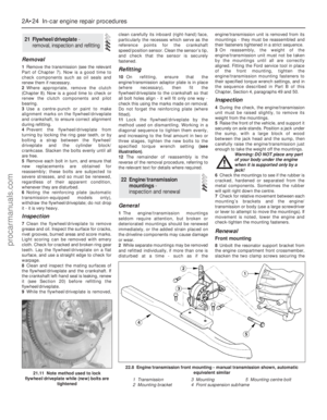 64
64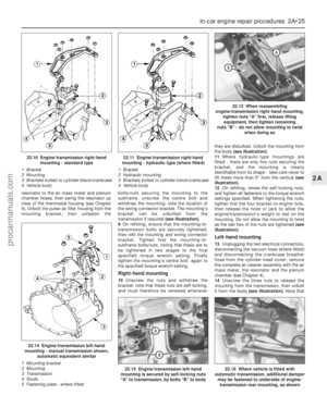 65
65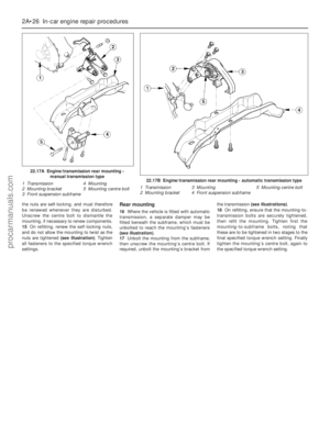 66
66 67
67 68
68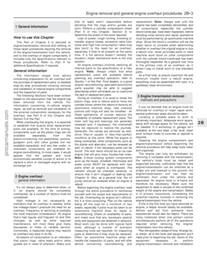 69
69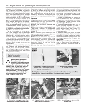 70
70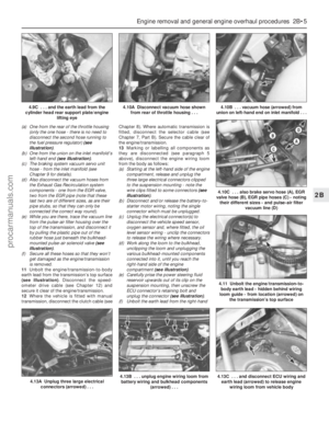 71
71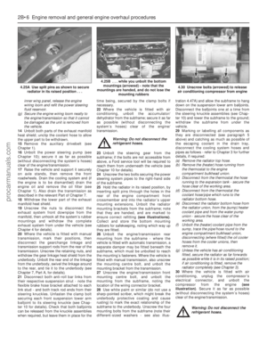 72
72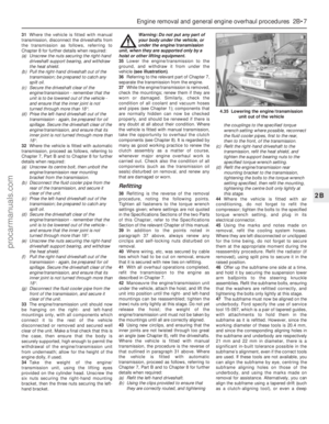 73
73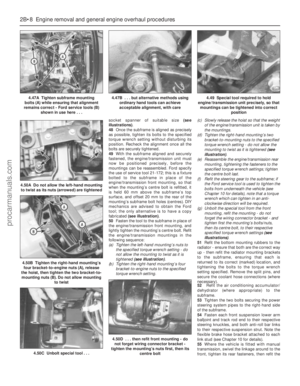 74
74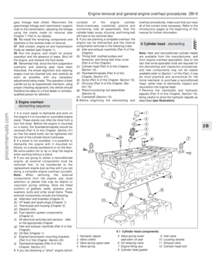 75
75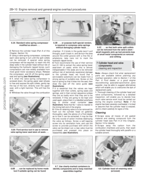 76
76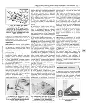 77
77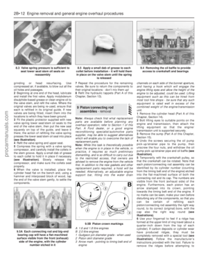 78
78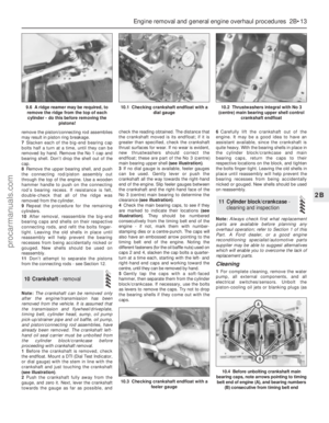 79
79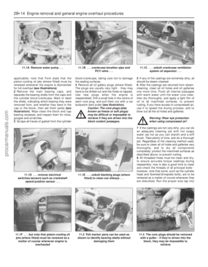 80
80 81
81 82
82 83
83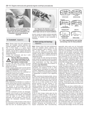 84
84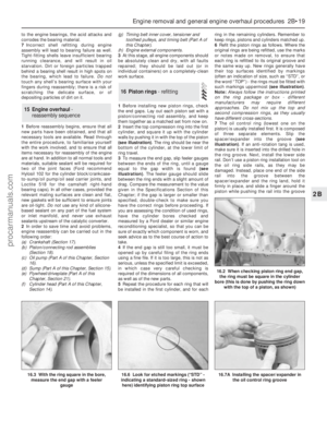 85
85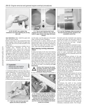 86
86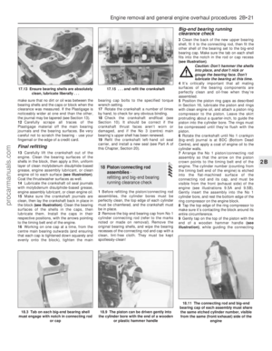 87
87 88
88 89
89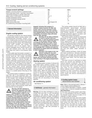 90
90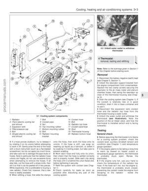 91
91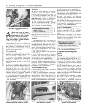 92
92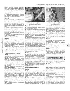 93
93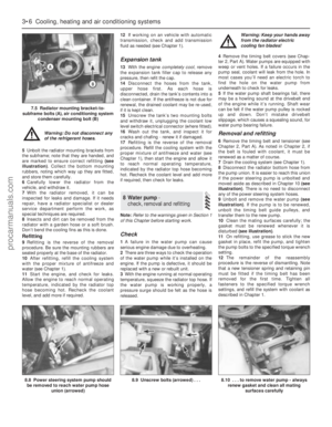 94
94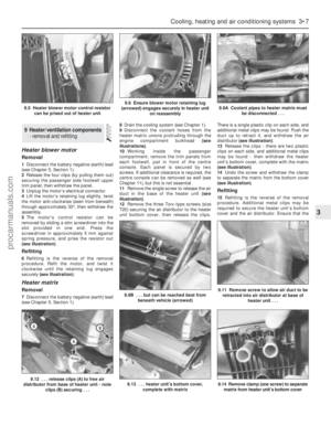 95
95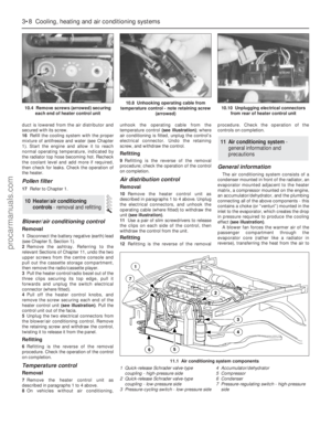 96
96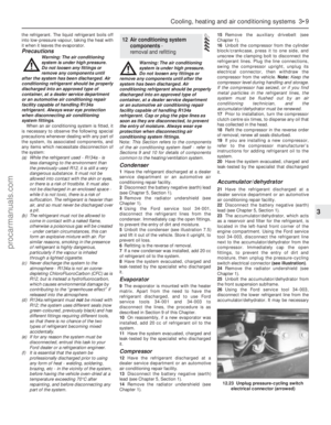 97
97 98
98 99
99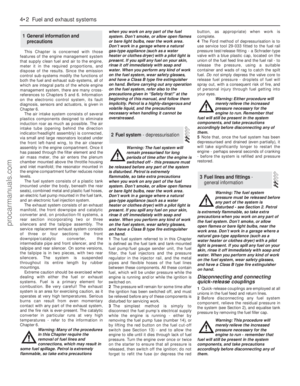 100
100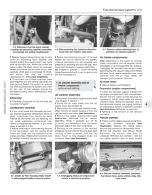 101
101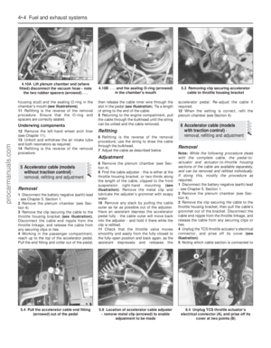 102
102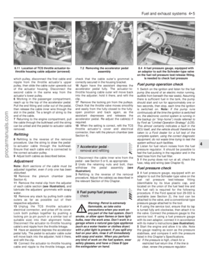 103
103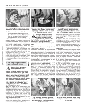 104
104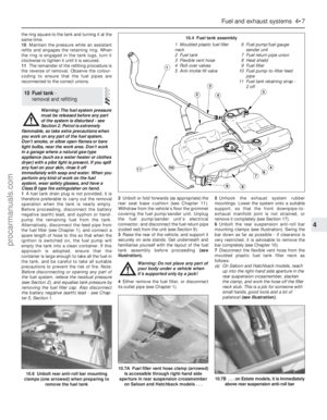 105
105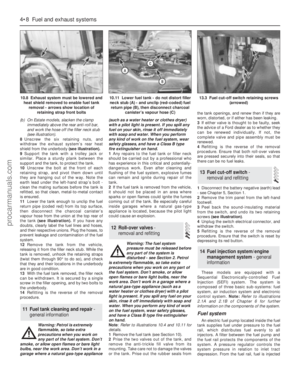 106
106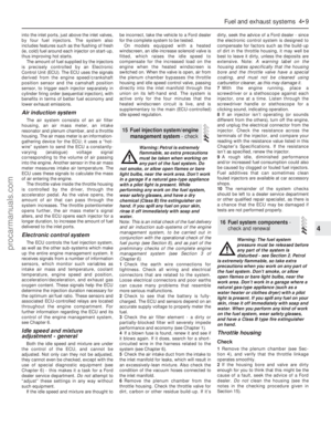 107
107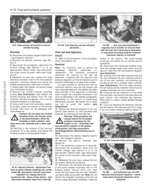 108
108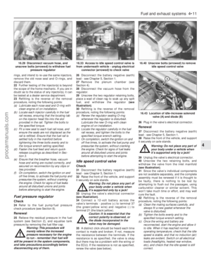 109
109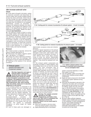 110
110 111
111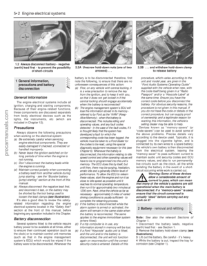 112
112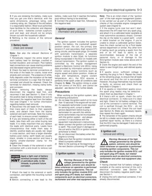 113
113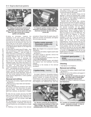 114
114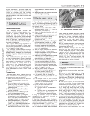 115
115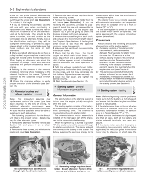 116
116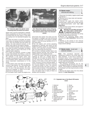 117
117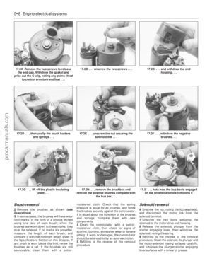 118
118 119
119 120
120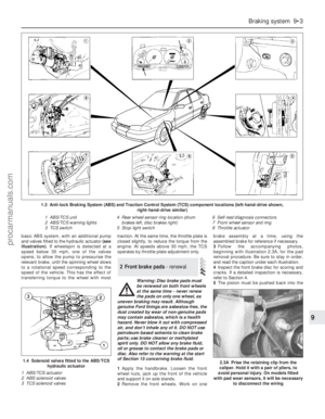 121
121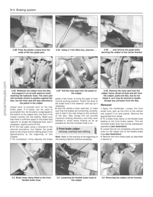 122
122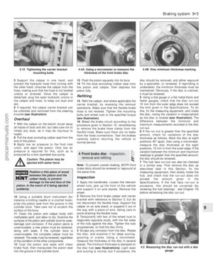 123
123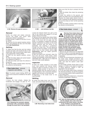 124
124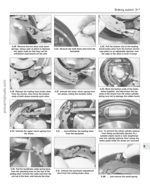 125
125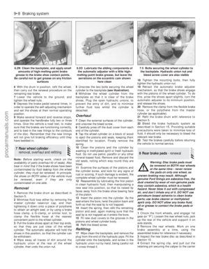 126
126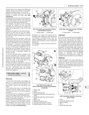 127
127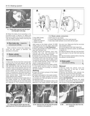 128
128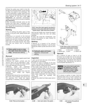 129
129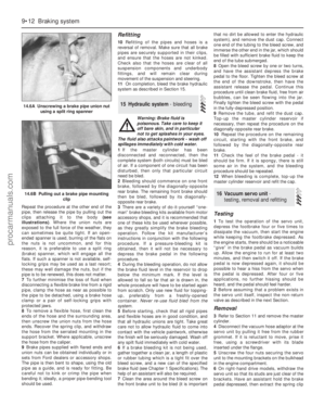 130
130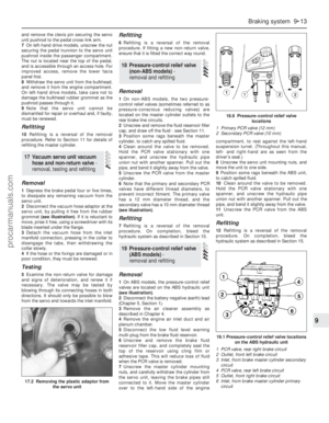 131
131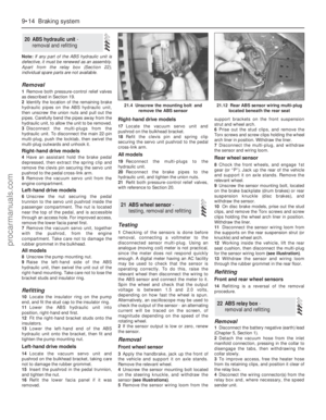 132
132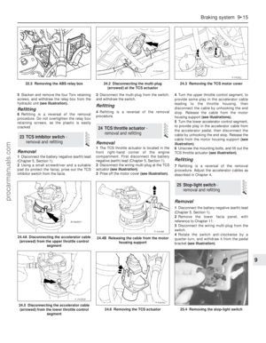 133
133 134
134 135
135 136
136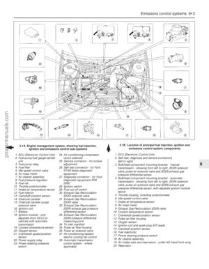 137
137 138
138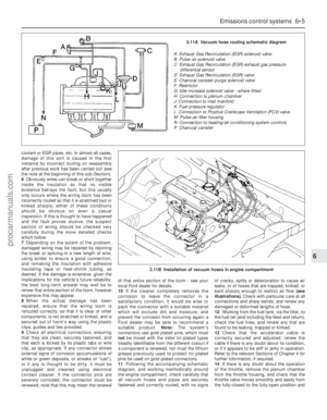 139
139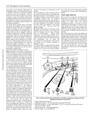 140
140 141
141 142
142 143
143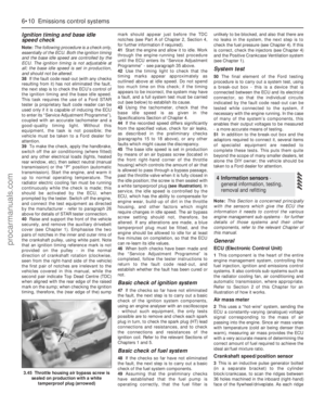 144
144 145
145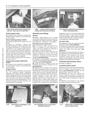 146
146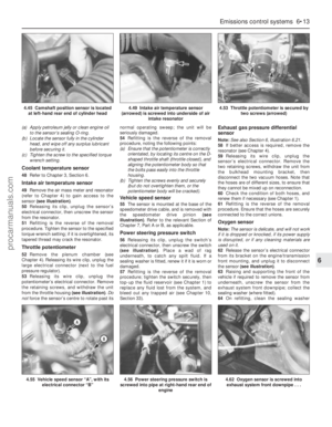 147
147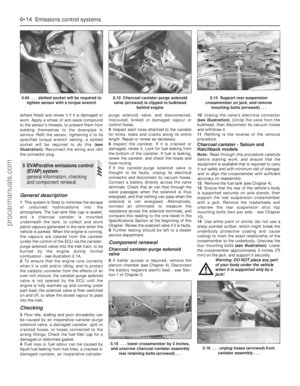 148
148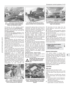 149
149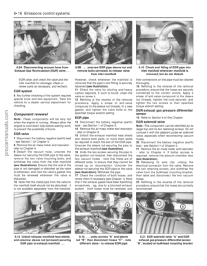 150
150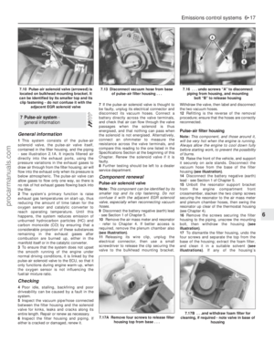 151
151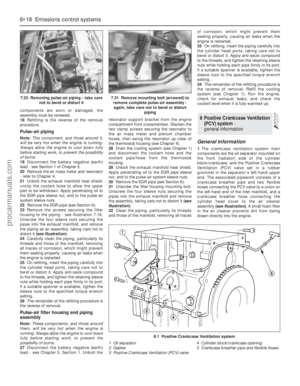 152
152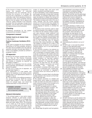 153
153 154
154 155
155 156
156 157
157 158
158 159
159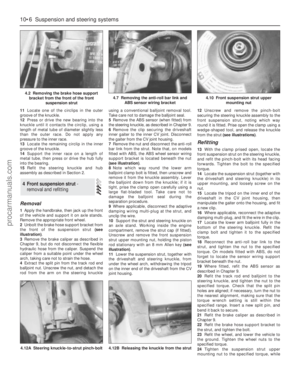 160
160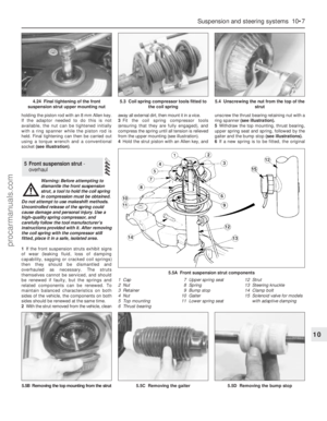 161
161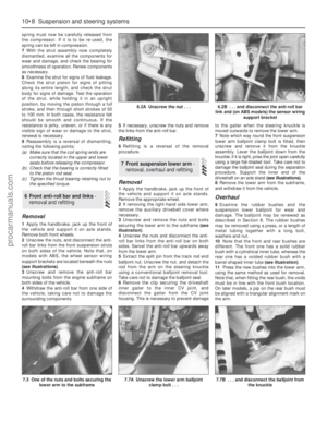 162
162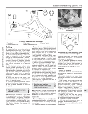 163
163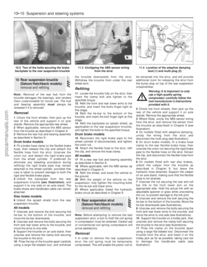 164
164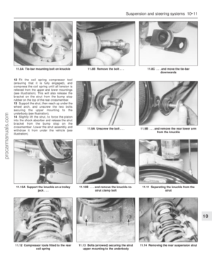 165
165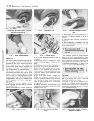 166
166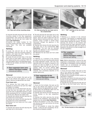 167
167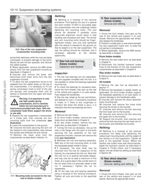 168
168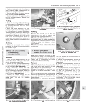 169
169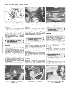 170
170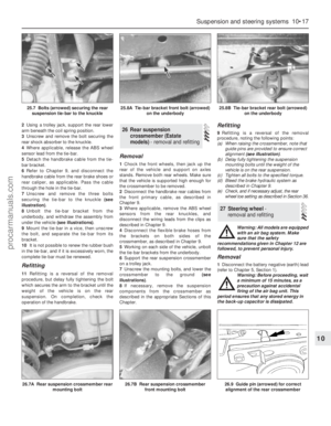 171
171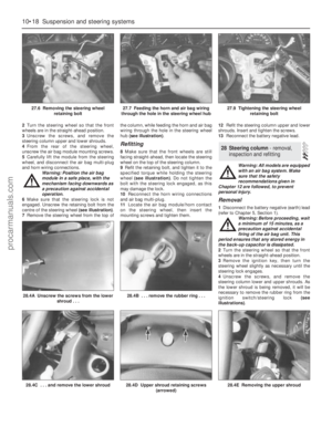 172
172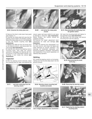 173
173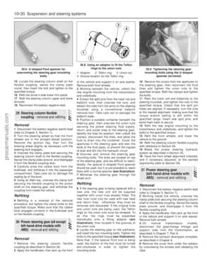 174
174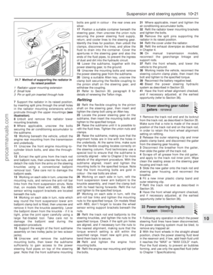 175
175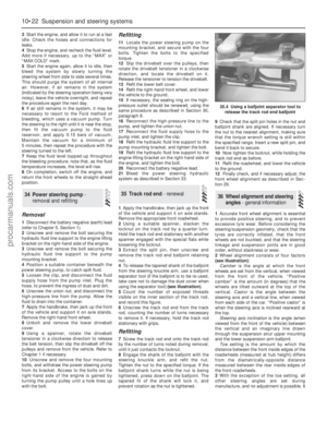 176
176 177
177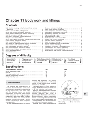 178
178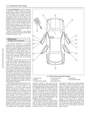 179
179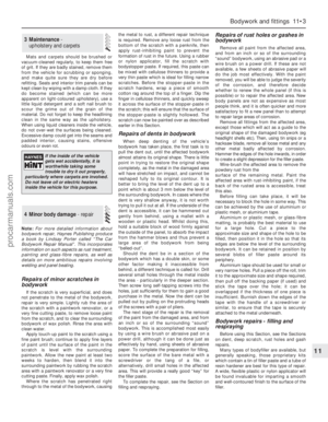 180
180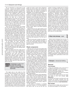 181
181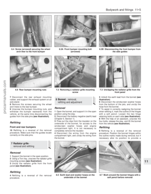 182
182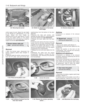 183
183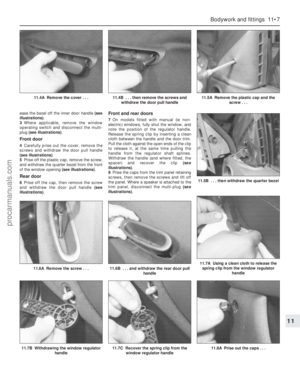 184
184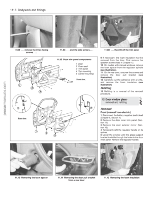 185
185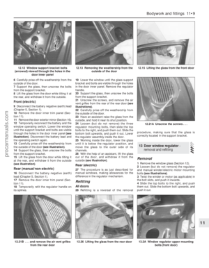 186
186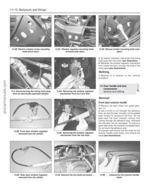 187
187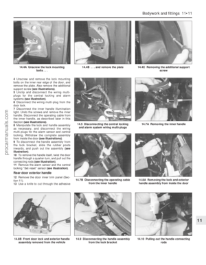 188
188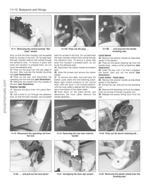 189
189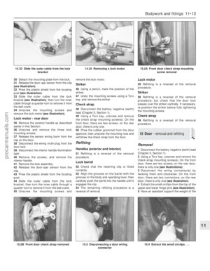 190
190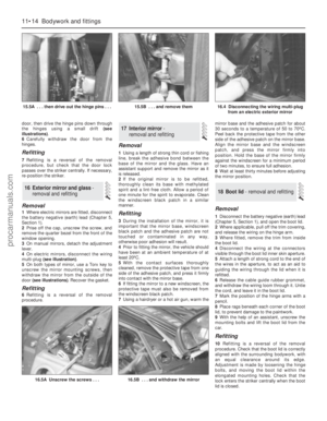 191
191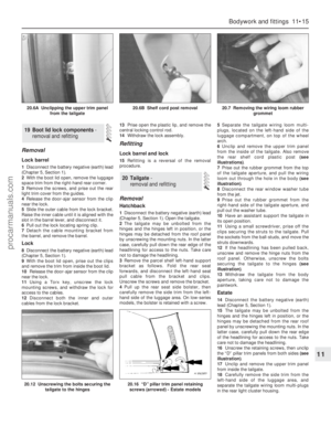 192
192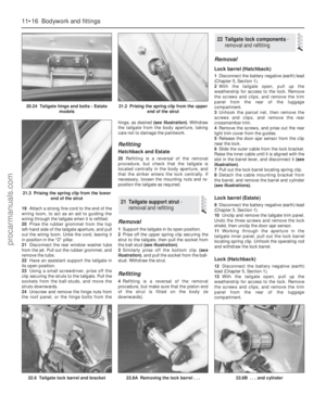 193
193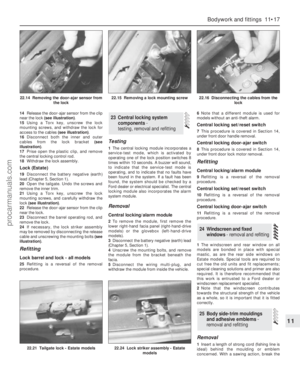 194
194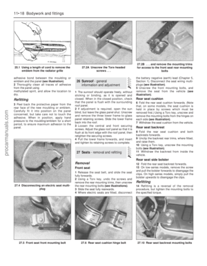 195
195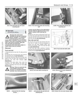 196
196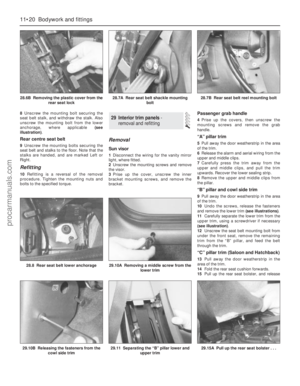 197
197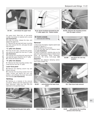 198
198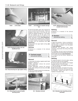 199
199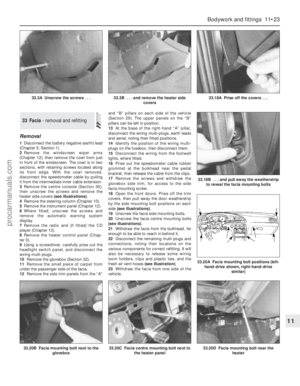 200
200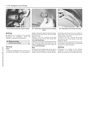 201
201 202
202 203
203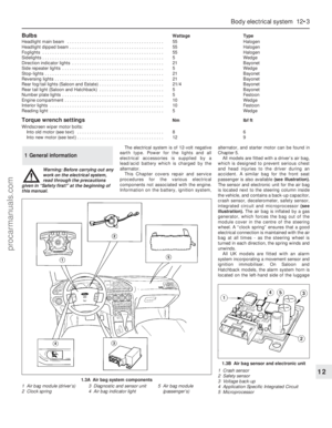 204
204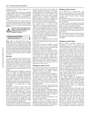 205
205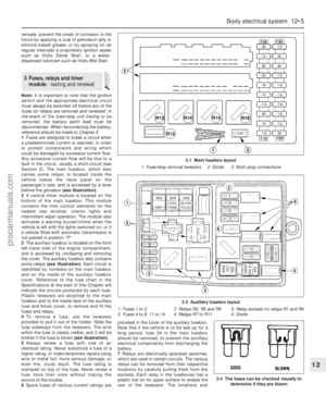 206
206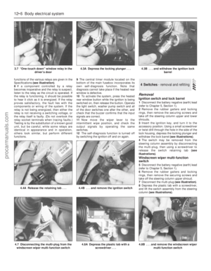 207
207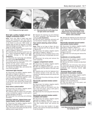 208
208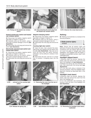 209
209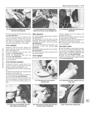 210
210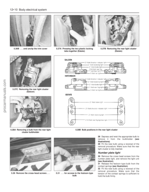 211
211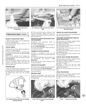 212
212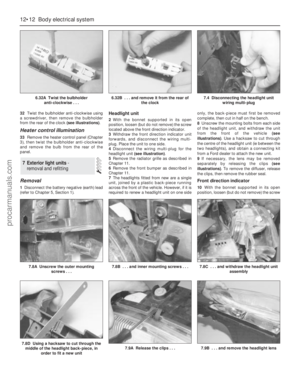 213
213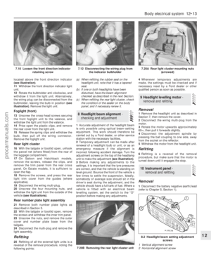 214
214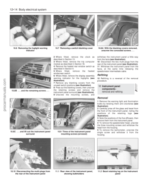 215
215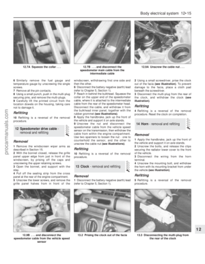 216
216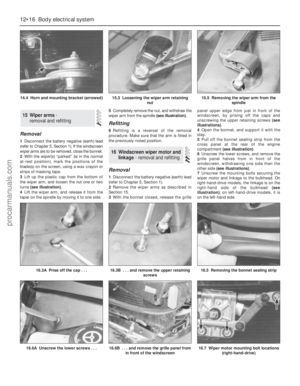 217
217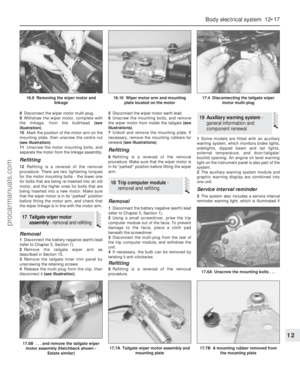 218
218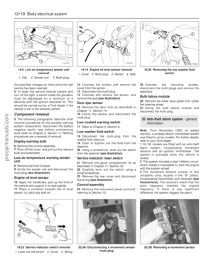 219
219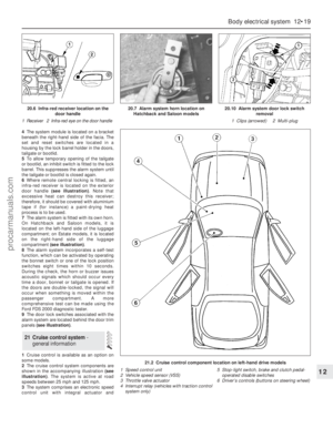 220
220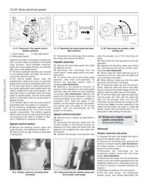 221
221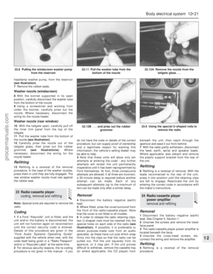 222
222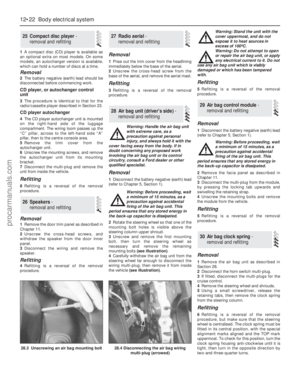 223
223 224
224 225
225 226
226 227
227 228
228 229
229 230
230 231
231 232
232 233
233 234
234 235
235 236
236 237
237 238
238 239
239 240
240 241
241 242
242 243
243 244
244 245
245 246
246 247
247 248
248 249
249 250
250 251
251 252
252 253
253 254
254 255
255 256
256 257
257 258
258 259
259 260
260 261
261 262
262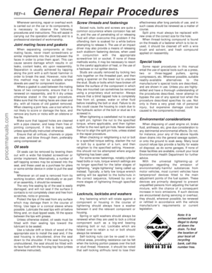 263
263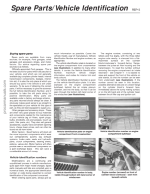 264
264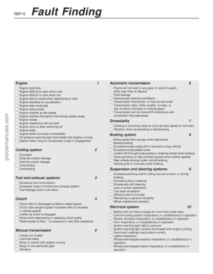 265
265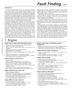 266
266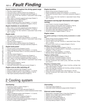 267
267 268
268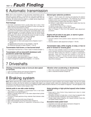 269
269 270
270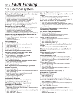 271
271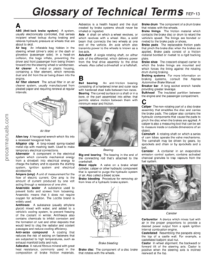 272
272 273
273 274
274 275
275 276
276 277
277 278
278