Page 217 of 279
 lead
(refer to Chapter 5, Section 1). If the windscreen
wiper arms are to be removed, close the bonnet.
2With the wiper(s) “parked” (ie in the norm")
Removal
1Disconnect the battery negative (earth) lead
(refer to Chapter 5, Section 1). If the windscreen
wiper arms are to be removed, close the bonnet.
2With the wiper(s) “parked” (ie in the normal
at-rest position), mark the positions of the
blade(s) on the screen, using a wax crayon or
strips of masking tape.
3Lift up the plastic cap from the bottom of
the wiper arm, and loosen the nut one or two
turns (see illustration).
4Lift the wiper arm, and release it from the
taper on the spindle by moving it to one side.5Completely remove the nut, and withdraw the
wiper arm from the spindle (see illustration).
Refitting
6Refitting is a reversal of the removal
procedure. Make sure that the arm is fitted in
the previously-noted position.
Removal
1Disconnect the battery negative (earth) lead
(refer to Chapter 5, Section 1).
2Remove the wiper arms as described in
Section 15.
3With the bonnet closed, release the grillepanel upper edge from just in front of the
windscreen, by prising off the caps and
unscrewing the upper retaining screws (see
illustrations).
4Open the bonnet, and support it with the
stay.
5Pull off the bonnet sealing strip from the
cross panel at the rear of the engine
compartment (see illustration).
6Unscrew the lower screws, and remove the
grille panel halves from in front of the
windscreen, withdrawing one side then the
other side (see illustrations).
7Unscrew the mounting bolts securing the
wiper motor and linkage to the bulkhead. On
right-hand-drive models, the linkage is on the
right-hand side of the bulkhead (see
illustration); on left-hand-drive models, it is
on the left-hand side.
16 Windscreen wiper motor and
linkage - removal and refitting
15 Wiper arms-
removal and refitting
12•16 Body electrical system
14.4 Horn and mounting bracket (arrowed)15.3 Loosening the wiper arm retaining
nut15.5 Removing the wiper arm from the
spindle
16.6A Unscrew the lower screws . . .16.6B . . . and remove the grille panel from
in front of the windscreen16.7 Wiper motor mounting bolt locations
(right-hand-drive)
16.3A Prise off the cap . . .16.3B . . . and remove the upper retaining
screws16.5 Removing the bonnet sealing strip
procarmanuals.com
Page 218 of 279
.
10Mark the position of the motor arm on the
mounting plate, then uns")
8Disconnect the wiper motor multi-plug.
9Withdraw the wiper motor, complete with
the linkage, from the bulkhead (see
illustration).
10Mark the position of the motor arm on the
mounting plate, then unscrew the centre nut
(see illustration).
11Unscrew the motor mounting bolts, and
separate the motor from the linkage assembly.
Refitting
12Refitting is a reversal of the removal
procedure. There are two tightening torques
for the motor mounting bolts - the lower one
for bolts that are being re-inserted into an old
motor, and the higher ones for bolts that are
being inserted into a new motor. Make sure
that the wiper motor is in its “parked” position
before fitting the motor arm, and check that
the wiper linkage is in line with the motor arm.
Removal
1Disconnect the battery negative (earth) lead
(refer to Chapter 5, Section 1).
2Remove the tailgate wiper arm as
described in Section 15.
3Remove the tailgate inner trim panel by
unscrewing the retaining screws.
4Release the multi-plug from the clip, then
disconnect it (see illustration).5Disconnect the wiper motor earth lead.
6Unscrew the mounting bolts, and remove
the wiper motor from inside the tailgate (see
illustrations).
7Unbolt and remove the mounting plate. If
necessary, remove the mounting rubbers for
renewal (see illustrations).
Refitting
8Refitting is a reversal of the removal
procedure. Make sure that the wiper motor is
in its “parked” position before fitting the wiper
arm.
Removal
1Disconnect the battery negative (earth) lead
(refer to Chapter 5, Section 1).
2Using a small screwdriver, prise the trip
computer module out of the facia. To prevent
damage to the facia, place a cloth pad
beneath the screwdriver.
3Disconnect the multi-plug from the rear of
the trip computer module, and withdraw the
unit.
4If necessary, the bulb can be removed by
twisting it anti-clockwise.
Refitting
5Refitting is a reversal of the removal
procedure.1Some models are fitted with an auxiliary
warning system, which monitors brake lights,
sidelights, dipped beam and tail lights,
external temperature, and door/tailgate/
bootlid opening. An engine oil level warning
light on the instrument panel is also part of the
system.
2The auxiliary warning system module and
graphic warning display are combined into
one unit.
Service interval reminder
3The system also includes a service interval
reminder warning light, which is illuminated if
19 Auxiliary warning system -
general information and
component renewal
18 Trip computer module-
removal and refitting
17 Tailgate wiper motor
assembly - removal and refitting
Body electrical system 12•17
12
17.6B . . . and remove the tailgate wiper
motor assembly (Hatchback shown -
Estate similar)17.7A Tailgate wiper motor assembly and
mounting plate17.7B A mounting rubber removed from
the mounting plate
17.6A Unscrew the mounting bolts . . .
16.9 Removing the wiper motor and
linkage16.10 Wiper motor arm and mounting
plate located on the motor17.4 Disconnecting the tailgate wiper
motor multi-plug
procarmanuals.com
Page 219 of 279
 since the last
service has been reached.
4To reset the service interval system and
turn off the light, a switch inside the glovebox
must be depressed for a minimum of 4")
the specified mileage (or time) since the last
service has been reached.
4To reset the service interval system and
turn off the light, a switch inside the glovebox
must be depressed for a minimum of 4
seconds with the ignition switched on. This
should be carried out by a Ford dealer if the
vehicle is still in the warranty period.
Component renewal
5The following paragraphs describe brief
removal procedures for the auxiliary warning
system components. Disconnect the battery
negative (earth) lead before commencing
work (refer to Chapter 5, Section 1). Refitting
procedures are a reversal of removal.
Display warning bulb
6Remove the control assembly.
7Prise off the cover, and pull out the relevant
bulb and bulbholder.
Low air temperature warning sender
unit
8Remove the front bumper.
9Unclip the sender unit and disconnect the
multi-plug (see illustration).
Engine oil level sensor
10Apply the handbrake, jack up the front of
the vehicle and support it on axle stands.
11Place a container beneath the oil level
sensor, to catch any spilt oil.12Unscrew the screws and remove the
cover from the sensor.
13Disconnect the multi-plug.
14Unscrew and remove the sensor, and
remove the seal (see illustration).
Door ajar sensor
15Remove the door lock as described in
Chapter 11, Section 14.
16Unclip the sensor and disconnect the
multi-plug.
Low coolant warning switch
17Refer to Chapter 3, Section 6.
Low washer fluid switch
18Disconnect the multi-plug from the
washer fluid reservoir.
19Drain or syphon out the fluid from the
reservoir.
20Using a screwdriver, lever out the switch
from the reservoir (see illustration).
Service indicator reset switch
21Remove the glove compartment lid as
described in Chapter 11, Section 32.
22Carefully lever out the switch using a
small screwdriver.
23Remove the rear cover and disconnect
the wiring (see illustration).
Control assembly
24Remove the instrument panel surround,
referring to Section 10.25Unscrew the mounting screws,
disconnect the multi-plugs and remove the
assembly.
Bulb failure module
26Remove the lower facia panel from under
the steering wheel.
27Unclip the bulb failure module and
disconnect the multi-plug.
Note: From November 1993, for added
security, a complex Bosch immobiliser system
was fitted to some models. For further details,
refer to your Ford dealer.
1All UK models are fitted with an anti-theft
alarm system, incorporating movement
sensors and an ignition immobiliser. The
system is activated when the vehicle is
locked.
2The system includes a start inhibitor circuit,
which makes it impossible to start the engine
with the system armed.
3The movement sensors consist of two
ultrasonic units, located in the “B” pillars,
incorporating transmitters and receivers (see
illustrations). The receivers check that the
echo frequency matches the original
frequency. If there is any significant
difference, the system triggers the alarm.
20 Anti-theft alarm system- general
information
12•18 Body electrical system
19.9 Low air temperature sender unit
removal
1 Clip 2 Sender unit 3 Multi-plug19.14 Engine oil level sensor removal
1 Cover 2 Multi-plug 3 Sensor 4 Seal19.20 Removing the low washer fluid
switch
19.23 Service indicator switch removal
1 Lever out the switch 2 Cover 3 Wiring20.3A Disconnecting a movement sensor
multi-plug20.3B Removing a movement sensor
procarmanuals.com
Page 220 of 279

4The system module is located on a bracket
beneath the right-hand side of the facia. The
set and reset switches are located in a
housing by the lock barrel holder in the doors,
tailgate or bootlid.
5To allow temporary opening of the tailgate
or bootlid, an inhibit switch is fitted to the lock
barrel. This suppresses the alarm system until
the tailgate or bootlid is closed again.
6Where remote central locking is fitted, an
infra-red receiver is located on the exterior
door handle (see illustration). Note that
excessive heat can destroy this receiver;
therefore, it should be covered with aluminium
tape if (for instance) a paint-drying heat
process is to be used.
7The alarm system is fitted with its own horn.
On Hatchback and Saloon models, it is
located on the left-hand side of the luggage
compartment; on Estate models, it is located
on the right-hand side of the luggage
compartment (see illustration).
8The alarm system incorporates a self-test
function, which can be activated by operating
the bonnet switch or one of the lock position
switches eight times within 10 seconds.
During the check, the horn or buzzer issues
acoustic signals which should occur every
time a door, bonnet or tailgate is opened. If
the doors are double-locked, the signal will
occur when something is moved within the
passenger compartment. A more
comprehensive test can be made using the
Ford FDS 2000 diagnostic tester.
9The door lock switches associated with the
alarm system are located behind the door trim
panels (see illustration).
1Cruise control is available as an option on
some models.
2The cruise control system components are
shown in the accompanying illustration (see
illustration). The system is active at road
speeds between 25 mph and 125 mph.
3The system comprises an electronic speed
control unit with integral actuator and
21 Cruise control system -
general information
Body electrical system 12•19
12
21.2 Cruise control component location on left-hand drive models
1 Speed control unit
2 Vehicle speed sensor (VSS)
3 Throttle valve actuator
4 Interrupt relay (vehicles with traction control
system only)5 Stop-light switch, brake and clutch pedal-
operated disable switches
6 Driver’s controls (buttons on steering wheel)
20.6 Infra-red receiver location on the
door handle
1 Receiver 2 Infra-red eye on the door handle20.7 Alarm system horn location on
Hatchback and Saloon models20.10 Alarm system door lock switch
removal
1 Clips (arrowed) 2 Multi-plug
procarmanuals.com
Page 221 of 279

switches mounted in the engine compartment
with a control cable connected to the throttle
valve actuator, driver-operated switches,
brake and clutch pedal switches, an indicator
light, and a road speed sensor.
4The driver-operated switches are mounted
on the steering wheel, and allow the driver to
control the various functions.
5The vehicle speed sensor uses the
speedometer cable drive pinion to generate
pulses which are fed to the speed control unit.
6The stop-light switch, brake pedal switch
and (when applicable) clutch pedal switch are
used to disable the cruise control system. The
stop-light switch is activated when the brake
pedal is applied gently, and the brake pedal
switch is activated when the brake pedal is
applied forcibly.
7An indicator light on the instrument panel is
illuminated when the system is in operation.
8The following paragraphs describe brief
removal procedures for the cruise control
system components. The battery negative
(earth) lead should be disconnected before
commencing work (refer to Chapter 5, Sec-
tion 1). Refitting is a reversal of removal.
Speed control switch
9Remove the steering column upper and
lower shrouds, with reference to Chapter 10.
10Remove the air bag module as described
in Section 29.11Disconnect the multi-plugs, then unscrew
the screws and remove the switch.
Disable switches
12Remove the lower facia panel from under
the steering column.
13Disconnect the multi-plugs from the
clutch switch, brake pedal switch and stop-
light switch.
14To remove the clutch and brake pedal
switches, twist them anti-clockwise. To
remove the stop-light switch, twist it
clockwise (see illustration).
15Refitting is the reverse of removal. To
ensure correct operation of the brake pedal
switches, reset the switch by fully extending
its plunger (see illustration).Depress the
pedal until the distance between it and the
mounting bracket is as shown in Chapter 9,
illustration 25.6. Hold the pedal in this
position, clip the switch securely into position
and gently raise the pedal to the at-rest
position. This will automatically set the
position of the switch.
Speed control actuator
16Remove the air cleaner as described in
Chapter 4.
17Disconnect the actuator cable from the
throttle linkage on the throttle housing, by
releasing the inner cable end fitting from the
segment and unclipping the outer cable from
the bracket.
18Unscrew the actuator mounting bolt, thenslide the actuator out of the mounting pin
holes.
19Disconnect the multi-plug and remove the
assembly.
20Depress the actuating cable cap locking
arm, and remove the cap by turning it anti-
clockwise (see illustration).
21Gently raise the cable retaining lug by a
maximum of 0.5 mm, and push the cable end
out of the slot in the pulley.
22When refitting, make sure that the cable
end locks into the slot in the pulley.
23To locate the cable cap onto the actuator
pulley, keep the cable taut and in the pulley
groove, and pull the throttle linkage end of the
cable to draw the cable cap onto the pulley.
24To refit the cable cap, keep the cable taut
and the pulley still, then refit the cable cap
tabs into the actuator slots; turn the cap
clockwise until the locking arm locates on the
locking stop. Note:Incorrect assembly of the
cable onto the pulley may result in a high idle
speed. Check that the throttle lever is in its
idle position after refitting the actuator.
Removal
Washer reservoir and pump
1Unscrew the bolts, and release the clips to
remove the radiator lower cover.
2Unscrew the mounting bolts, and pull the
reservoir forwards slightly (see illustration).
For better access, it may be necessary to
remove the front bumper.
3Disconnect the multi-plugs for the
windscreen washer pump and fluid level
sensor (see illustration).
4Disconnect the hoses from the windscreen
washer pump and (where applicable) from the
headlamp washer pump. Anticipate some loss
of fluid by placing a container beneath the
reservoir.
5Withdraw the reservoir from the vehicle.
6Pull the level sensor, the windscreen
washer pump, and (where applicable) the
22 Windscreen/tailgate washer
system components -
removal and refitting
12•20 Body electrical system
21.14 Removal of the speed control
disable switches
1 Clutch switch 3 Stop-light switch
2 Brake pedal switch21.15 Resetting the brake pedal and stop-
light switches21.20 Removing the actuator cable
locking arm
22.2 Washer reservoir mounting bolts
(arrowed)22.3 Disconnecting the washer pump and
level sensor multi-plugs
procarmanuals.com
Page 222 of 279
.
7Remove the rubber seals.
Washer nozzle (windscreen)
8With the bonnet supported in its open
position, carefully disconnect the washer tube")
headlamp washer pump, from the reservoir
(see illustration).
7Remove the rubber seals.
Washer nozzle (windscreen)
8With the bonnet supported in its open
position, carefully disconnect the washer tube
from the bottom of the nozzle.
9Using a screwdriver and working from
under the bonnet, carefully prise out the
nozzle. Where necessary, disconnect the
wiring for the nozzle heater.
Washer nozzle (rear window)
10With the tailgate open, carefully pull off
the inner trim panel from the top of the
tailgate.
11Pull the washer tube from the bottom of
the nozzle (see illustration).
12Carefully prise the nozzle out of the
tailgate glass, then prise out the rubber
grommet (see illustrations). Where
necessary, disconnect the wiring for the
nozzle heater.
Refitting
13Refitting is a reversal of the removal
procedure. In the case of the washer nozzles,
press them in until they are fully engaged. The
rear window washer nozzle must rest against
the rubber seal.
Note:Special tools are required to remove the
radio.
Coding
1If a Ford “Keycode” unit is fitted, and the
unit and/or the battery is disconnected, the
unit will not function again on reconnection
until the correct security code is entered.
Details of this procedure are given in the
“Ford Audio Systems Operating Guide”
supplied with the vehicle when new, with the
code itself being given in a “Radio Passport”
and/or a “Keycode Label” at the same time.
2For obvious security reasons, the re-coding
procedure is not given in this manual - if youdo not have the code or details of the correct
procedure, but can supply proof of ownership
and a legitimate reason for wanting this
information, the vehicle’s selling dealer may
be able to help.
3Note that these units will allow only ten
attempts at entering the code - any further
attempts will render the unit permanently
inoperative until it has been reprogrammed by
Ford themselves. At first, three consecutive
attempts are allowed; if all three are incorrect,
a 30-minute delay is required before another
attempt can be made. Each of any
subsequent attempts (up to the maximum of
ten) can be made only after a similar delay.
Removal
4Disconnect the battery negative (earth)
lead.
5Where fitted, prise the cover/surround from
the front of the radio/cassette player. Note
that the cover is not fitted to all models.
6In order to release the radio retaining clips,
two U-shaped rods must be inserted into the
special holes on each side of the radio (see
illustration). If possible, it is preferable to
obtain purpose-made rods from an audio
specialist, as these have cut-outs which snap
firmly into the clips so that the radio can be
pulled out. Pull the unit squarely from its
aperture, or it may jam. If the unit proves
difficult to withdraw, remove the cassette tray
(or where applicable, the CD player) frombeneath the unit, then reach through the
aperture and ease it out from behind.
7With the radio partly withdrawn, disconnect
the feed, earth, aerial and speaker leads.
Where applicable, also detach and remove
the plastic support bracket from the rear of
the unit.
Refitting
6Refitting is a reversal of removal. With the
leads reconnected to the rear of the unit,
press it into position until the retaining clips
are felt to engage. Reactivate the unit by
entering the correct code in accordance with
the maker’s instructions.
Removal
1Disconnect the battery negative (earth)
lead. See Chapter 5, Section 1.
2Unscrew the screws and remove the lower
facia panel.
3The radio/cassette player power amplifier is
located beneath the facia.
4Unscrew the cross-head screws, dis-
connect the wiring and remove the amplifier.
Refitting
5Refitting is a reversal of the removal
procedure.
24 Radio/cassette player
power amplifier -
removal and refitting
23 Radio/cassette player -
coding, removal and refitting
Body electrical system 12•21
12
22.12B . . . and prise out the rubber
grommet23.6 Using the special U-shaped rods to
remove the radio
22.6 Pulling the windscreen washer pump
from the reservoir22.11 Pull the washer tube from the
bottom of the nozzle22.12A Remove the nozzle from the
tailgate glass . . .
procarmanuals.com
Page 223 of 279
 player is available as
an optional extra on most models. On some
models, an autochanger version is available,
which can hold a number of discs at a time.
Removal
2The battery nega")
1A compact disc (CD) player is available as
an optional extra on most models. On some
models, an autochanger version is available,
which can hold a number of discs at a time.
Removal
2The battery negative (earth) lead should be
disconnected before commencing work.
CD player, or autochanger control
unit
3The procedure is identical to that for the
radio/cassette player described in Section 23.
CD player autochanger
4The CD player autochanger unit is mounted
on the right-hand side of the luggage
compartment. The wiring loom passes up the
“C” pillar, across to the left-hand side “A”
pillar, then to the centre console area.
5Remove the trim cover from the
autochanger unit.
6Unscrew the mounting screws, and remove
the autochanger unit from its mounting
bracket.
7Disconnect the multi-plug and remove the
unit from inside the vehicle.
Refitting
8Refitting is a reversal of the removal
procedure.
Removal
1Remove the door trim panel as described in
Chapter 11.
2Unscrew the cross-head screws, and
withdraw the speaker from the door inner
panel.
3Disconnect the wiring and remove the
speaker.
Refitting
4Refitting is a reversal of the removal
procedure.
Removal
1Prise out the trim cover from the headlining
immediately below the base of the aerial.
2Unscrew the cross-head screw from the
base of the aerial, and remove the aerial mast.
Refitting
3Refitting is a reversal of the removal
procedure.
Warning: Handle the air bag unit
with extreme care, as a
precaution against personal
injury, and always hold it with the
cover facing away from the body. If in
doubt concerning any proposed work
involving the air bag unit or its control
circuitry, consult a Ford dealer or other
qualified specialist.
Removal
1Disconnect the battery negative (earth) lead
(refer to Chapter 5, Section 1).
Warning: Before proceeding, wait
a minimum of 15 minutes, as a
precaution against accidental
firing of the air bag unit. This
period ensures that any stored energy in
the back-up capacitor is dissipated.
2Rotate the steering wheel so that one of the
mounting bolt holes is visible above the
steering column upper shroud.
3Unscrew and remove the first mounting
bolt, then turn the steering wheel as
necessary and remove the remaining
mounting bolts (see illustration).
4Carefully withdraw the air bag unit from the
steering wheel far enough to disconnect the
wiring multi-plug, then remove it from inside
the vehicle (see illustration). Warning: Stand the unit with the
cover uppermost, and do not
expose it to heat sources in
excess of 100ºC.
Warning: Do not attempt to open
or repair the air bag unit, or apply
any electrical current to it. Do not
use any air bag unit which is visibly
damaged or which has been tampered
with.
Refitting
5Refitting is a reversal of the removal
procedure.
Removal
1Disconnect the battery negative (earth) lead
(refer to Chapter 5, Section 1).
Warning: Before proceeding, wait
a minimum of 15 minutes, as a
precaution against accidental
firing of the air bag unit. This
period ensures that any stored energy in
the back-up capacitor is dissipated.
2Remove the facia panel as described in
Chapter 11.
3Disconnect the multi-plug from the module,
by pressing the locking tab upwards and
swivelling the retaining strap.
4Unscrew the mounting bolts and remove
the module from the vehicle.
Refitting
5Refitting is a reversal of the removal
procedure.
Removal
1Remove the air bag unit as described in
Section 28.
2Disconnect the horn switch multi-plug.
3If fitted, disconnect the multi-plugs for the
cruise control.
4Remove the steering wheel and shrouds.
5Using a small screwdriver, release the
retaining tabs, then remove the clock spring
from the steering column.
Refitting
6Refitting is a reversal of the removal
procedure, but make sure that the steering
wheel is centralised. The clock spring must be
fitted in its central position, with the special
alignment marks aligned and the TOP mark
uppermost. To check for this position, turn the
clock spring housing anti-clockwise until it is
tight, then turn in the opposite direction by
two-and-three-quarter turns.
30 Air bag clock spring-
removal and refitting
29 Air bag control module -
removal and refitting
28 Air bag unit (driver’s side) -
removal and refitting
27 Radio aerial -
removal and refitting
26 Speakers -
removal and refitting
25 Compact disc player -
removal and refitting
12•22 Body electrical system
28.3 Unscrewing an air bag mounting bolt28.4 Disconnecting the air bag wiring
multi-plug (arrowed)
procarmanuals.com
Page 224 of 279
Wiring diagrams 12•23
12
Notes, internal connection details and key to symbols
procarmanuals.com
 1
1 2
2 3
3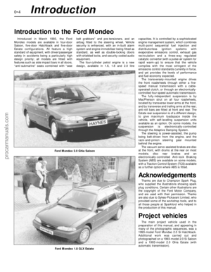 4
4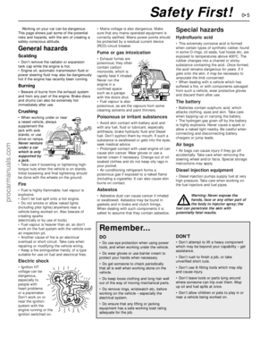 5
5 6
6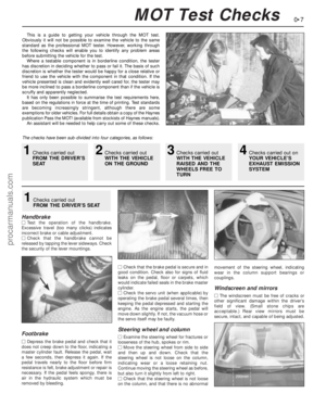 7
7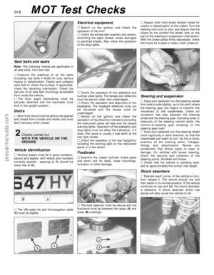 8
8 9
9 10
10 11
11 12
12 13
13 14
14 15
15 16
16 17
17 18
18 19
19 20
20 21
21 22
22 23
23 24
24 25
25 26
26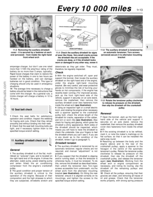 27
27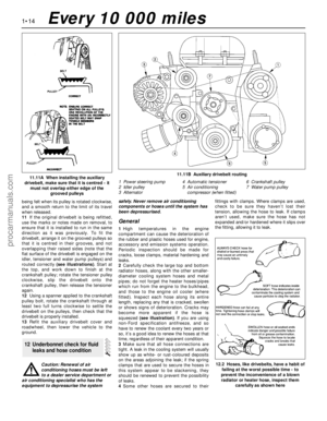 28
28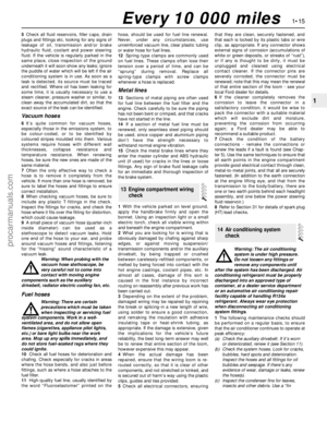 29
29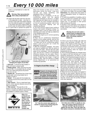 30
30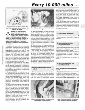 31
31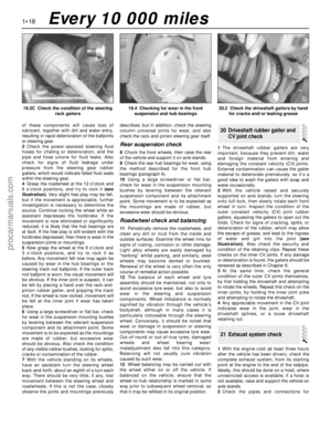 32
32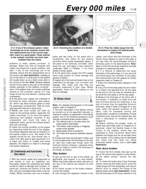 33
33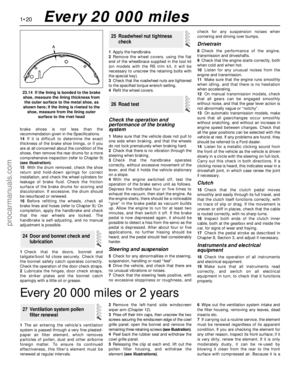 34
34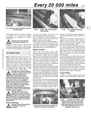 35
35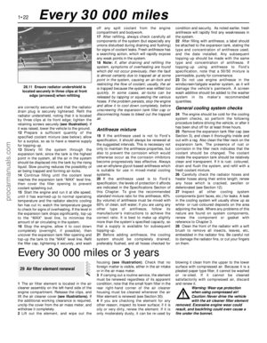 36
36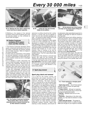 37
37 38
38 39
39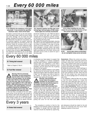 40
40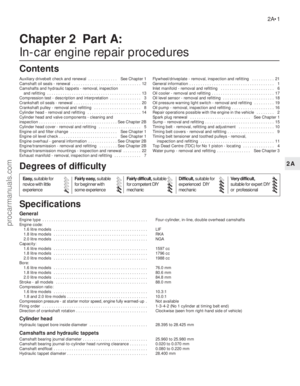 41
41 42
42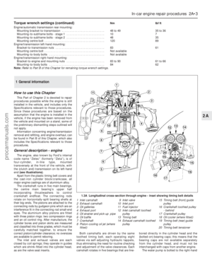 43
43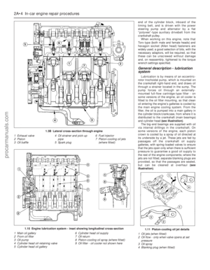 44
44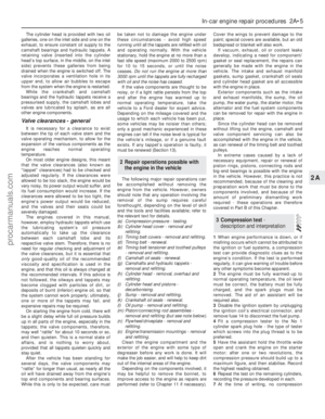 45
45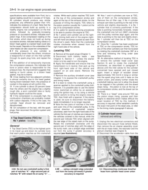 46
46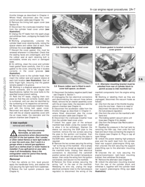 47
47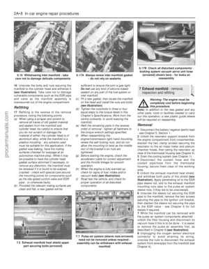 48
48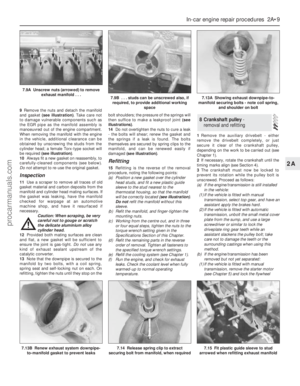 49
49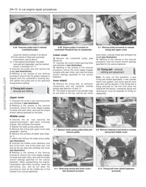 50
50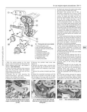 51
51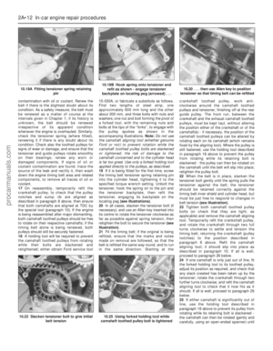 52
52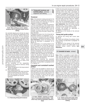 53
53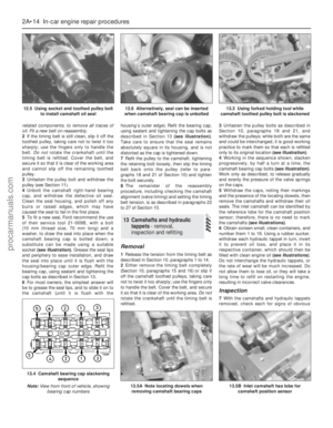 54
54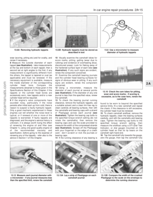 55
55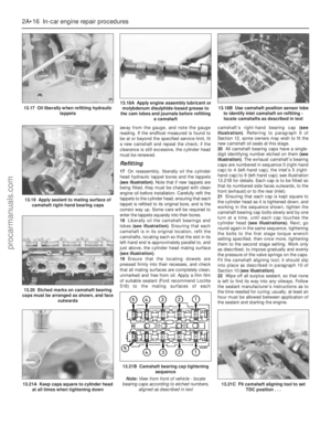 56
56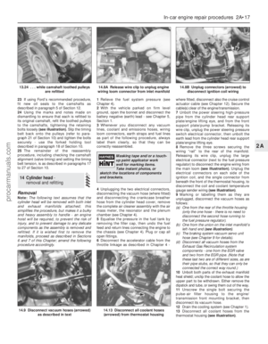 57
57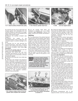 58
58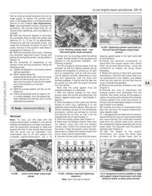 59
59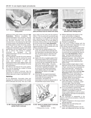 60
60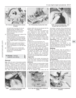 61
61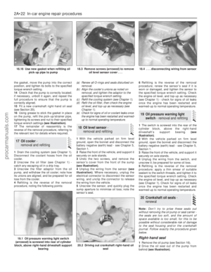 62
62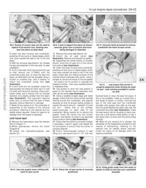 63
63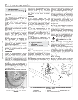 64
64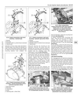 65
65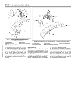 66
66 67
67 68
68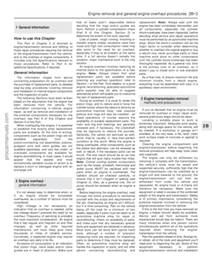 69
69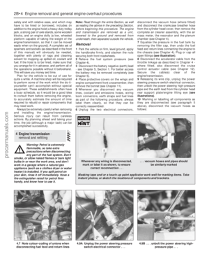 70
70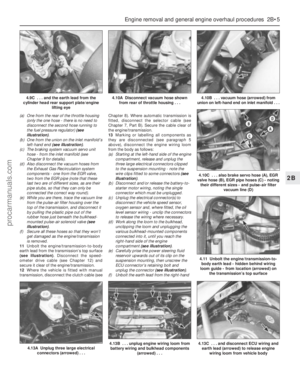 71
71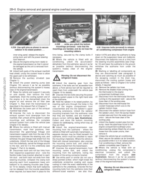 72
72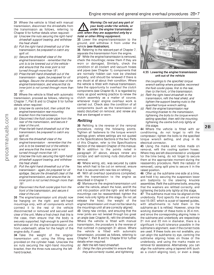 73
73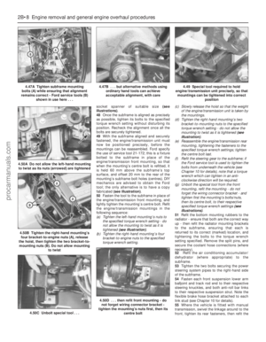 74
74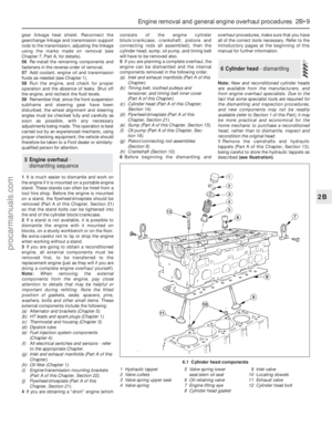 75
75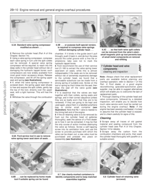 76
76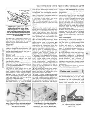 77
77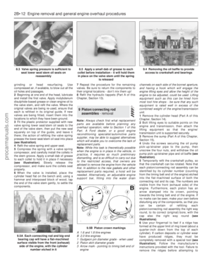 78
78 79
79 80
80 81
81 82
82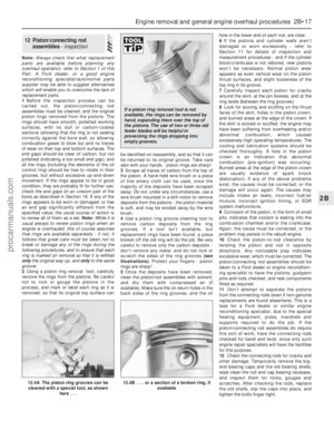 83
83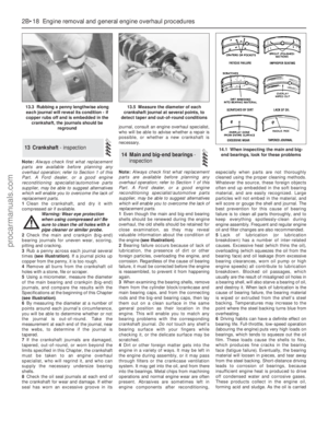 84
84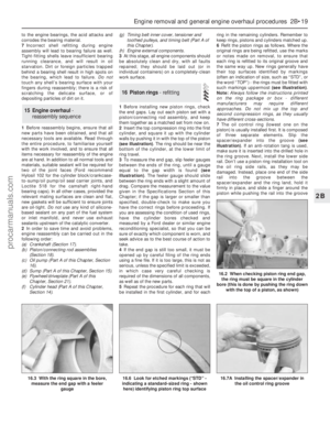 85
85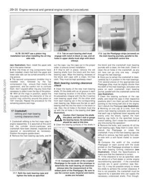 86
86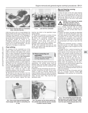 87
87 88
88 89
89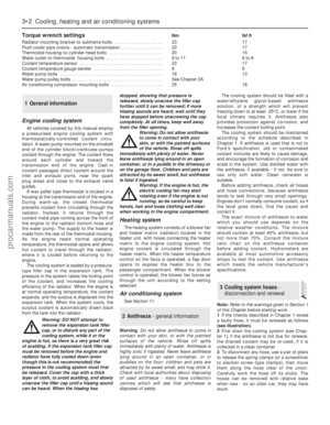 90
90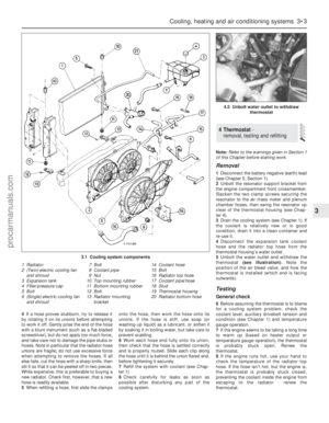 91
91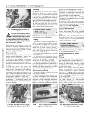 92
92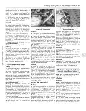 93
93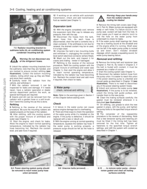 94
94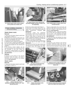 95
95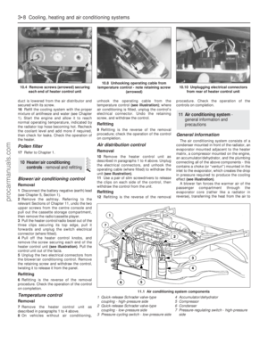 96
96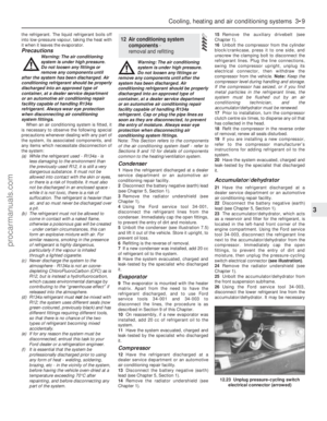 97
97 98
98 99
99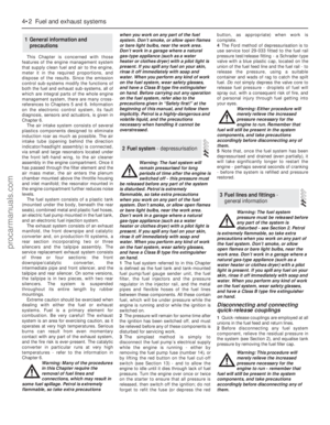 100
100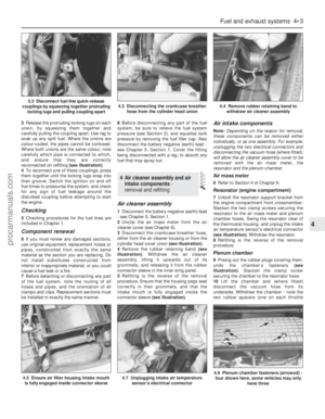 101
101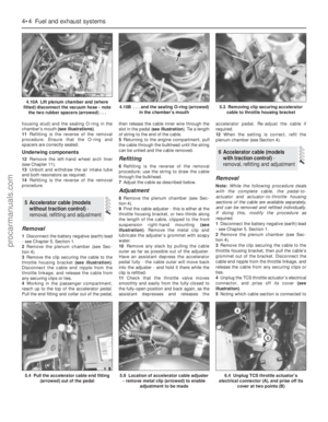 102
102 103
103 104
104 105
105 106
106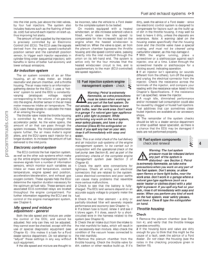 107
107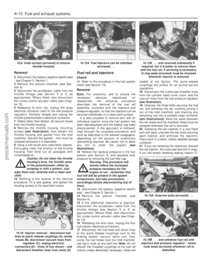 108
108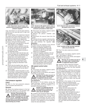 109
109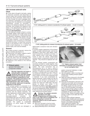 110
110 111
111 112
112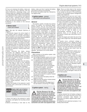 113
113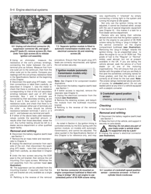 114
114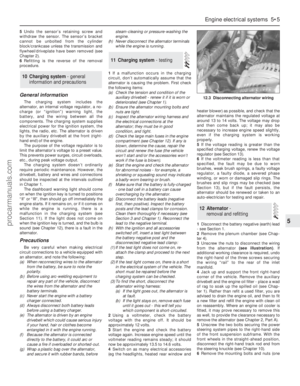 115
115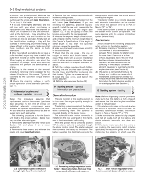 116
116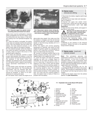 117
117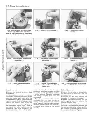 118
118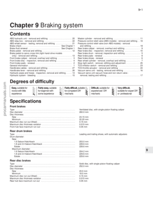 119
119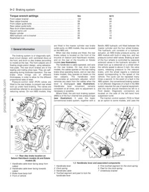 120
120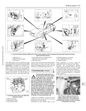 121
121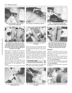 122
122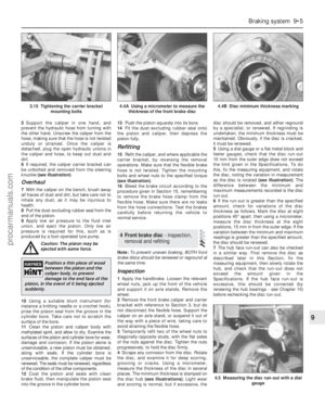 123
123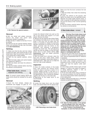 124
124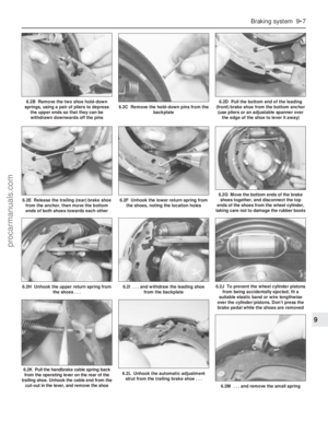 125
125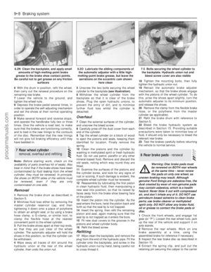 126
126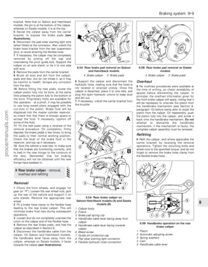 127
127 128
128 129
129 130
130 131
131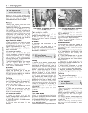 132
132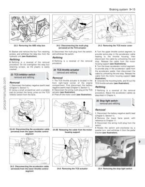 133
133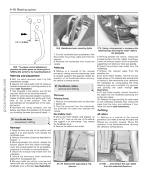 134
134 135
135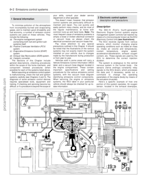 136
136 137
137 138
138 139
139 140
140 141
141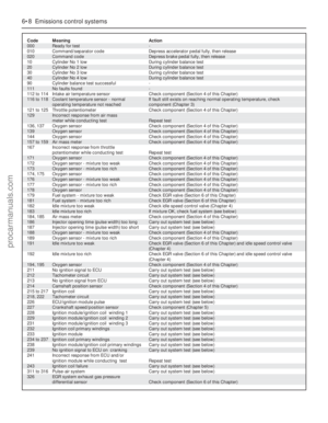 142
142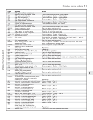 143
143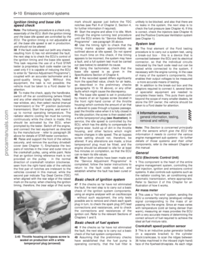 144
144 145
145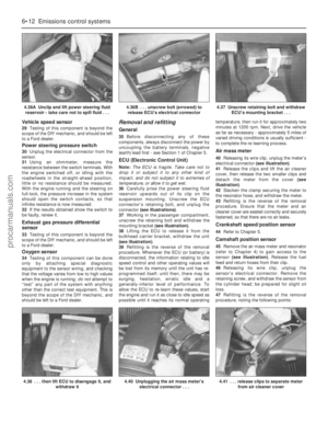 146
146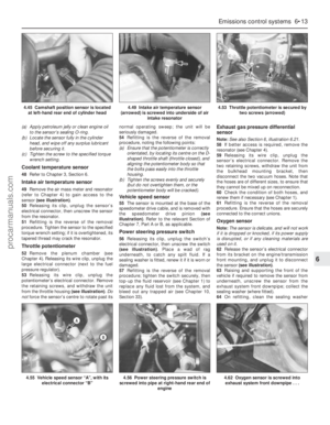 147
147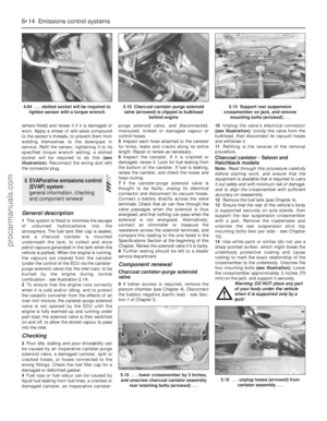 148
148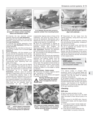 149
149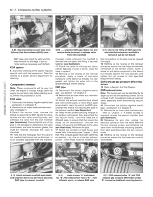 150
150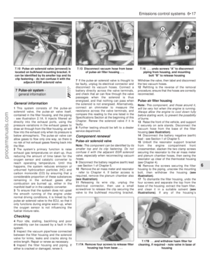 151
151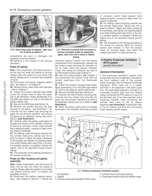 152
152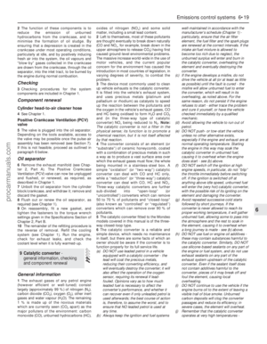 153
153 154
154 155
155 156
156 157
157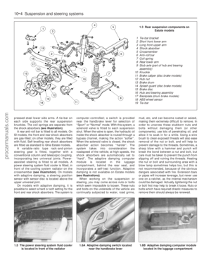 158
158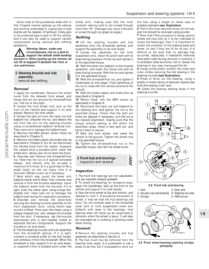 159
159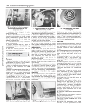 160
160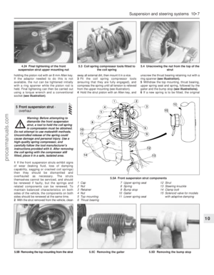 161
161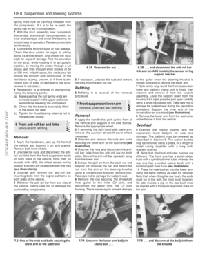 162
162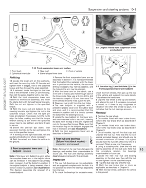 163
163 164
164 165
165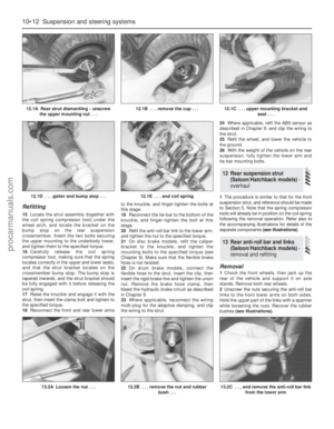 166
166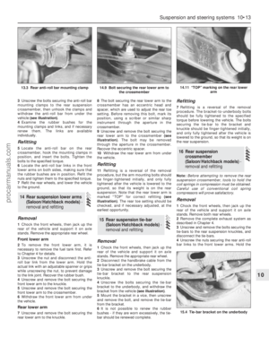 167
167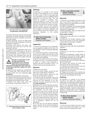 168
168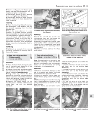 169
169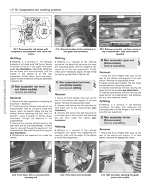 170
170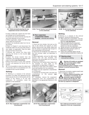 171
171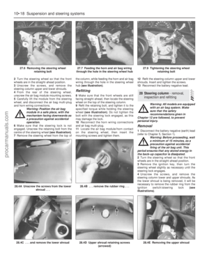 172
172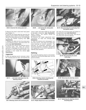 173
173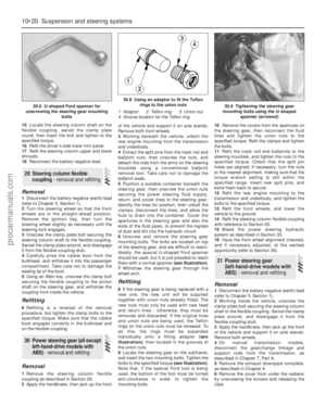 174
174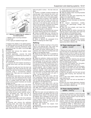 175
175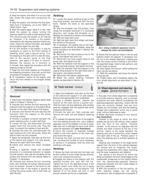 176
176 177
177 178
178 179
179 180
180 181
181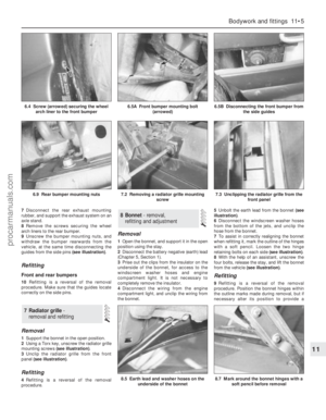 182
182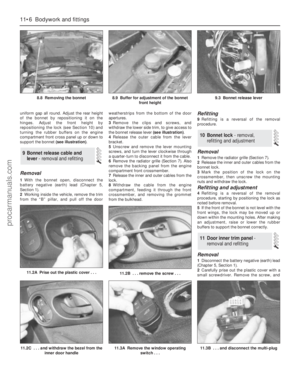 183
183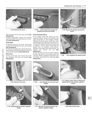 184
184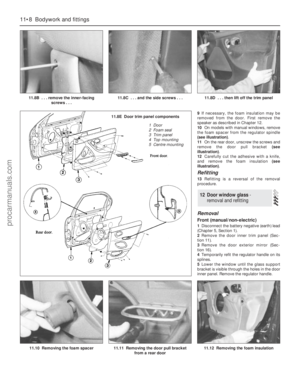 185
185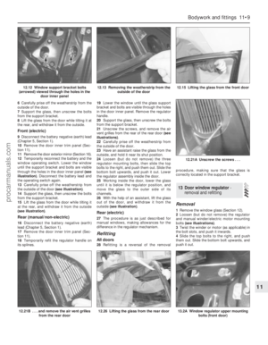 186
186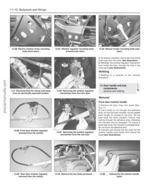 187
187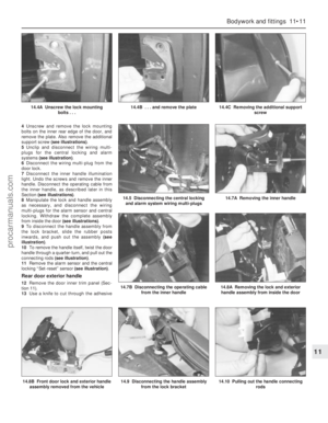 188
188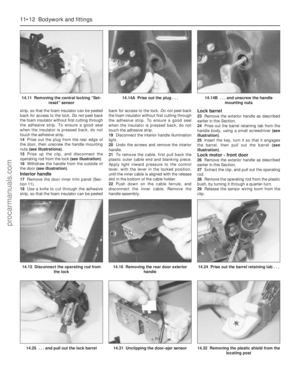 189
189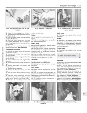 190
190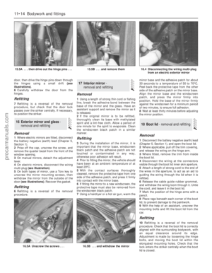 191
191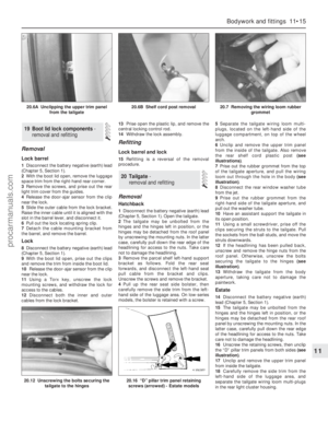 192
192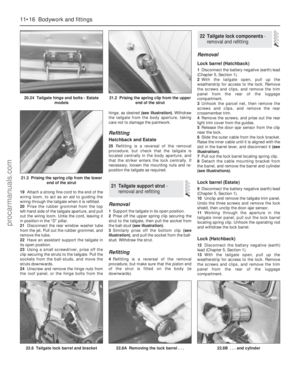 193
193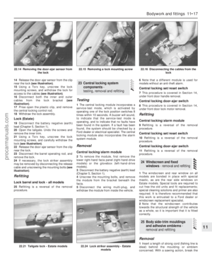 194
194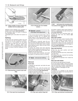 195
195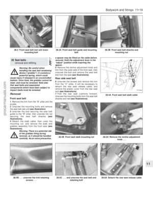 196
196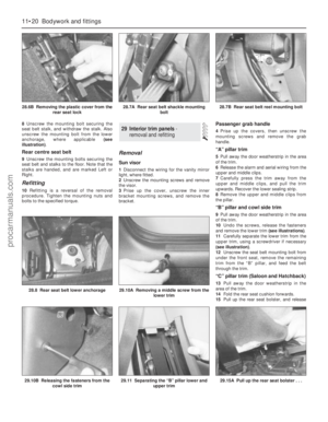 197
197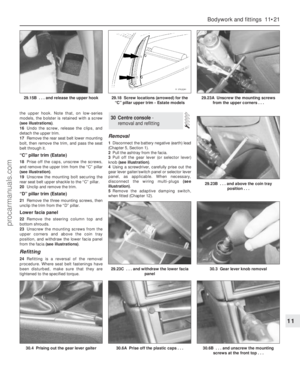 198
198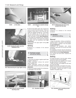 199
199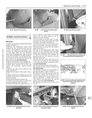 200
200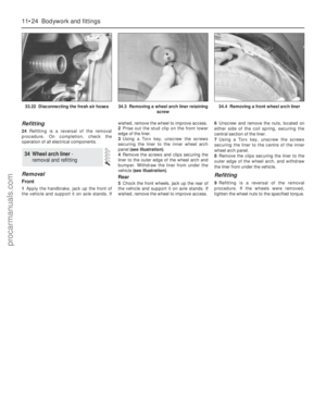 201
201 202
202 203
203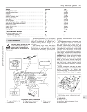 204
204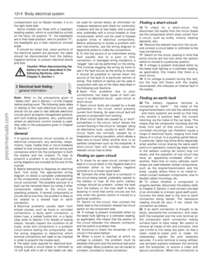 205
205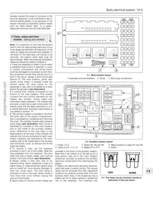 206
206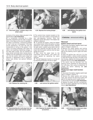 207
207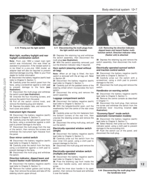 208
208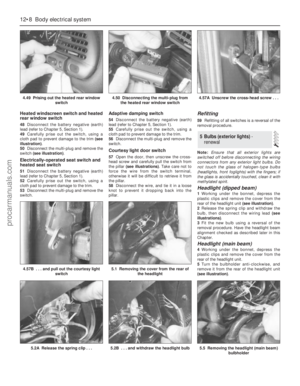 209
209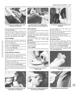 210
210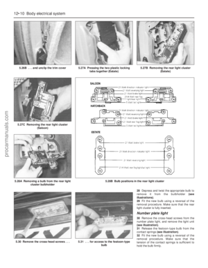 211
211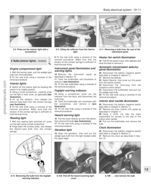 212
212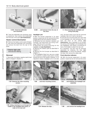 213
213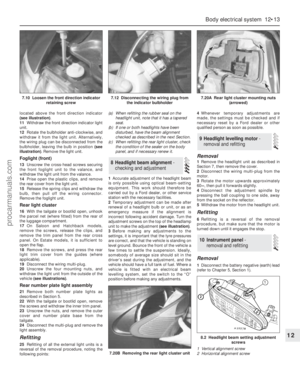 214
214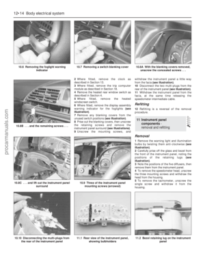 215
215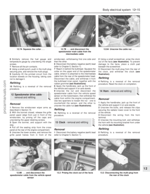 216
216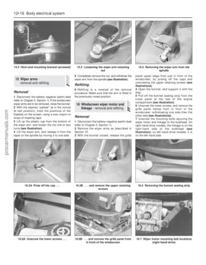 217
217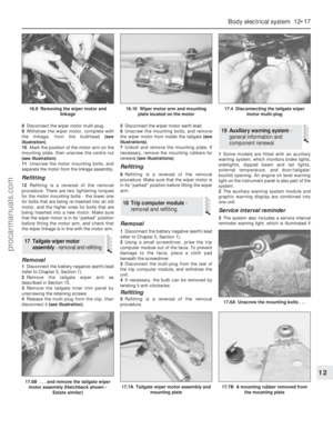 218
218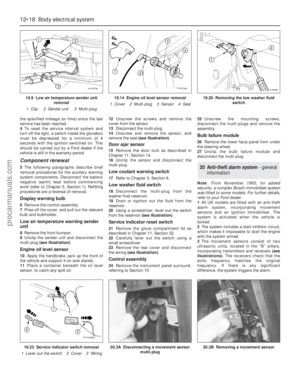 219
219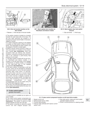 220
220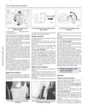 221
221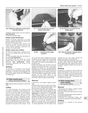 222
222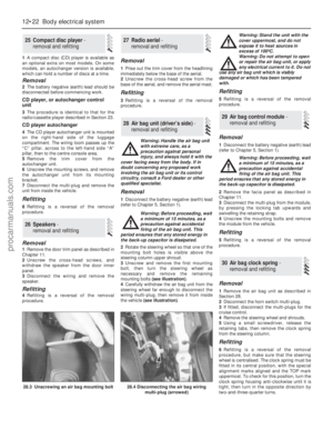 223
223 224
224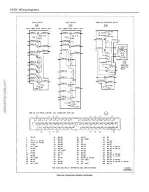 225
225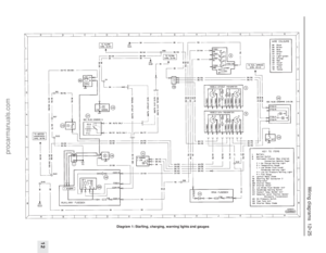 226
226 227
227 228
228 229
229 230
230 231
231 232
232 233
233 234
234 235
235 236
236 237
237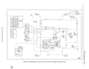 238
238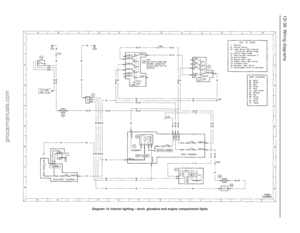 239
239 240
240 241
241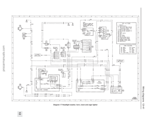 242
242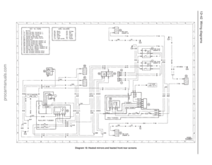 243
243 244
244 245
245 246
246 247
247 248
248 249
249 250
250 251
251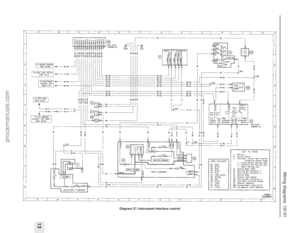 252
252 253
253 254
254 255
255 256
256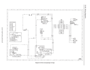 257
257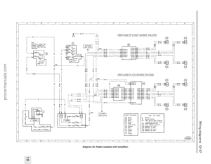 258
258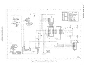 259
259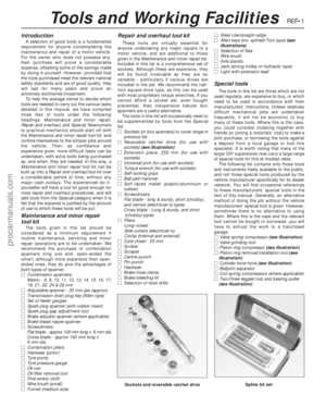 260
260 261
261 262
262 263
263 264
264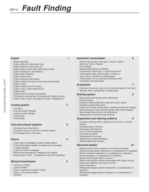 265
265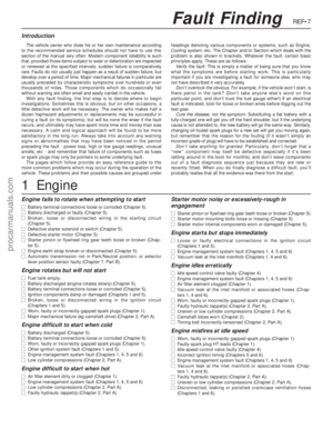 266
266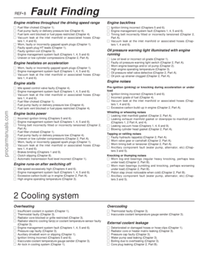 267
267 268
268 269
269 270
270 271
271 272
272 273
273 274
274 275
275 276
276 277
277 278
278