Page 65 of 279
. Unbolt the pulse-air filter housing from the
mounting bracket, th")
resonator to the air mass meter and plenum
chamber hoses, then swing the resonator up
clear of the thermostat housing (see Chapter
4). Unbolt the pulse-air filter housing from the
mounting bracket, then unfasten thebolts/nuts securing the mounting to the
subframe, unscrew the centre bolt and
withdraw the mounting; note the location of
the wiring connector bracket. The mounting’s
bracket can be unbolted from the
transmission if required (see illustration).
9On refitting, ensure that the mounting-to-
transmission bolts are securely tightened,
then refit the mounting and wiring connector
bracket. Tighten first the mounting-to-
subframe bolts/nuts, noting that these are to
be tightened in two stages to the final
specified torque wrench setting. Finally
tighten the mounting’s centre bolt, again to
the specified torque wrench setting.
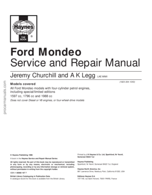
Right-hand mounting
10Unscrew the nuts and withdraw the
bracket; note that these nuts are self-locking,
and must therefore be renewed wheneverthey are disturbed. Unbolt the mounting from
the body (see illustration).
11Where hydraulic-type mountings are
fitted - there are only five nuts securing the
bracket, and the mounting is clearly
identifiable from its shape - take care never to
tilt these more than 5° from the vertical (see
illustration).
12On refitting, renew the self-locking nuts,
and tighten all fasteners to the torque wrench
settings specified. When tightening the nuts,
tighten first the four bracket-to-engine nuts,
then release the hoist or jack to allow the
engine/transmission’s weight to rest on the
mounting. Do not allow the mounting to twist
as the last two of the nuts are tightened (see
illustration).
Left-hand mounting
13Unplugging the two electrical connectors,
disconnecting the vacuum hose (where fitted)
and disconnecting the crankcase breather
hose from the cylinder head cover, remove
the complete air cleaner assembly with the air
mass meter, the resonator and the plenum
chamber (see Chapter 4).
14Unscrew the three nuts to release the
mounting from the transmission, then unbolt
it from the body (see illustration). Note that
In-car engine repair procedures 2A•25
2A
22.14 Engine/transmission left-hand
mounting - manual transmission shown,
automatic equivalent similar
1 Mounting bracket
2 Mounting
3 Transmission
4 Studs
5 Fastening plate - where fitted
22.12 When reassembling
engine/transmission right-hand mounting,
tighten nuts “A” first, release lifting
equipment, then tighten remaining
nuts “B” - do not allow mounting to twist
when doing so
22.15 Engine/transmission left-hand
mounting is secured by self-locking nuts
“A” to transmission, by bolts “B” to body22.16 Where vehicle is fitted with
automatic transmission, additional damper
may be fastened to underside of engine/
transmission rear mounting, as shown
22.10 Engine/transmission right-hand
mounting - standard type
1 Bracket
2 Mounting
3 Brackets bolted to cylinder block/crankcase
4 Vehicle body22.11 Engine/transmission right-hand
mounting - hydraulic type (where fitted)
1 Bracket
2 Hydraulic mounting
3 Brackets bolted to cylinder block/crankcase
4 Vehicle body
procarmanuals.com
Page 66 of 279

the nuts are self-locking, and must therefore
be renewed whenever they are disturbed.
Unscrew the centre bolt to dismantle the
mounting, if necessary to renew components.
15On refitting, renew the self-locking nuts,
and do not allow the mounting to twist as the
nuts are tightened (see illustration). Tighten
all fasteners to the specified torque wrench
settings.Rear mounting
16Where the vehicle is fitted with automatic
transmission, a separate damper may be
fitted beneath the subframe, which must be
unbolted to reach the mounting’s fasteners
(see illustration).
17Unbolt the mounting from the subframe,
then unscrew the mounting’s centre bolt. If
required, unbolt the mounting’s bracket fromthe transmission (see illustrations).
18On refitting, ensure that the mounting-to-
transmission bolts are securely tightened,
then refit the mounting. Tighten first the
mounting-to-subframe bolts, noting that
these are to be tightened in two stages to the
final specified torque wrench setting. Finally
tighten the mounting’s centre bolt, again to
the specified torque wrench setting.
2A•26 In-car engine repair procedures
22.17A Engine/transmission rear mounting -
manual transmission type
1 Transmission 4 Mounting
2 Mounting bracket 5 Mounting centre bolt
3 Front suspension subframe
22.17B Engine/transmission rear mounting - automatic transmission type
1 Transmission 3 Mounting 5 Mounting centre bolt
2 Mounting bracket 4 Front suspension subframe
procarmanuals.com
Page 67 of 279

Chapter 2 Part B: Engine removal
and general engine overhaul procedures
Compression test - description and interpretation . . . See Chapter 2A
Crankshaft - inspection . . . . . . . . . . . . . . . . . . . . . . . . . . . . . . . . . . . 13
Crankshaft - refitting and main bearing running
clearance check . . . . . . . . . . . . . . . . . . . . . . . . . . . . . . . . . . . . . . 17
Crankshaft - removal . . . . . . . . . . . . . . . . . . . . . . . . . . . . . . . . . . . . . 10
Cylinder block/crankcase - cleaning and inspection . . . . . . . . . . . . 11
Cylinder head - dismantling . . . . . . . . . . . . . . . . . . . . . . . . . . . . . . . 6
Cylinder head - reassembly . . . . . . . . . . . . . . . . . . . . . . . . . . . . . . . 8
Cylinder head and valve components - cleaning and inspection . . . 7
Engine - initial start-up after overhaul . . . . . . . . . . . . . . . . . . . . . . . . 19
Engine overhaul - dismantling sequence . . . . . . . . . . . . . . . . . . . . . 5Engine overhaul - general information . . . . . . . . . . . . . . . . . . . . . . . 2
Engine overhaul - reassembly sequence . . . . . . . . . . . . . . . . . . . . . 15
Engine/transmission - removal and refitting . . . . . . . . . . . . . . . . . . . 4
Engine/transmission removal - methods and precautions . . . . . . . . 3
General information . . . . . . . . . . . . . . . . . . . . . . . . . . . . . . . . . . . . . . 1
Main and big-end bearings - inspection . . . . . . . . . . . . . . . . . . . . . . 14
Piston/connecting rod assemblies - inspection . . . . . . . . . . . . . . . . 12
Piston/connecting rod assemblies - refitting and
big-end bearing running clearance check . . . . . . . . . . . . . . . . . . . 18
Piston/connecting rod assemblies - removal . . . . . . . . . . . . . . . . . . 9
Piston rings - refitting . . . . . . . . . . . . . . . . . . . . . . . . . . . . . . . . . . . . 16
Cylinder head
Maximum permissible gasket surface distortion . . . . . . . . . . . . . . . . . . 0.10 mm
Valve seat included angle . . . . . . . . . . . . . . . . . . . . . . . . . . . . . . . . . . . . 90°
Valve guide bore . . . . . . . . . . . . . . . . . . . . . . . . . . . . . . . . . . . . . . . . . . . 6.060 to 6.091 mm
Valves - generalInlet Exhaust
Valve lift . . . . . . . . . . . . . . . . . . . . . . . . . . . . . . . . . . . . . . . . . . . . . . . . . . 7.500 to 7.685 mm7.610 to 7.765 mm
Valve length . . . . . . . . . . . . . . . . . . . . . . . . . . . . . . . . . . . . . . . . . . . . . . . 96.870 to 97.330 mm 96.470 to 96.930 mm
Valve head diameter:
1.6 litre engine . . . . . . . . . . . . . . . . . . . . . . . . . . . . . . . . . . . . . . . . . . . 26.0 mm 24.5 mm
1.8 and 2.0 litre engines . . . . . . . . . . . . . . . . . . . . . . . . . . . . . . . . . . . 32.0 mm 28.0 mm
Valve stem diameter . . . . . . . . . . . . . . . . . . . . . . . . . . . . . . . . . . . . . . . . 6.028 to 6.043 mm 6.010 to6.025 mm
Valve stem-to-guide clearance . . . . . . . . . . . . . . . . . . . . . . . . . . . . . . . . 0.017 to 0.064 mm 0.035 to 0.081 mm
Cylinder block
Cylinder bore diameter - 1.6 litre engine:
Class 1 . . . . . . . . . . . . . . . . . . . . . . . . . . . . . . . . . . . . . . . . . . . . . . . . . 76.000 to 76.010 mm
Class 2 . . . . . . . . . . . . . . . . . . . . . . . . . . . . . . . . . . . . . . . . . . . . . . . . . 76.010 to 76.020 mm
Class 3 . . . . . . . . . . . . . . . . . . . . . . . . . . . . . . . . . . . . . . . . . . . . . . . . . 76.020 to 76.030 mm
Cylinder bore diameter - 1.8 litre engine:
Class 1 . . . . . . . . . . . . . . . . . . . . . . . . . . . . . . . . . . . . . . . . . . . . . . . . . 80.600 to 80.610 mm
Class 2 . . . . . . . . . . . . . . . . . . . . . . . . . . . . . . . . . . . . . . . . . . . . . . . . . 80.610 to 80.620 mm
Class 3 . . . . . . . . . . . . . . . . . . . . . . . . . . . . . . . . . . . . . . . . . . . . . . . . . 80.620 to 80.630 mm
Cylinder bore diameter - 2.0 litre engine:
Class 1 . . . . . . . . . . . . . . . . . . . . . . . . . . . . . . . . . . . . . . . . . . . . . . . . . 84.800 to 84.810 mm
Class 2 . . . . . . . . . . . . . . . . . . . . . . . . . . . . . . . . . . . . . . . . . . . . . . . . . 84.810 to 84.820 mm
Class 3 . . . . . . . . . . . . . . . . . . . . . . . . . . . . . . . . . . . . . . . . . . . . . . . . . 84.820 to 84.830 mm
2B•1
Easy,suitable for
novice with little
experienceFairly easy,suitable
for beginner with
some experienceFairly difficult,suitable
for competent DIY
mechanicDifficult,suitable for
experienced DIY
mechanicVery difficult,
suitable for expert DIY
or professional
Degrees of difficulty
Specifications Contents2B
procarmanuals.com
Page 68 of 279

Pistons and piston rings
Piston diameter - 1.6 litre engine:
Class 1 . . . . . . . . . . . . . . . . . . . . . . . . . . . . . . . . . . . . . . . . . . . . . . . . . 75.975 to 75.985 mm
Class 2 . . . . . . . . . . . . . . . . . . . . . . . . . . . . . . . . . . . . . . . . . . . . . . . . . 75.985 to 75.995 mm
Class 3 . . . . . . . . . . . . . . . . . . . . . . . . . . . . . . . . . . . . . . . . . . . . . . . . . 75.995 to 76.005 mm
Piston diameter - 1.8 litre engine:
Class 1 . . . . . . . . . . . . . . . . . . . . . . . . . . . . . . . . . . . . . . . . . . . . . . . . . 80.570 to 80.580 mm
Class 2 . . . . . . . . . . . . . . . . . . . . . . . . . . . . . . . . . . . . . . . . . . . . . . . . . 80.580 to 80.590 mm
Class 3 . . . . . . . . . . . . . . . . . . . . . . . . . . . . . . . . . . . . . . . . . . . . . . . . . 80.590 to 80.600 mm
Piston diameter - 2.0 litre engine:
Class 1 . . . . . . . . . . . . . . . . . . . . . . . . . . . . . . . . . . . . . . . . . . . . . . . . . 84.770 to 84.780 mm
Class 2 . . . . . . . . . . . . . . . . . . . . . . . . . . . . . . . . . . . . . . . . . . . . . . . . . 84.780 to 84.790 mm
Class 3 . . . . . . . . . . . . . . . . . . . . . . . . . . . . . . . . . . . . . . . . . . . . . . . . . 84.790 to 84.800 mm
Oversizes - all engines . . . . . . . . . . . . . . . . . . . . . . . . . . . . . . . . . . . . . . None available
Piston-to-cylinder bore clearance . . . . . . . . . . . . . . . . . . . . . . . . . . . . . . No information available at time of writing
Piston ring end gaps - installed:
Top compression ring - 1.6 and 1.8 litre engines . . . . . . . . . . . . . . . . 0.30 to 0.50 mm
Top compression ring - 2.0 litre engine . . . . . . . . . . . . . . . . . . . . . . . 0.26 to 0.50 mm
Second compression ring . . . . . . . . . . . . . . . . . . . . . . . . . . . . . . . . . . 0.30 to 0.50 mm
Oil control ring - 1.6 litre engine . . . . . . . . . . . . . . . . . . . . . . . . . . . . . 0.25 to 1.00 mm
Oil control ring - 1.8 litre engine . . . . . . . . . . . . . . . . . . . . . . . . . . . . . 0.38 to 1.14 mm
Oil control ring - 2.0 litre engine . . . . . . . . . . . . . . . . . . . . . . . . . . . . . 0.40 to 1.40 mm
Gudgeon pin
Diameter:
White colour code/piston crown marked “A” . . . . . . . . . . . . . . . . . . . 20.622 to 20.625 mm
Red colour code/piston crown marked “B” . . . . . . . . . . . . . . . . . . . . 20.625 to 20.628 mm
Blue colour code/piston crown marked “C” . . . . . . . . . . . . . . . . . . . . 20.628 to 20.631 mm
Clearance in piston . . . . . . . . . . . . . . . . . . . . . . . . . . . . . . . . . . . . . . . . . 0.010 to 0.016 mm
Connecting rod small-end eye internal diameter . . . . . . . . . . . . . . . . . . 20.589 to 20.609 mm
Interference fit in connecting rod . . . . . . . . . . . . . . . . . . . . . . . . . . . . . . 0.011 to 0.042 mm
Crankshaft and bearings
Main bearing shell standard inside diameter - installed . . . . . . . . . . . . 58.011 to 58.038 mm
Main bearing journal standard diameter . . . . . . . . . . . . . . . . . . . . . . . . 57.980 to 58.000 mm
Main bearing journal-to-shell running clearance . . . . . . . . . . . . . . . . . . 0.011 to 0.058 mm
Main bearing shell undersizes available . . . . . . . . . . . . . . . . . . . . . . . . . 0.02 mm, 0.25 mm
Big-end bearing shell standard inside diameter - installed . . . . . . . . . . . 46.926 to 46.960 mm
Crankpin (big-end) bearing journal standard diameter . . . . . . . . . . . . . 46.890 to 46.910 mm
Crankpin (big-end) bearing journal-to-shell running clearance . . . . . . . . 0.016 to 0.070 mm
Big-end bearing shell undersizes available . . . . . . . . . . . . . . . . . . . . . . 0.02 mm, 0.25 mm
Crankshaft endfloat . . . . . . . . . . . . . . . . . . . . . . . . . . . . . . . . . . . . . . . . . 0.090 to 0.310 mm
Torque wrench settingsNm lbf ft
Main bearing cap bolts and nuts . . . . . . . . . . . . . . . . . . . . . . . . . . . . . . 80 59
Big-end bearing cap bolts:
Stage 1 . . . . . . . . . . . . . . . . . . . . . . . . . . . . . . . . . . . . . . . . . . . . . . . . 18 13
Stage 2 . . . . . . . . . . . . . . . . . . . . . . . . . . . . . . . . . . . . . . . . . . . . . . . . Angle-tighten a further 90°
Piston-cooling oil jet/blanking plug Torx screws . . . . . . . . . . . . . . . . . . 10 7
Cylinder block and head oilway blanking plugs:
M6 x 10 . . . . . . . . . . . . . . . . . . . . . . . . . . . . . . . . . . . . . . . . . . . . . . . . 8 to 11 6 to 8
M10 x 11.5 - in block . . . . . . . . . . . . . . . . . . . . . . . . . . . . . . . . . . . . . . 24 17
1/4 PTF plug - in block . . . . . . . . . . . . . . . . . . . . . . . . . . . . . . . . . . . . 25 18
Power steering pump/air conditioning compressor mounting
bracket-to-cylinder block bolts . . . . . . . . . . . . . . . . . . . . . . . . . . . . . . . . 47 35
Exhaust manifold heat shield mounting bracket-to-cylinder
block bolts . . . . . . . . . . . . . . . . . . . . . . . . . . . . . . . . . . . . . . . . . . . . . . . . 32 24
Crankcase breather system:
Oil separator-to-cylinder block bolts . . . . . . . . . . . . . . . . . . . . . . . . . 10 7
Pipe-to-cylinder head bolt . . . . . . . . . . . . . . . . . . . . . . . . . . . . . . . . . . 23 17
Water pump bolts . . . . . . . . . . . . . . . . . . . . . . . . . . . . . . . . . . . . . . . . . . See Chapter 3
Driveshaft support bearing bracket-to-cylinder block bolts . . . . . . . . . . 48 35
Transmission-to-engine bolts . . . . . . . . . . . . . . . . . . . . . . . . . . . . . . . . . See Part A of this Chapter
Engine/transmission mounting fasteners . . . . . . . . . . . . . . . . . . . . . . . . See Part A of this Chapter
Front suspension subframe bolts . . . . . . . . . . . . . . . . . . . . . . . . . . . . . . 130 96
Note:Refer to Part A of this Chapter for remaining torque wrench settings.
2B•2 Engine removal and general engine overhaul procedures
procarmanuals.com
Page 69 of 279

How to use this Chapter
This Part of Chapter 2 is devoted to
engine/transmission removal and refitting, to
those repair procedures requiring the removal
of the engine/transmission from the vehicle,
and to the overhaul of engine components. It
includes only the Specifications relevant to
those procedures. Refer to Part A for
additional Specifications, if required.
General information
The information ranges from advice
concerning preparation for an overhaul and
the purchase of replacement parts, to detailed
step-by-step procedures covering removal
and installation of internal engine components
and the inspection of parts.
The following Sections have been written
based on the assumption that the engine has
been removed from the vehicle. For
information concerning in-vehicle engine
repair, as well as removal and installation of
the external components necessary for the
overhaul, see Part A of this Chapter and
Section 5 of this Part.
When overhauling this engine, it is essential
to establish first exactly what replacement
parts are available. At the time of writing,
components such as the piston rings are not
available separately from the
piston/connecting rod assemblies; pistons,
gudgeon pins and valve guides are not
available separately, and very few under- or
oversized components are available for
engine reconditioning. In most cases, it would
appear that the easiest and most
economically-sensible course of action is to
replace a worn or damaged engine with an
exchange unit.
It’s not always easy to determine when, or
if, an engine should be completely
overhauled, as a number of factors must be
considered.
High mileage is not necessarily an
indication that an overhaul is needed, while
low mileage doesn’t preclude the need for an
overhaul. Frequency of servicing is probably
the most important consideration. An engine
that’s had regular and frequent oil and filter
changes, as well as other required
maintenance, will most likely give many
thousands of miles of reliable service.
Conversely, a neglected engine may require
an overhaul very early in its life.
Excessive oil consumption is an indication
that piston rings, valve seals and/or valve
guides are in need of attention. Make surethat oil leaks aren’t responsible before
deciding that the rings and/or guides are
worn. Perform a cylinder compression check
(Part A of this Chapter, Section 3) to
determine the extent of the work required.
Loss of power, rough running, knocking or
metallic engine noises, excessive valve train
noise and high fuel consumption rates may
also point to the need for an overhaul,
especially if they’re all present at the same
time. If a full service doesn’t remedy the
situation, major mechanical work is the only
solution.
An engine overhaul involves restoring all
internal parts to the specification of a new
engine. Note:Always check first what
replacement parts are available before
planning any overhaul operation; refer to
Section 1 of this Part. Ford dealers, or a good
engine reconditioning specialist/automotive
parts supplier may be able to suggest
alternatives which will enable you to overcome
the lack of replacement parts.
During an overhaul, it is usual to renew the
piston rings, and to rebore and/or hone the
cylinder bores; where the rebore is done by an
automotive machine shop, new oversize
pistons and rings will also be installed - all
these operations, of course, assume the
availability of suitable replacement parts. The
main and big-end bearings are generally
renewed and, if necessary, the crankshaft
may be reground to restore the journals.
Generally, the valves are serviced as well,
since they’re usually in less-than-perfect
condition at this point. While the engine is
being overhauled, other components, such as
the starter and alternator, can be renewed as
well, or rebuilt, if the necessary parts can be
found. The end result should be an as-new
engine that will give many trouble-free miles.
Note:Critical cooling system components
such as the hoses, drivebelt, thermostat and
water pump MUST be replaced with new
parts when an engine is overhauled. The
radiator should be checked carefully, to
ensure that it isn’t clogged or leaking (see
Chapter 3). Also, as a general rule, the oil
pump should be renewed when an engine is
rebuilt.
Before beginning the engine overhaul, read
through the entire procedure to familiarise
yourself with the scope and requirements of
the job. Overhauling an engine isn’t difficult,
but it is time-consuming. Plan on the vehicle
being off the road for a minimum of two
weeks, especially if parts must be taken to an
automotive machine shop for repair or
reconditioning. Check on availability of parts,
and make sure that any necessary special
tools and equipment are obtained in advance.
Most work can be done with typical hand
tools, although a number of precision
measuring tools are required, for inspecting
parts to determine if they must be replaced.
Often, an automotive machine shop will
handle the inspection of parts, and will offer
advice concerning reconditioning andreplacement. Note:Always wait until the
engine has been completely dismantled, and
all components, especially the cylinder
block/crankcase, have been inspected, before
deciding what service and repair operations
must be performed by an automotive machine
shop. Since the block’s condition will be the
major factor to consider when determining
whether to overhaul the original engine or buy
a rebuilt one, never purchase parts or have
machine work done on other components
until the cylinder block/crankcase has been
thoroughly inspected.As a general rule, time
is the primary cost of an overhaul, so it
doesn’t pay to install worn or sub-standard
parts.
As a final note, to ensure maximum life and
minimum trouble from a rebuilt engine,
everything must be assembled with care, in a
spotlessly-clean environment.
If you’ve decided that an engine must be
removed for overhaul or major repair work,
several preliminary steps should be taken.
Locating a suitable place to work is
extremely important. Adequate work space,
along with storage space for the vehicle, will
be needed. If a workshop or garage isn’t
available, at the very least, a flat, level, clean
work surface made of concrete or asphalt is
required.
Cleaning the engine compartment and
engine/transmission before beginning the
removal procedure will help keep tools clean
and organized.
The engine can only be withdrawn by
removing it complete with the transmission;
the vehicle’s body must be raised and
supported securely, sufficiently high that the
engine/transmission can be unbolted as a
single unit and lowered to the ground; the
engine/transmission unit can then be
withdrawn from under the vehicle and
separated. An engine hoist or A-frame will
therefore be necessary. Make sure the
equipment is rated in excess of the combined
weight of the engine and transmission. Safety
is of primary importance, considering the
potential hazards involved in removing the
engine/transmission from the vehicle.
If this is the first time you have removed an
engine, a helper should ideally be available.
Advice and aid from someone more
experienced would also be helpful. There are
many instances when one person cannot
simultaneously perform all of the operations
required when removing the engine/
transmission from the vehicle.
Plan the operation ahead of time. Arrange for,
or obtain, all of the tools and equipment you’ll
need prior to beginning the job. Some of the
equipment necessary to perform
engine/transmission removal and installation
3 Engine/transmission removal -
methods and precautions
2 Engine overhaul -
general information
1 General information
Engine removal and general engine overhaul procedures 2B•3
2B
procarmanuals.com
Page 70 of 279
 a heavy-duty trolley
jack, a strong pair of axle stands, some wooden
blocks, and a")
safely and with relative ease, and which may
have to be hired or borrowed, includes (in
addition to the engine hoist) a heavy-duty trolley
jack, a strong pair of axle stands, some wooden
blocks, and an engine dolly (a low, wheeled
platform capable of taking the weight of the
engine/transmission, so that it can be moved
easily when on the ground). A complete set of
spanners and sockets (as described in the front
of this manual) will obviously be needed,
together with plenty of rags and cleaning
solvent for mopping-up spilled oil, coolant and
fuel. If the hoist is to be hired, make sure that
you arrange for it in advance, and perform all of
the operations possible without it beforehand.
This will save you money and time.
Plan for the vehicle to be out of use for
quite a while. A machine shop will be required
to perform some of the work which the do-it-
yourselfer can’t accomplish without special
equipment. These establishments often have
a busy schedule, so it would be a good idea
to consult them before removing the engine,
to accurately estimate the amount of time
required to rebuild or repair components that
may need work.
Always be extremely careful when removing
and installing the engine/transmission.
Serious injury can result from careless
actions. By planning ahead and taking your
time, the job (although a major task) can be
accomplished successfully.
Warning: Petrol is extremely
flammable, so take extra
precautions when disconnecting
any part of the fuel system. Don’t
smoke, or allow naked flames or bare light
bulbs in or near the work area, and don’t
work in a garage where a natural gas
appliance (such as a clothes dryer or water
heater) is installed. If you spill petrol on
your skin, rinse it off immediately. Have a
fire extinguisher rated for petrol fires
handy, and know how to use it.Note: Read through the entire Section, as well
as reading the advice in the preceding Section,
before beginning this procedure. The engine
and transmission are removed as a unit,
lowered to the ground and removed from
underneath, then separated outside the vehicle.
Removal
1Park the vehicle on firm, level ground, apply
the handbrake firmly, and slacken the nuts
securing both front roadwheels.
2Relieve the fuel system pressure (see
Chapter 4).
3Disconnect the battery negative (earth) lead
- see Chapter 5, Section 1. For better access
the battery may be removed completely (see
Chapter 5).
4Place protective covers on the wings and
engine compartment front crossmember, then
remove the bonnet (see Chapter 11).
5Whenever you disconnect any vacuum
lines, coolant and emissions hoses, wiring
loom connectors, earth straps and fuel lines
as part of the following procedure, always
label them clearly, so that they can be
correctly reassembled.
6Unplug the two electrical connectors,disconnect the vacuum hose (where fitted)
and disconnect the crankcase breather hose
from the cylinder head cover, then remove the
complete air cleaner assembly, with the air
mass meter, the resonator and the plenum
chamber (see Chapter 4).
7Equalise the pressure in the fuel tank by
removing the filler cap, then undo the fuel
feed and return lines connecting the engine to
the chassis (see Chapter 4). Plug or cap all
open fittings (see illustration).
8Disconnect the accelerator cable from the
throttle linkage as described in Chapter 4 -
where fitted, also disconnect the cruise
control actuator cable (see Chapter 12).
Secure the cable(s) clear of the
engine/transmission.
9Releasing its wire clip, unplug the power
steering pressure switch electrical connector,
then unbolt the power steering high-pressure
pipe and the earth lead from the cylinder head
rear support plate/engine lifting eye (see
illustrations).
10Marking or labelling all components as
they are disconnected (see paragraph 5
above), disconnect the vacuum hoses as
follows:
4 Engine/transmission -
removal and refitting
2B•4 Engine removal and general engine overhaul procedures
4.7 Note colour-coding of unions when
disconnecting fuel feed and return lines4.9A Unplug the power steering pressure
switch electrical connector . . .4.9B . . . unbolt the power steering high-
pressure pipe . . .
Whenever any wiring is disconnected, . . . vacuum hoses and pipes should
mark or label it as shown, to ensure be similarly marked
correct reconnection . . .
Masking tape and/or a touch-up paint applicator work well for marking items. Take
instant photos, or sketch the locations of components and brackets.
procarmanuals.com
Page 71 of 279
 One from the rear of the throttle housing
(only the one hose - there is no need to
disconnect the second hose running to
the fuel pressure regulator) (see
illustration).
(b) One from the union on")
(a) One from the rear of the throttle housing
(only the one hose - there is no need to
disconnect the second hose running to
the fuel pressure regulator) (see
illustration).
(b) One from the union on the inlet manifold’s
left-hand end (see illustration).
(c) The braking system vacuum servo unit
hose - from the inlet manifold (see
Chapter 9 for details).
(d) Also disconnect the vacuum hoses from
the Exhaust Gas Recirculation system
components - one from the EGR valve,
two from the EGR pipe (note that these
last two are of different sizes, as are their
pipe stubs, so that they can only be
connected the correct way round).
(e) While you are there, trace the vacuum line
from the pulse-air filter housing over the
top of the transmission, and disconnect it
by pulling the plastic pipe out of the
rubber hose just beneath the bulkhead-
mounted pulse-air solenoid valve (see
illustration).
(f) Secure all these hoses so that they won’t
get damaged as the engine/transmission
is removed.
11Unbolt the engine/transmission-to-body
earth lead from the transmission’s top surface
(see illustration). Disconnect the speed-
ometer drive cable (see Chapter 12) and
secure it clear of the engine/transmission.
12Where the vehicle is fitted with manual
transmission, disconnect the clutch cable (seeChapter 8). Where automatic transmission is
fitted, disconnect the selector cable (see
Chapter 7, Part B). Secure the cable clear of
the engine/transmission.
13Marking or labelling all components as
they are disconnected (see paragraph 5
above), disconnect the engine wiring loom
from the body as follows:
(a) Starting at the left-hand side of the engine
compartment, release and unplug the
three large electrical connectors clipped
to the suspension mounting - note the
wire clips fitted to some connectors (see
illustration).
(b) Disconnect and/or release the battery-to-
starter motor wiring, noting the single
connector which must be unplugged.
(c) Unplug the electrical connector(s) to
disconnect the vehicle speed sensor,
oxygen sensor and, where fitted, the oil
level sensor wiring - unclip the connectors
to release the wiring where necessary.
(d) Work along the loom to the bulkhead,
unclipping the loom and unplugging the
various bulkhead-mounted components
connected into it, until you reach the
right-hand side of the engine
compartment (see illustration).
(e) Carefully prise the power steering fluid
reservoir upwards out of its clip on the
suspension mounting, then unscrew the
ECU connector’s retaining bolt and
unplug the connector (see illustration).
(f) Unbolt the earth lead from the right-hand
Engine removal and general engine overhaul procedures 2B•5
2B
4.13A Unplug three large electrical
connectors (arrowed) . . .4.13B . . . unplug engine wiring loom from
battery wiring and bulkhead components
(arrowed) . . .4.13C . . . and disconnect ECU wiring and
earth lead (arrowed) to release engine
wiring loom from vehicle body
4.9C . . . and the earth lead from the
cylinder head rear support plate/engine
lifting eye4.10A Disconnect vacuum hose shown
from rear of throttle housing . . .4.10B . . . vacuum hose (arrowed) from
union on left-hand end on inlet manifold . . .
4.10C . . . also brake servo hose (A), EGR
valve hose (B), EGR pipe hoses (C) - noting
their different sizes - and pulse-air filter
vacuum line (D)
4.11 Unbolt the engine/transmission-to-
body earth lead - hidden behind wiring
loom guide - from location (arrowed) on
the transmission’s top surface
procarmanuals.com
Page 72 of 279
 Secure the engine wiring loom neatly to
the engine/transmission so that it cannot
be damaged as the u")
inner wing panel, release the engine
wiring loom and refit the power steering
fluid reservoir.
(g) Secure the engine wiring loom neatly to
the engine/transmission so that it cannot
be damaged as the unit is removed from
the vehicle.
14Unbolt both parts of the exhaust manifold
heat shield; unclip the coolant hose to allow
the upper part to be withdrawn.
15Remove the auxiliary drivebelt (see
Chapter 1).
16Unbolt the power steering pump (see
Chapter 10); secure it as far as possible
(without disconnecting the system’s hoses)
clear of the engine/transmission.
17Raise the vehicle and support it securely
on axle stands, then remove the front
roadwheels. Drain the cooling system and (if
the engine is to be dismantled) drain the
engine oil and remove the oil filter (see
Chapter 1). Also drain the transmission as
described in the relevant Part of Chapter 7.
18Withdraw the lower part of the exhaust
manifold heat shield.
19Unscrew the nuts to disconnect the
exhaust system front downpipe from the
manifold, then unhook all the system’s rubber
mountings and withdraw the complete
exhaust system from under the vehicle (see
Chapter 4 for details).
20Where the vehicle is fitted with manual
transmission, mark their positions, then
disconnect the gearchange linkage and
transmission support rods from the rear of the
transmission. Unscrew the retaining nuts, and
withdraw the gear linkage heat shield from the
underbody. Unbolt the rear end of the linkage
from the underbody, swivel the linkage around
to the rear, and tie it to the underbody (see
Chapter 7, Part A, for details).
21Disconnect both anti-roll bar links from
their respective suspension strut - note the
flexible brake hose bracket attached to each
link stud - and both track rod ends from their
steering knuckles. Unfasten the clamp bolt
securing each front suspension lower arm
balljoint to its steering knuckle (see Chap-
ter 10 for details). Check that both balljoints
can be released from the knuckle assemblies
when required, but leave them in place for thetime being, secured by the clamp bolts if
necessary.
22Where the vehicle is fitted with air
conditioning, unbolt the accumulator/
dehydrator from the subframe; secure it as far
as possible (without disconnecting the
system’s hoses) clear of the engine/
transmission.
Warning: Do not disconnect the
refrigerant hoses.
23Unbolt the steering gear from the
subframe; if the bolts are not accessible from
above, a Ford service tool will be required to
reach them from underneath the vehicle (see
Chapter 10 for details).
24Unscrew the two bolts securing the power
steering system pipes to the right-hand side
of the subframe.
25Hold the radiator in its raised position, by
inserting split pins through the holes in the
rear of the engine compartment front
crossmember and into the radiator’s upper
mounting extensions. Unbolt the radiator
mounting brackets from the subframe; note
that they are handed, and are marked to
ensure correct refitting (see illustrations).
Collect and store the bottom mounting
rubbers for safekeeping, noting which way up
they are fitted.
26Unbolt the engine/transmission rear
mounting from the subframe - where the
vehicle is fitted with automatic transmission, a
separate damper may be fitted beneath the
subframe, which must be unbolted to reach
the mounting’s fasteners. Where the vehicle is
fitted with manual transmission, also unscrew
the mounting centre bolt, and unbolt the
mounting bracket from the transmission.
27Unscrew the engine/transmission front
mounting centre bolt, and unbolt the
mounting from the subframe, noting the
location of the wiring connector bracket.
28Use white paint or similar (do not use a
sharp-pointed scriber, which might break the
underbody protective coating and cause
rusting) to mark the exact relationship of the
subframe to the underbody. Unscrew the four
mounting bolts from the subframe (note their
different-sized washers - see also illus-tration 4.47A) and allow the subframe to hang
down on the suspension lower arm balljoints.
Disconnect the balljoints one at a time from
the steering knuckle assemblies (see Chap-
ter 10) and lower the subframe to the ground;
withdraw the subframe from under the
vehicle.
29Marking or labelling all components as
they are disconnected (see paragraph 5
above) and catching as much as possible of
the escaping coolant in the drain tray,
disconnect the cooling system hoses and
pipes as follows - refer to Chapter 3 for further
details, if required:
(a) Remove the radiator top hose.
(b) Remove the (heater) hose running from
the thermostat to the engine
compartment bulkhead union.
(c) Disconnect from the thermostat the hose
running to the expansion tank - secure the
hose clear of the working area.
(d) Disconnect from the thermostat the
coolant hose/pipe which runs to the
radiator bottom hose.
(e) Disconnect the radiator bottom hose from
the radiator union, from the (sump) heater
coolant pipe and from the water pump
union - secure the hose clear of the
working area.
(f) Unbolt the (heater) coolant pipe from the
sump, trace the pipe/hose round to the
engine compartment bulkhead union,
disconnecting (where fitted) the oil cooler
hoses from the cooler unions, then
remove it.
(g) Unless the vehicle has air conditioning
fitted, secure the radiator as far forwards
as possible while it is in its raised position;
if air conditioning is fitted, remove the
radiator completely (see Chapter 3).
30Where the vehicle is fitted with air
conditioning, unplug the compressor’s
electrical connector, and unbolt the
compressor from the engine (see
illustration). Secure it as far as possible
(without disconnecting the system’s hoses)
clear of the engine/transmission.
Warning: Do not disconnect the
refrigerant hoses.
2B•6 Engine removal and general engine overhaul procedures
4.25A Use split pins as shown to secure
radiator in its raised position . . .
4.25B . . . while you unbolt the bottom
mountings (arrowed) - note that the
mountings are handed, and do not lose the
mounting rubbers
4.30 Unscrew bolts (arrowed) to release
air conditioning compressor from engine
procarmanuals.com
 1
1 2
2 3
3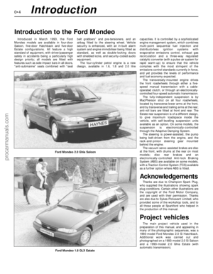 4
4 5
5 6
6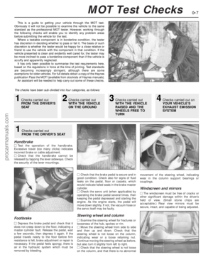 7
7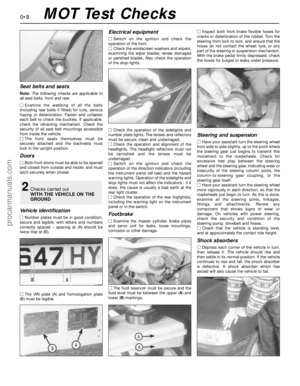 8
8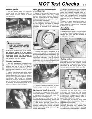 9
9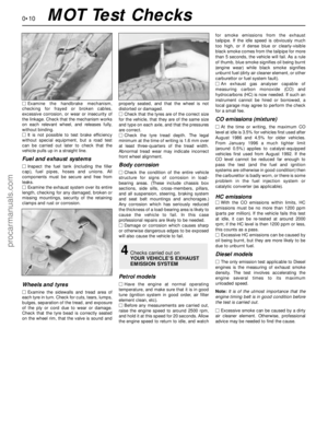 10
10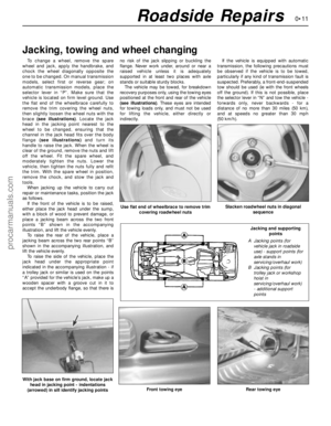 11
11 12
12 13
13 14
14 15
15 16
16 17
17 18
18 19
19 20
20 21
21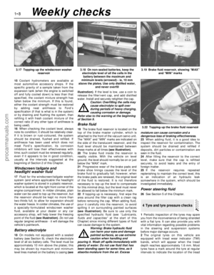 22
22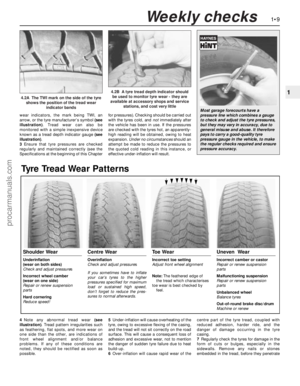 23
23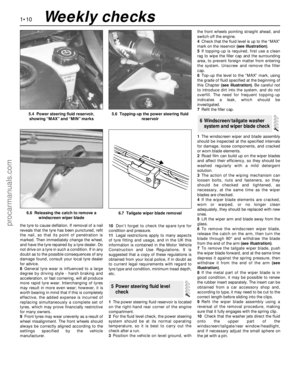 24
24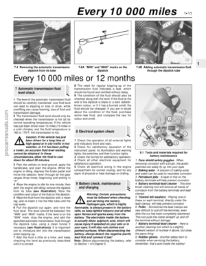 25
25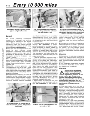 26
26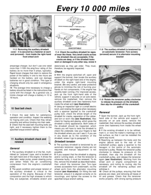 27
27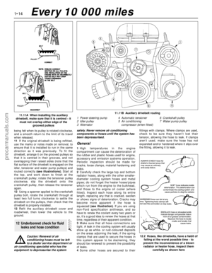 28
28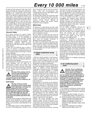 29
29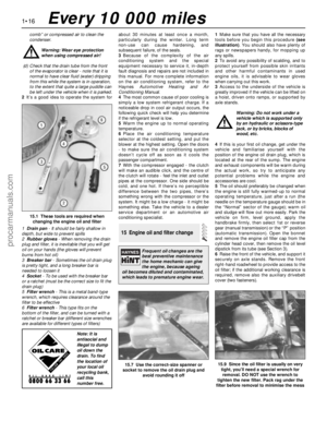 30
30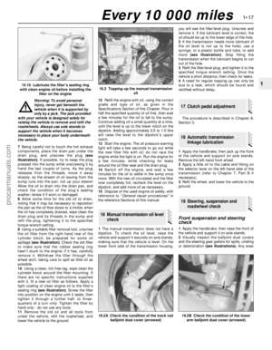 31
31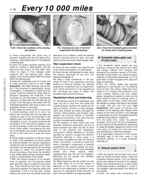 32
32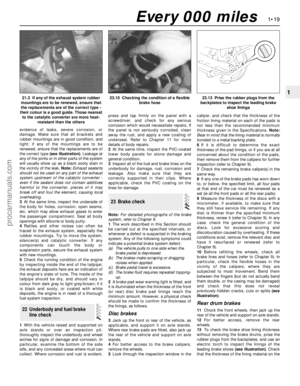 33
33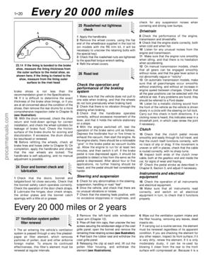 34
34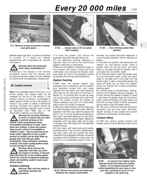 35
35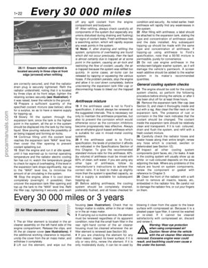 36
36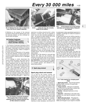 37
37 38
38 39
39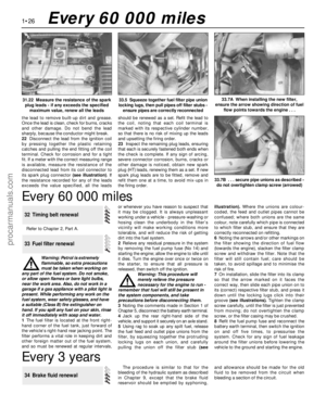 40
40 41
41 42
42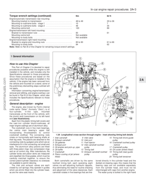 43
43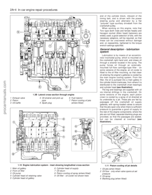 44
44 45
45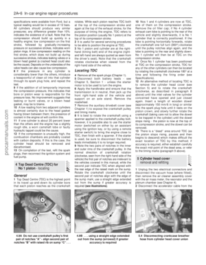 46
46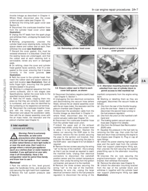 47
47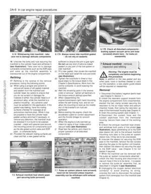 48
48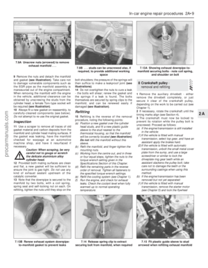 49
49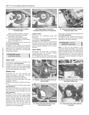 50
50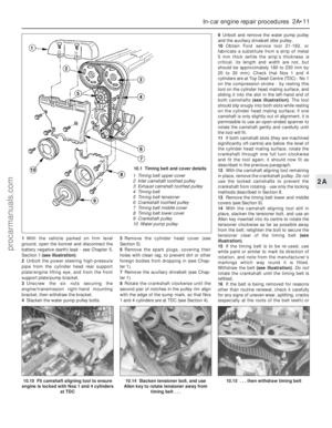 51
51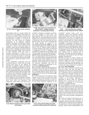 52
52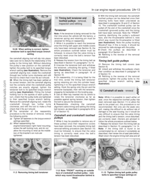 53
53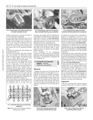 54
54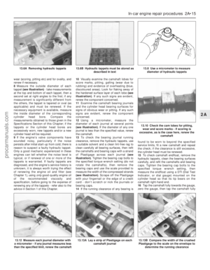 55
55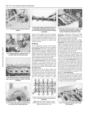 56
56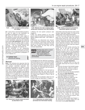 57
57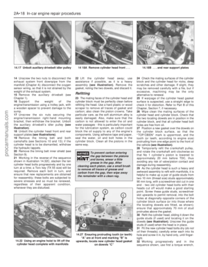 58
58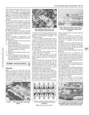 59
59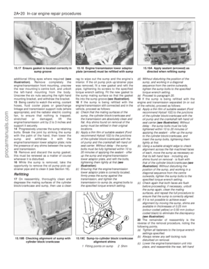 60
60 61
61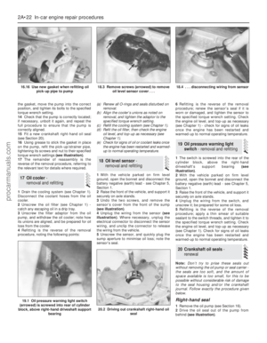 62
62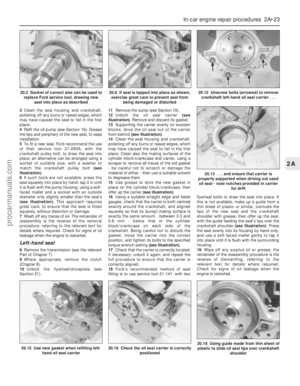 63
63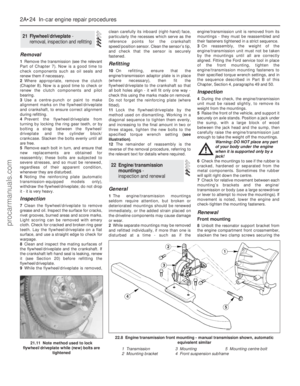 64
64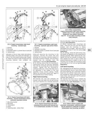 65
65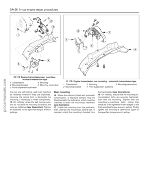 66
66 67
67 68
68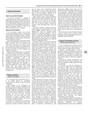 69
69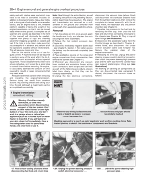 70
70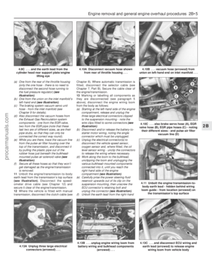 71
71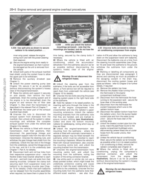 72
72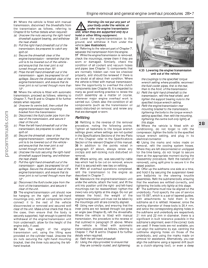 73
73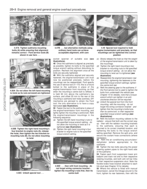 74
74 75
75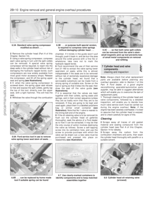 76
76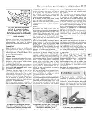 77
77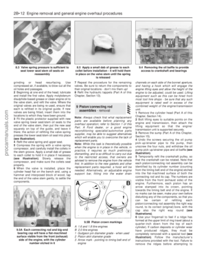 78
78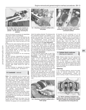 79
79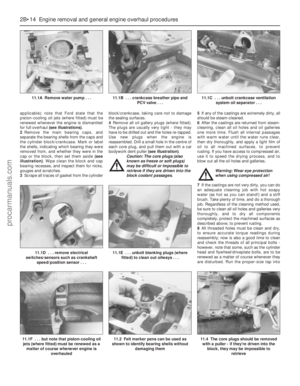 80
80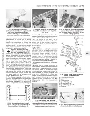 81
81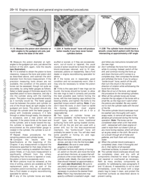 82
82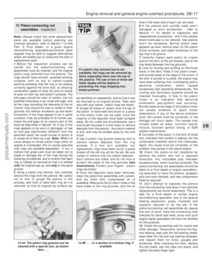 83
83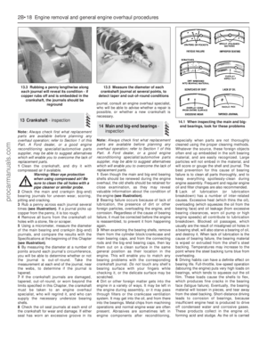 84
84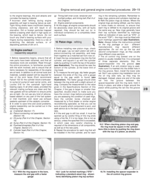 85
85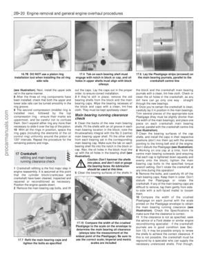 86
86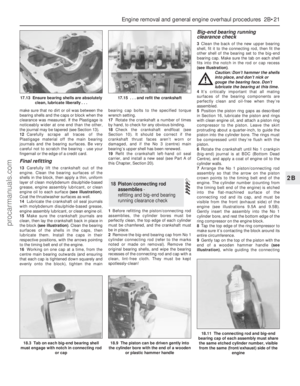 87
87 88
88 89
89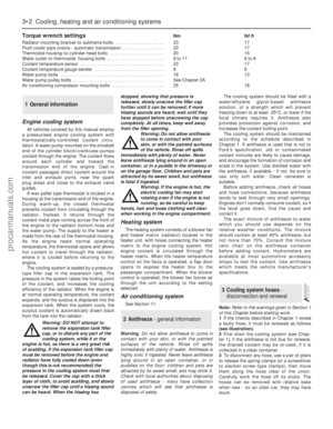 90
90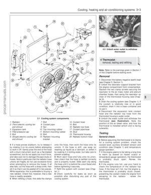 91
91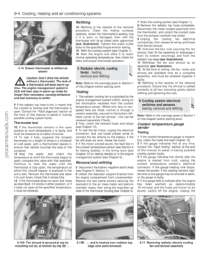 92
92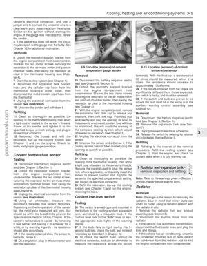 93
93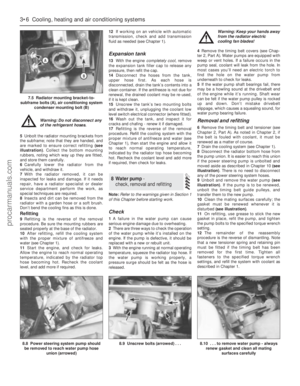 94
94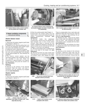 95
95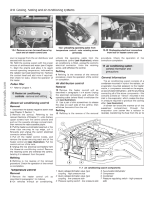 96
96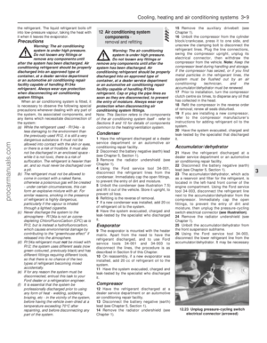 97
97 98
98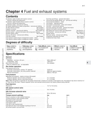 99
99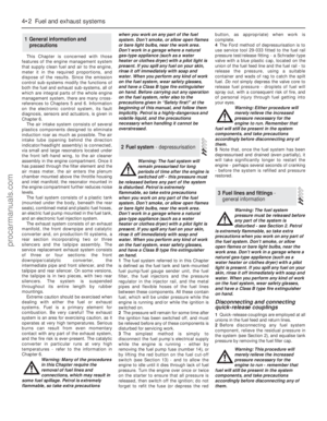 100
100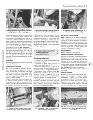 101
101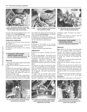 102
102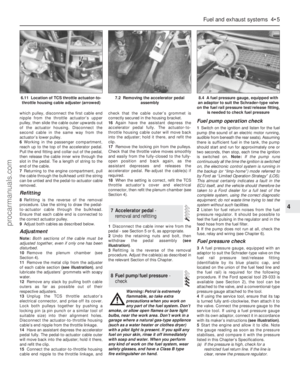 103
103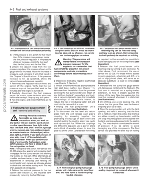 104
104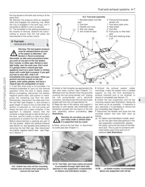 105
105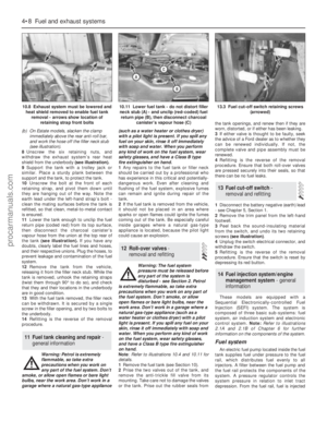 106
106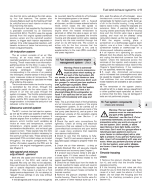 107
107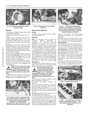 108
108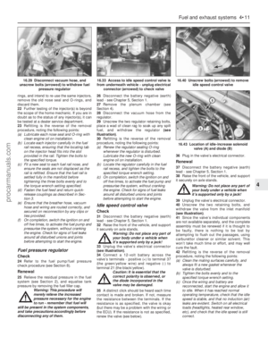 109
109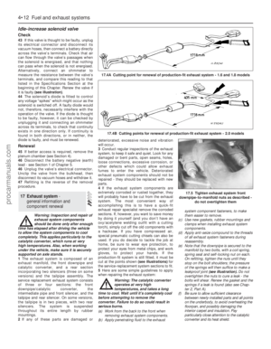 110
110 111
111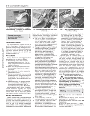 112
112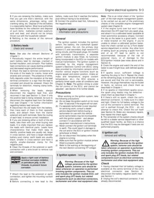 113
113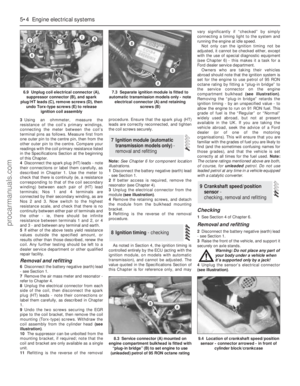 114
114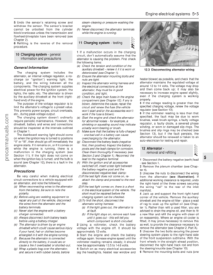 115
115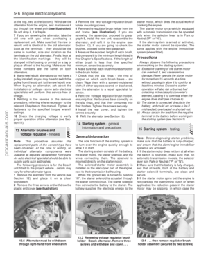 116
116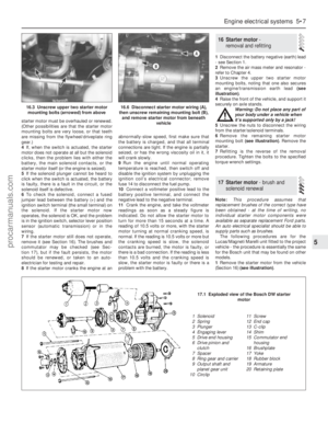 117
117 118
118 119
119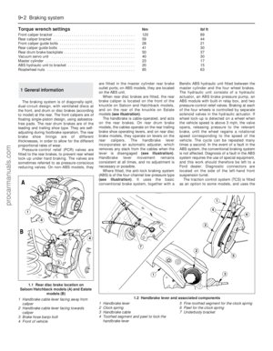 120
120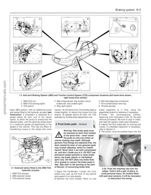 121
121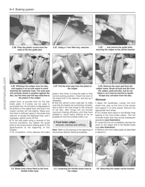 122
122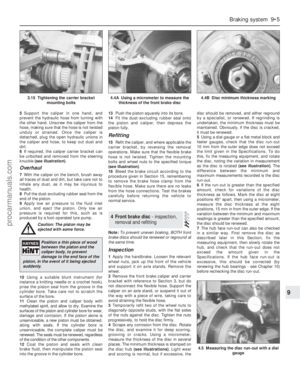 123
123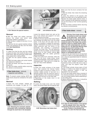 124
124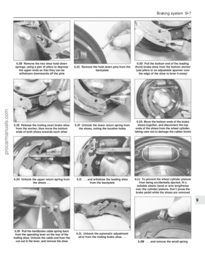 125
125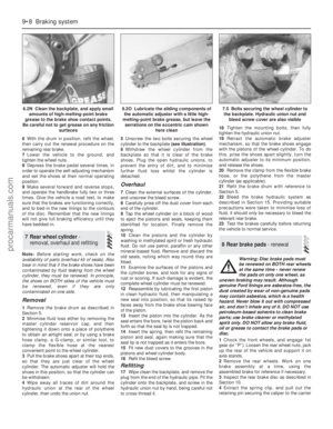 126
126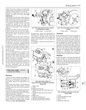 127
127 128
128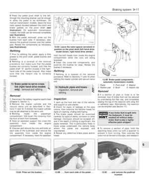 129
129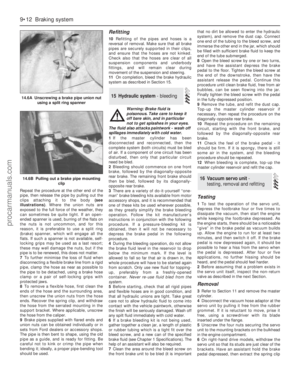 130
130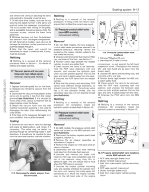 131
131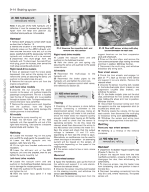 132
132 133
133 134
134 135
135 136
136 137
137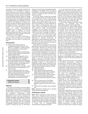 138
138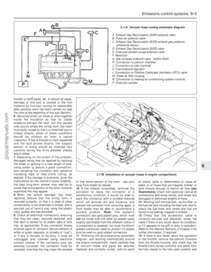 139
139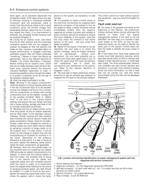 140
140 141
141 142
142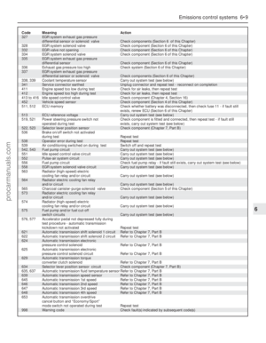 143
143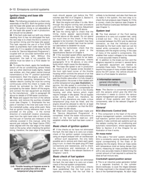 144
144 145
145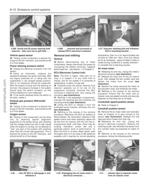 146
146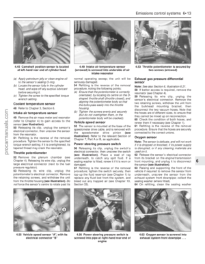 147
147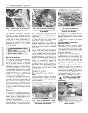 148
148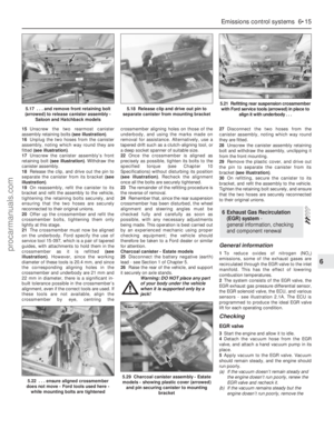 149
149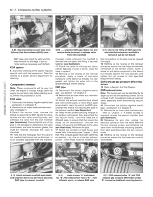 150
150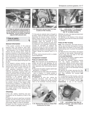 151
151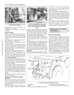 152
152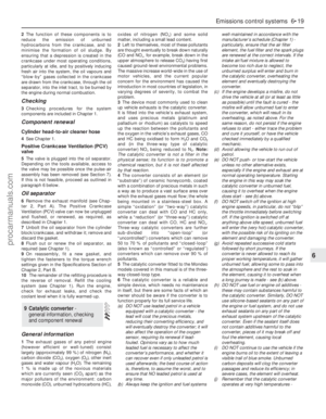 153
153 154
154 155
155 156
156 157
157 158
158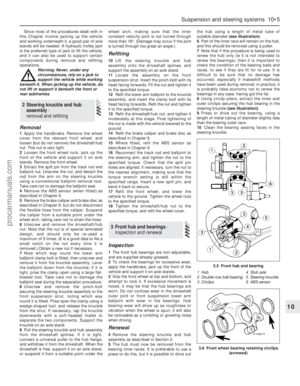 159
159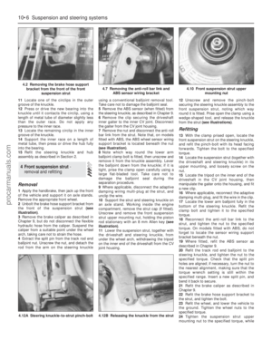 160
160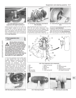 161
161 162
162 163
163 164
164 165
165 166
166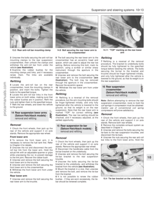 167
167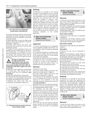 168
168 169
169 170
170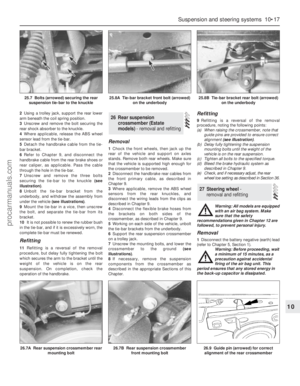 171
171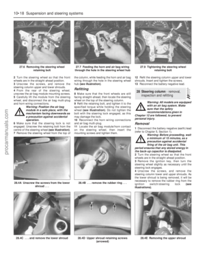 172
172 173
173 174
174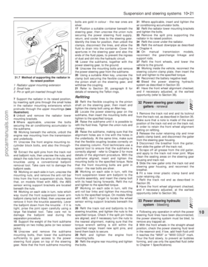 175
175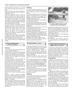 176
176 177
177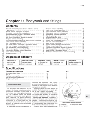 178
178 179
179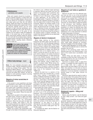 180
180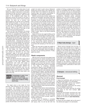 181
181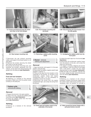 182
182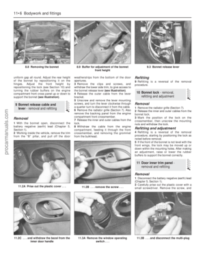 183
183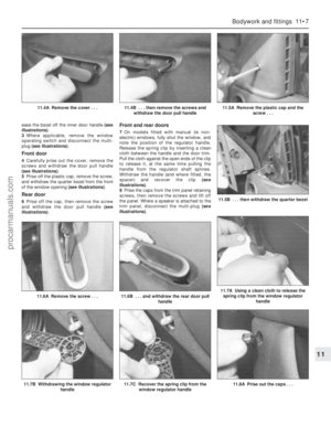 184
184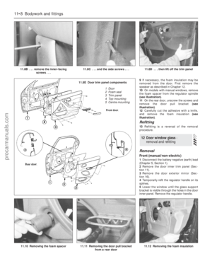 185
185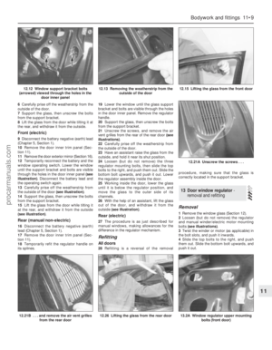 186
186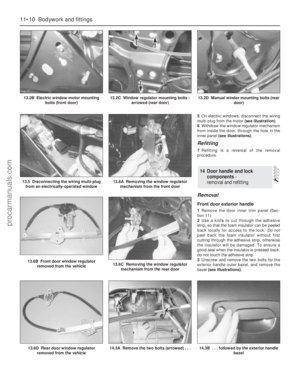 187
187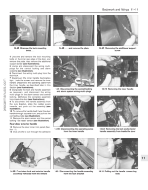 188
188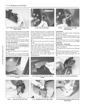 189
189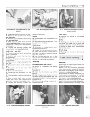 190
190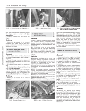 191
191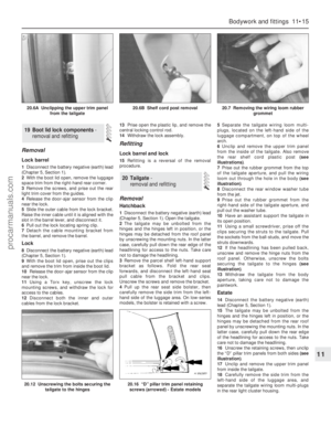 192
192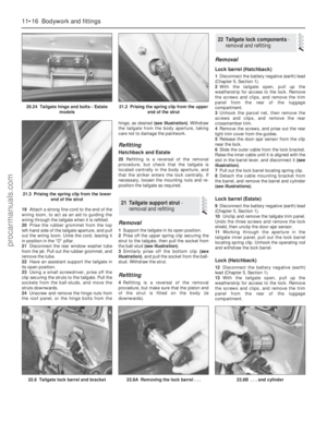 193
193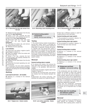 194
194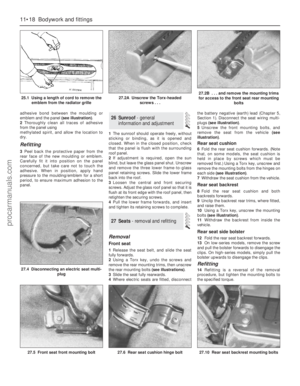 195
195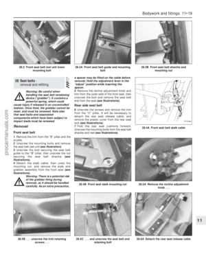 196
196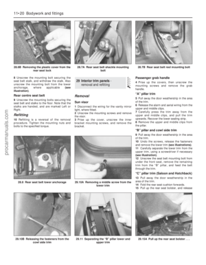 197
197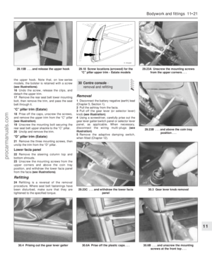 198
198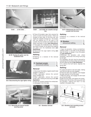 199
199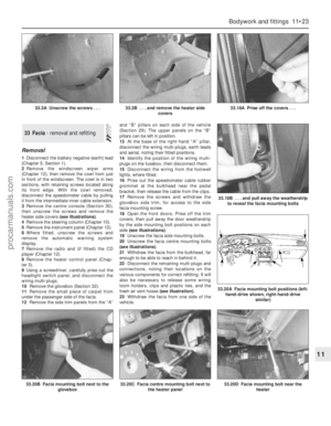 200
200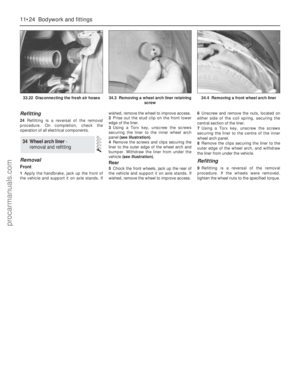 201
201 202
202 203
203 204
204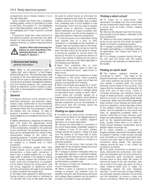 205
205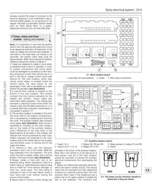 206
206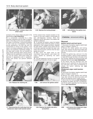 207
207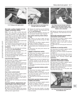 208
208 209
209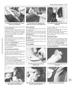 210
210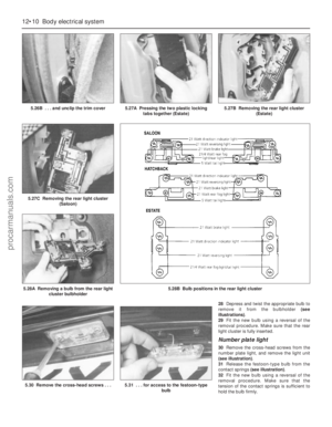 211
211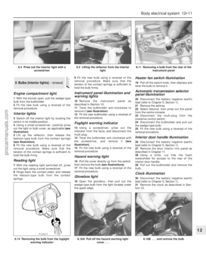 212
212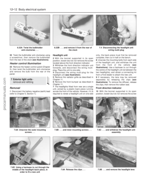 213
213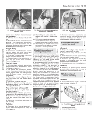 214
214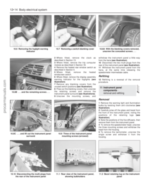 215
215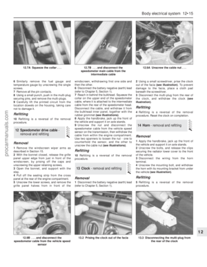 216
216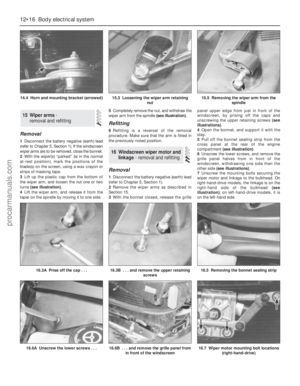 217
217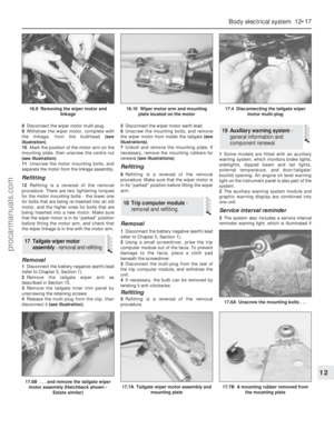 218
218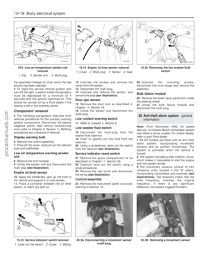 219
219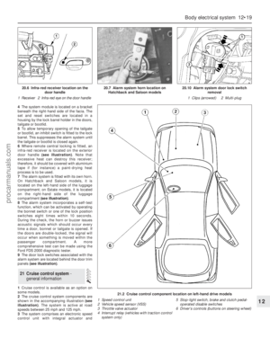 220
220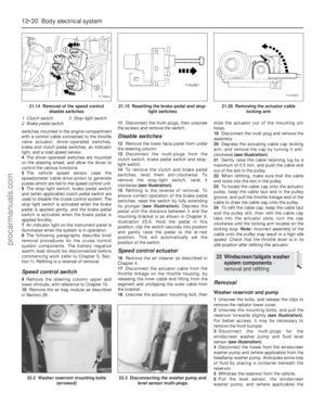 221
221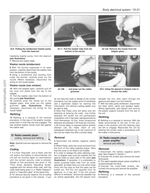 222
222 223
223 224
224 225
225 226
226 227
227 228
228 229
229 230
230 231
231 232
232 233
233 234
234 235
235 236
236 237
237 238
238 239
239 240
240 241
241 242
242 243
243 244
244 245
245 246
246 247
247 248
248 249
249 250
250 251
251 252
252 253
253 254
254 255
255 256
256 257
257 258
258 259
259 260
260 261
261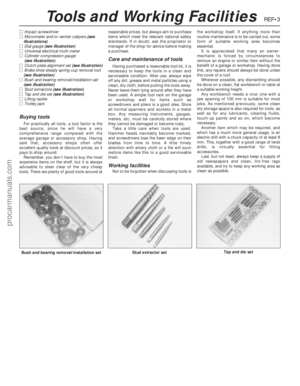 262
262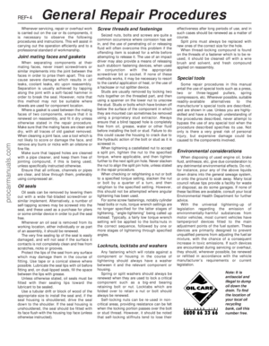 263
263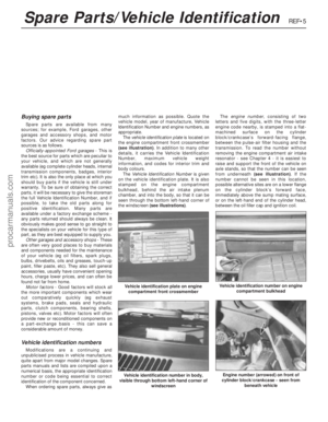 264
264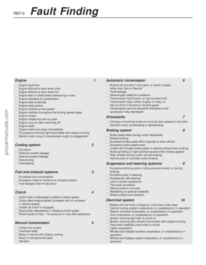 265
265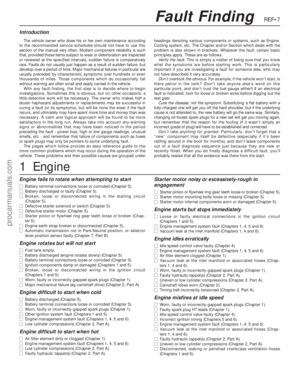 266
266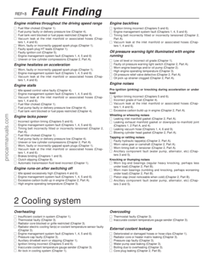 267
267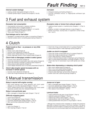 268
268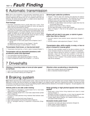 269
269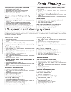 270
270 271
271 272
272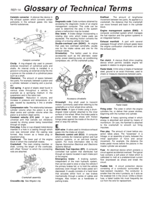 273
273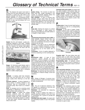 274
274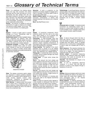 275
275 276
276 277
277 278
278