Page 89 of 279

Chapter 3
Cooling, heating, and air conditioning systems
Air conditioning system - general information
and precautions . . . . . . . . . . . . . . . . . . . . . . . . . . . . . . . . . . . . . . . . 11
Air conditioning system components - removal and refitting . . . . . . 12
Antifreeze - general information . . . . . . . . . . . . . . . . . . . . . . . . . . . . 2
Auxiliary drivebelt check and renewal . . . . . . . . . . . . . See Chapter 1
Coolant level check . . . . . . . . . . . . . . . . . . . . . . . . . . . See Chapter 1
Coolant renewal . . . . . . . . . . . . . . . . . . . . . . . . . . . . . . See Chapter 1
Cooling system checks (coolant leaks,
hose condition) . . . . . . . . . . . . . . . . . . . . . . . . . . . . . See Chapter 1
Cooling system electrical switches and sensors -
testing, removal and refitting . . . . . . . . . . . . . . . . . . . . . . . . . . . . . 6
Cooling system hoses - disconnection and renewal . . . . . . . . . . . . 3Cooling system servicing (draining, flushing
and refilling) . . . . . . . . . . . . . . . . . . . . . . . . . . . . . . . See Chapter 1
General information . . . . . . . . . . . . . . . . . . . . . . . . . . . . . . . . . . . . . . 1
Heater/air conditioning controls - removal and refitting . . . . . . . . . . 10
Heater/ventilation components - removal and refitting . . . . . . . . . . . 9
Pollen filter renewal . . . . . . . . . . . . . . . . . . . . . . . . . . . See Chapter 1
Radiator and expansion tank - removal, inspection
and refitting . . . . . . . . . . . . . . . . . . . . . . . . . . . . . . . . . . . . . . . . . . . . 7
Radiator electric cooling fan(s) - testing, removal and refitting . . . . . 5
Thermostat - removal, testing and refitting . . . . . . . . . . . . . . . . . . . . 4
Water pump - check, removal and refitting . . . . . . . . . . . . . . . . . . . . 8
Coolant
Mixture type . . . . . . . . . . . . . . . . . . . . . . . . . . . . . . . . . . . . . . . . . . . . . . See Chapter 1
Cooling system capacity . . . . . . . . . . . . . . . . . . . . . . . . . . . . . . . . . . . . . See Chapter 1
System pressure
Pressure test . . . . . . . . . . . . . . . . . . . . . . . . . . . . . . . . . . . . . . . . . . . . . . 1.2 bars - should hold this pressure for at least 10 seconds
Expansion tank filler cap
Pressure rating . . . . . . . . . . . . . . . . . . . . . . . . . . . . . . . . . . . . . . . . . . . . 1.2 bars approximately - see cap for actual value
Thermostat
Starts to open . . . . . . . . . . . . . . . . . . . . . . . . . . . . . . . . . . . . . . . . . . . . . 88°C
Radiator electric cooling fan
Switches on at:
Single-speed fans, two-speed fans - first stage . . . . . . . . . . . . . . . . . 100°C
Two-speed fans - second stage . . . . . . . . . . . . . . . . . . . . . . . . . . . . . 103°C
Switches off at:
Single-speed fans, two-speed fans - first stage . . . . . . . . . . . . . . . . . 93°C
Two-speed fans - second stage . . . . . . . . . . . . . . . . . . . . . . . . . . . . . 100°C
Coolant temperature sensor
Resistance:
At -40°C . . . . . . . . . . . . . . . . . . . . . . . . . . . . . . . . . . . . . . . . . . . . . . . . 860.0 to 900.0 kilohms
At 20°C . . . . . . . . . . . . . . . . . . . . . . . . . . . . . . . . . . . . . . . . . . . . . . . . 35.0 to 40.0 kilohms
At 100°C . . . . . . . . . . . . . . . . . . . . . . . . . . . . . . . . . . . . . . . . . . . . . . . 1.9 to 2.5 kilohms
At 120°C . . . . . . . . . . . . . . . . . . . . . . . . . . . . . . . . . . . . . . . . . . . . . . . 1.0 to 1.3 kilohms
Air conditioning system
Refrigerant . . . . . . . . . . . . . . . . . . . . . . . . . . . . . . . . . . . . . . . . . . . . . . . . R134a
3•1
Easy,suitable for
novice with little
experienceFairly easy,suitable
for beginner with
some experienceFairly difficult,suitable
for competent DIY
mechanicDifficult,suitable for
experienced DIY
mechanicVery difficult,
suitable for expert DIY
or professional
Degrees of difficulty
Specifications Contents
3
procarmanuals.com
Page 90 of 279

Torque wrench settingsNm lbf ft
Radiator mounting bracket-to-subframe bolts . . . . . . . . . . . . . . . . . . . . 23 17
Fluid cooler pipe unions - automatic transmission . . . . . . . . . . . . . . . . . 23 17
Thermostat housing-to-cylinder head bolts . . . . . . . . . . . . . . . . . . . . . . 20 15
Water outlet-to-thermostat housing bolts . . . . . . . . . . . . . . . . . . . . . . . 8 to 11 6 to 8
Coolant temperature sensor . . . . . . . . . . . . . . . . . . . . . . . . . . . . . . . . . . 23 17
Coolant temperature gauge sender . . . . . . . . . . . . . . . . . . . . . . . . . . . . 8 6
Water pump bolts . . . . . . . . . . . . . . . . . . . . . . . . . . . . . . . . . . . . . . . . . . 18 13
Water pump pulley bolts . . . . . . . . . . . . . . . . . . . . . . . . . . . . . . . . . . . . . See Chapter 2A
Air conditioning compressor mounting bolts . . . . . . . . . . . . . . . . . . . . . 25 18
3•2 Cooling, heating and air conditioning systems
Engine cooling system
All vehicles covered by this manual employ
a pressurised engine cooling system with
thermostatically-controlled coolant circu-
lation. A water pump mounted on the drivebelt
end of the cylinder block/crankcase pumps
coolant through the engine. The coolant flows
around each cylinder and toward the
transmission end of the engine. Cast-in
coolant passages direct coolant around the
inlet and exhaust ports, near the spark
plug areas and close to the exhaust valve
guides.
A wax pellet type thermostat is located in a
housing at the transmission end of the engine.
During warm-up, the closed thermostat
prevents coolant from circulating through the
radiator. Instead, it returns through the
coolant metal pipe running across the front of
the engine to the radiator bottom hose and
the water pump. The supply to the heater is
made from the rear of the thermostat housing.
As the engine nears normal operating
temperature, the thermostat opens and allows
hot coolant to travel through the radiator,
where it is cooled before returning to the
engine.
The cooling system is sealed by a pressure-
type filler cap in the expansion tank. The
pressure in the system raises the boiling point
of the coolant, and increases the cooling
efficiency of the radiator. When the engine is
at normal operating temperature, the coolant
expands, and the surplus is displaced into the
expansion tank. When the system cools, the
surplus coolant is automatically drawn back
from the tank into the radiator.
Warning: DO NOT attempt to
remove the expansion tank filler
cap, or to disturb any part of the
cooling system, while it or the
engine is hot, as there is a very great risk
of scalding. If the expansion tank filler cap
must be removed before the engine and
radiator have fully cooled down (even
though this is not recommended) the
pressure in the cooling system must first
be released. Cover the cap with a thick
layer of cloth, to avoid scalding, and slowly
unscrew the filler cap until a hissing sound
can be heard. When the hissing hasstopped, showing that pressure is
released, slowly unscrew the filler cap
further until it can be removed; if more
hissing sounds are heard, wait until they
have stopped before unscrewing the cap
completely. At all times, keep well away
from the filler opening.
Warning: Do not allow antifreeze
to come in contact with your
skin, or with the painted surfaces
of the vehicle. Rinse off spills
immediately with plenty of water. Never
leave antifreeze lying around in an open
container, or in a puddle in the driveway or
on the garage floor. Children and pets are
attracted by its sweet smell, but antifreeze
is fatal if ingested.
Warning: If the engine is hot, the
electric cooling fan may start
rotating even if the engine is not
running, so be careful to keep
hands, hair and loose clothing well clear
when working in the engine compartment.
Heating system
The heating system consists of a blower fan
and heater matrix (radiator) located in the
heater unit, with hoses connecting the heater
matrix to the engine cooling system. Hot
engine coolant is circulated through the
heater matrix. When the heater temperature
control on the facia is operated, a flap door
opens to expose the heater box to the
passenger compartment. When the blower
control is operated, the blower fan forces air
through the unit according to the setting
selected.
Air conditioning system
See Section 11.
Warning: Do not allow antifreeze to come in
contact with your skin, or with the painted
surfaces of the vehicle. Rinse off spills
immediately with plenty of water. Antifreeze is
highly toxic if ingested. Never leave antifreeze
lying around in an open container, or in
puddles on the floor; children and pets are
attracted by its sweet smell, and may drink it.
Check with local authorities about disposing
of used antifreeze - many have collection
centres which will see that antifreeze is
disposed of safely.The cooling system should be filled with a
water/ethylene glycol-based antifreeze
solution, of a strength which will prevent
freezing down to at least -25°C, or lower if the
local climate requires it. Antifreeze also
provides protection against corrosion, and
increases the coolant boiling point.
The cooling system should be maintained
according to the schedule described in
Chapter 1. If antifreeze is used that is not to
Ford’s specification, old or contaminated
coolant mixtures are likely to cause damage,
and encourage the formation of corrosion and
scale in the system. Use distilled water with
the antifreeze, if available - if not, be sure to
use only soft water. Clean rainwater is
suitable.
Before adding antifreeze, check all hoses
and hose connections, because antifreeze
tends to leak through very small openings.
Engines don’t normally consume coolant, so if
the level goes down, find the cause and
correct it.
The exact mixture of antifreeze-to-water
which you should use depends on the
relative weather conditions. The mixture
should contain at least 40% antifreeze, but
not more than 70%. Consult the mixture
ratio chart on the antifreeze container
before adding coolant. Hydrometers are
available at most automotive accessory
shops to test the coolant. Use antifreeze
which meets the vehicle manufacturer’s
specifications.
Note:Refer to the warnings given in Section 1
of this Chapter before starting work.
1If the checks described in Chapter 1 reveal
a faulty hose, it must be renewed as follows
(see illustration).
2First drain the cooling system (see Chap-
ter 1); if the antifreeze is not due for renewal,
the drained coolant may be re-used, if it is
collected in a clean container.
3To disconnect any hose, use a pair of pliers
to release the spring clamps (or a screwdriver
to slacken screw-type clamps), then move
them along the hose clear of the union.
Carefully work the hose off its stubs. The
hoses can be removed with relative ease
when new - on an older car, they may have
stuck.
3 Cooling system hoses -
disconnection and renewal
2 Antifreeze - general information
1 General information
procarmanuals.com
Page 91 of 279

4If a hose proves stubborn, try to release it
by rotating it on its unions before attempting
to work it off. Gently prise the end of the hose
with a blunt instrument (such as a flat-bladed
screwdriver), but do not apply too much force,
and take care not to damage the pipe stubs or
hoses. Note in particular that the radiator hose
unions are fragile; do not use excessive force
when attempting to remove the hoses. If all
else fails, cut the hose with a sharp knife, then
slit it so that it can be peeled off in two pieces.
While expensive, this is preferable to buying a
new radiator. Check first, however, that a new
hose is readily available.
5When refitting a hose, first slide the clampsonto the hose, then work the hose onto its
unions. If the hose is stiff, use soap (or
washing-up liquid) as a lubricant, or soften it
by soaking it in boiling water, but take care to
prevent scalding.
6Work each hose end fully onto its union,
then check that the hose is settled correctly
and is properly routed. Slide each clip along
the hose until it is behind the union flared end,
before tightening it securely.
7Refill the system with coolant (see Chap-
ter 1).
8Check carefully for leaks as soon as
possible after disturbing any part of the
cooling system.Note:Refer to the warnings given in Section 1
of this Chapter before starting work.
Removal
1Disconnect the battery negative (earth) lead
(see Chapter 5, Section 1).
2Unbolt the resonator support bracket from
the engine compartment front crossmember.
Slacken the two clamp screws securing the
resonator to the air mass meter and plenum
chamber hoses, then swing the resonator up
clear of the thermostat housing (see Chap-
ter 4).
3Drain the cooling system (see Chapter 1). If
the coolant is relatively new or in good
condition, drain it into a clean container and
re-use it.
4Disconnect the expansion tank coolant
hose and the radiator top hose from the
thermostat housing’s water outlet.
5Unbolt the water outlet and withdraw the
thermostat (see illustration). Note the
position of the air bleed valve, and how the
thermostat is installed (which end is facing
outwards).
Testing
General check
6Before assuming the thermostat is to blame
for a cooling system problem, check the
coolant level, auxiliary drivebelt tension and
condition (see Chapter 1) and temperature
gauge operation.
7If the engine seems to be taking a long time
to warm up (based on heater output or
temperature gauge operation), the thermostat
is probably stuck open. Renew the
thermostat.
8If the engine runs hot, use your hand to
check the temperature of the radiator top
hose. If the hose isn’t hot, but the engine is,
the thermostat is probably stuck closed,
preventing the coolant inside the engine from
escaping to the radiator - renew the
thermostat.
4 Thermostat -
removal, testing and refitting
Cooling, heating and air conditioning systems 3•3
3
4.5 Unbolt water outlet to withdraw
thermostat
3.1 Cooling system components
1 Radiator
2 (Twin) electric cooling fan
and shroud
3 Expansion tank
4 Filler/pressure cap
5 Bolt
6 (Single) electric cooling fan
and shroud7 Bolt
8 Coolant pipe
9 Nut
10 Top mounting rubber
11 Bottom mounting rubber
12 Bolt
13 Radiator mounting
bracket14 Coolant hose
15 Bolt
16 Radiator top hose
17 Coolant pipe/hose
18 Stud
19 Thermostat housing
20 Radiator bottom hose
procarmanuals.com
Page 92 of 279

Caution: Don’t drive the vehicle
without a thermostat. The lack of
a thermostat will slow warm-up
time. The engine management system’s
ECU will then stay in warm-up mode for
longer than necessary, causing emissions
and fuel economy to suffer.
9If the radiator top hose is hot, it means that
the coolant is flowing and the thermostat is
open. Consult the “Fault diagnosis”section at
the front of this manual to assist in tracing
possible cooling system faults.
Thermostat test
10If the thermostat remains in the open
position at room temperature, it is faulty, and
must be renewed as a matter of course.
11To test it fully, suspend the (closed)
thermostat on a length of string in a container
of cold water, with a thermometer beside it;
ensure that neither touches the side of the
container.
12Heat the water, and check the
temperature at which the thermostat begins to
open; compare this value with that specified.
Continue to heat the water until the
thermostat is fully open; the temperature at
which this should happen is stamped in the
unit’s end. Remove the thermostat and allow
it to cool down; check that it closes fully.
13If the thermostat does not open and close
as described, if it sticks in either position, or if
it does not open at the specified temperature,
it must be renewed.
Refitting
14Refitting is the reverse of the removal
procedure. Clean the mating surfaces
carefully, renew the thermostat’s sealing ring
if it is worn or damaged, then refit the
thermostat with its air bleed valve uppermost
(see illustration). Tighten the water outlet
bolts to the specified torque wrench setting.
15Refill the cooling system (see Chapter 1).
16Start the engine and allow it to reach
normal operating temperature, then check for
leaks and proper thermostat operation.
Note:Refer to the warnings given in Section 1
of this Chapter before starting work.
Testing
1The radiator cooling fan is controlled by the
engine management system’s ECU, acting on
the information received from the coolant
temperature sensor. Where twin fans or two-
speed fans are fitted, control is through a
resistor assembly, secured to the bottom left-
hand corner of the fan shroud - this can be
renewed separately if faulty.
2First, check the relevant fuses and relays
(see Chapter 12).
3To test the fan motor, unplug the electrical
connector, and use fused jumper wires to
connect the fan directly to the battery. If the
fan still does not work, renew the motor.
4If the motor proved sound, the fault lies in
the coolant temperature sensor (see Section 6
for testing details), in the wiring loom (see
Chapter 12 for testing details) or in the engine
management system (see Chapter 6).
Removal and refitting
5Disconnect the battery negative (earth) lead
(see Chapter 5, Section 1).
6Unbolt the resonator support bracket from
the engine compartment front crossmember.
Slacken the two clamp screws securing the
resonator to the air mass meter and plenum
chamber hoses, then swing the resonator up
clear of the thermostat housing (see Chapter 4).7Drain the cooling system (see Chapter 1).
8Remove the radiator top hose completely.
Disconnect the metal coolant pipe/hose from
the thermostat, and unbolt the coolant pipe
from the exhaust manifold heat shield.
9Unplug the cooling fan electrical
connector(s), then release all wiring and hoses
from the fan shroud.
10Unscrew the two nuts securing the fan
shroud, then lift the assembly to disengage it
from its bottom mountings and from the
radiator top edge (see illustrations).
11Withdraw the fan and shroud as an
assembly (see illustration).
12At the time of writing, the fan, motor and
shroud are available only as a complete
assembly, and must be renewed together if
faulty.
13Refitting is the reverse of the removal
procedure. Ensure that the shroud is settled
correctly at all four mounting points before
refitting and tightening the nuts.
Note:Refer to the warnings given in Section 1
of this Chapter before starting work.
Coolant temperature gauge
sender
Testing
1If the coolant temperature gauge is inopera-
tive, check the fuses first (see Chapter 12).
2If the gauge indicates Hot at any time,
consult the “Fault finding”section at the end
of this manual, to assist in tracing possible
cooling system faults.
3If the gauge indicates Hot shortly after the
engine is started from cold, unplug the
coolant temperature sender’s electrical
connector. If the gauge reading now drops,
renew the sender. If the reading remains high,
the wire to the gauge may be shorted to earth,
or the gauge is faulty.
4If the gauge fails to indicate after the engine
has been warmed up (approximately
10 minutes) and the fuses are known to be
sound, switch off the engine. Unplug the
6 Cooling system electrical
switches and sensors-
testing, removal and refitting
5 Radiator electric cooling
fan(s)- testing,
removal and refitting
3•4 Cooling, heating and air conditioning systems
4.14 Ensure thermostat is refitted as
shown
5.10A Fan shroud is secured at top by
mounting nut (A), at bottom by clip (B) . . .5.10B . . . and is hooked over radiator top
edge (one point arrowed)5.11 Removing radiator electric cooling
fan and shroud assembly
procarmanuals.com
Page 93 of 279
 on the engine.
Switch on the ignition without starting the
engine. If the gauge")
sender’s electrical connector, and use a
jumper wire to connect the white/red wire to a
clean earth point (bare metal) on the engine.
Switch on the ignition without starting the
engine. If the gauge now indicates Hot, renew
the sender.
5If the gauge still does not work, the circuit
may be open, or the gauge may be faulty. See
Chapter 12 for additional information.
Removal
6Unbolt the resonator support bracket from
the engine compartment front crossmember.
Slacken the two clamp screws securing the
resonator to the air mass meter and plenum
chamber hoses, then swing the resonator up
clear of the thermostat housing (see Chap-
ter 4).
7Drain the cooling system (see Chapter 1).
8Disconnect the expansion tank coolant
hose and the radiator top hose from the
thermostat housing’s water outlet, then
disconnect the metal coolant pipe/hose from
the thermostat.
9Unplug the electrical connector from the
sender (see illustration).
10Unscrew the sender and withdraw it.
Refitting
11Clean as thoroughly as possible the
opening in the thermostat housing, then apply
a light coat of sealant to the sender’s threads.
Screw in the sender and tighten it to the
specified torque wrench setting, and plug in
its electrical connector.
12Reconnect the hoses and refit the
resonator, top-up the cooling system (see
Chapter 1) and run the engine. Check for
leaks and proper gauge operation.
Coolant temperature sensor
Testing
13Disconnect the battery negative (earth)
lead (see Chapter 5, Section 1).
14Unbolt the resonator support bracket
from the engine compartment front
crossmember. Slacken the two clamp screws
securing the resonator to the air mass meter
and plenum chamber hoses, then swing the
resonator up clear of the thermostat housing
(see Chapter 4).
15Unplug the electrical connector from the
sensor (see illustration).
16Using an ohmmeter, measure the
resistance between the sensor terminals.
Depending on the temperature of the sensor
tip, the resistance measured will vary, but
should be within the broad limits given in the
Specifications Section of this Chapter. If the
sensor’s temperature is varied - by removing
it (see below) and placing it in a freezer for a
while, or by warming it gently - its resistance
should alter accordingly.
17If the results obtained show the sensor to
be faulty, renew it.
18On completion, plug in the connector and
refit the resonator.
Removal
19Disconnect the battery negative (earth)
lead (see Chapter 5, Section 1).
20Unbolt the resonator support bracket
from the engine compartment front
crossmember. Slacken the two clamp screws
securing the resonator to the air mass meter
and plenum chamber hoses, then swing the
resonator up clear of the thermostat housing
(see Chapter 4).
21With the engine completely cool, remove
the expansion tank filler cap to release any
pressure, then refit the cap. Provided you
work swiftly and plug the opening as soon as
the sensor is unscrewed, coolant loss will thus
be minimised; this will avoid the draining of
the complete cooling system which would
otherwise be necessary (see Chapter 1).
22Unplug the electrical connector from the
sensor.
23Unscrew the sensor and withdraw it. If the
cooling system has not been drained, plug the
opening as quickly as possible.
Refitting
24Clean as thoroughly as possible the
opening in the thermostat housing, then apply
a light coat of sealant to the sensor’s threads.
Remove the material used to plug the sensor
hole (where applicable), and quickly install the
sensor to prevent coolant loss. Tighten the
sensor to the specified torque wrench setting,
and plug in its electrical connector.
25Refit the resonator, top-up the cooling
system (see Chapter 1) and run the engine,
checking for leaks.
Coolant low level switch
Testing
26The switch is a reed-type unit mounted in
the bottom of the cooling system expansion
tank, activated by a magnetic float. If the
coolant level falls to the “MIN” level or less,
the appropriate bulb lights in the warning
display.
27If the bulb fails to light during the 5-
second bulb test, check the bulb, and renew if
necessary as described in Chapter 12.
28To check the switch itself, unplug its
electrical connector, and use an ohmmeter to
measure the resistance across the switchterminals. With the float up, a resistance of
90 ohms should be measured; when it is
down, the resistance should increase to
approximately 150 kilohms.
29If the results obtained from the check are
significantly different from those expected,
the switch is faulty, and must be renewed.
30If the switch and bulb are proven to be
sound, the fault must be in the wiring or in the
auxiliary warning control assembly (see
Chapter 12).
Removal
31Disconnect the battery negative (earth)
lead (see Chapter 5, Section 1).
32Remove the expansion tank (see Sec-
tion 7).
33Unplug the switch electrical connector.
34Release the switch by twisting its retainer
anti-clockwise, then withdraw it.
Refitting
35Refitting is the reverse of the removal
procedure. Refill the cooling system (see
Chapter 1). Start the engine, and check for
coolant leaks when it is fully warmed-up.
Note:Refer to the warnings given in Section 1
of this Chapter before starting work.
Radiator
Removal
Note:If leakage is the reason for removing the
radiator, bear in mind that minor leaks can
often be cured using a radiator sealant with
the radiator in situ.
1Remove the radiator fan and shroud
assembly (see Section 5).
2Disconnect the bottom hose from the
radiator.
3If the vehicle has automatic transmission,
disconnect the fluid cooler lines, and plug the
lines and fittings.
4If the vehicle has air conditioning, unscrew
the condenser mounting nuts or bolts, detach
the condenser from the radiator, and tie it to
the engine compartment front crossmember.
7 Radiator and expansion tank -
removal, inspection and refitting
Cooling, heating and air conditioning systems 3•5
3
6.9 Location (arrowed) of coolant
temperature gauge sender6.15 Location (arrowed) of coolant
temperature sensor
procarmanuals.com
Page 94 of 279

Warning: Do not disconnect any
of the refrigerant hoses.
5Unbolt the radiator mounting brackets from
the subframe; note that they are handed, and
are marked to ensure correct refitting (see
illustration). Collect the bottom mounting
rubbers, noting which way up they are fitted,
and store them carefully.
6Carefully lower the radiator from the
vehicle, and withdraw it.
7With the radiator removed, it can be
inspected for leaks and damage. If it needs
repair, have a radiator specialist or dealer
service department perform the work, as
special techniques are required.
8Insects and dirt can be removed from the
radiator with a garden hose or a soft brush.
Don’t bend the cooling fins as this is done.
Refitting
9Refitting is the reverse of the removal
procedure. Be sure the mounting rubbers are
seated properly at the base of the radiator.
10After refitting, refill the cooling system
with the proper mixture of antifreeze and
water (see Chapter 1).
11Start the engine, and check for leaks.
Allow the engine to reach normal operating
temperature, indicated by the radiator top
hose becoming hot. Recheck the coolant
level, and add more if required.12If working on an vehicle with automatic
transmission, check and add transmission
fluid as needed (see Chapter 1).
Expansion tank
13With the engine completely cool, remove
the expansion tank filler cap to release any
pressure, then refit the cap.
14Disconnect the hoses from the tank,
upper hose first. As each hose is
disconnected, drain the tank’s contents into a
clean container. If the antifreeze is not due for
renewal, the drained coolant may be re-used,
if it is kept clean.
15Unscrew the tank’s two mounting bolts
and withdraw it, unplugging the coolant low
level switch electrical connector (where fitted).
16Wash out the tank, and inspect it for
cracks and chafing - renew it if damaged.
17Refitting is the reverse of the removal
procedure. Refill the cooling system with the
proper mixture of antifreeze and water (see
Chapter 1), then start the engine and allow it
to reach normal operating temperature,
indicated by the radiator top hose becoming
hot. Recheck the coolant level and add more
if required, then check for leaks.
Note:Refer to the warnings given in Section 1
of this Chapter before starting work.
Check
1A failure in the water pump can cause
serious engine damage due to overheating.
2There are three ways to check the operation
of the water pump while it’s installed on the
engine. If the pump is defective, it should be
replaced with a new or rebuilt unit.
3With the engine running at normal operating
temperature, squeeze the radiator top hose. If
the water pump is working properly, a
pressure surge should be felt as the hose is
released. Warning: Keep your hands away
from the radiator electric
cooling fan blades!
4Remove the timing belt covers (see Chap-
ter 2, Part A). Water pumps are equipped with
weep or vent holes. If a failure occurs in the
pump seal, coolant will leak from the hole. In
most cases you’ll need an electric torch to
find the hole on the water pump from
underneath to check for leaks.
5If the water pump shaft bearings fail, there
may be a howling sound at the drivebelt end
of the engine while it’s running. Shaft wear
can be felt if the water pump pulley is rocked
up and down. Don’t mistake drivebelt
slippage, which causes a squealing sound, for
water pump bearing failure.
Removal and refitting
6Remove the timing belt and tensioner (see
Chapter 2, Part A). As noted in Chapter 2, if
the belt is fouled with coolant, it must be
renewed as a matter of course.
7Drain the cooling system (see Chapter 1).
8Disconnect the radiator bottom hose from
the pump union. It is easier to reach this union
if the power steering pump is unbolted and
moved aside as described in Chapter 10 (see
illustration). There is no need to disconnect
any of the power steering system hoses.
9Unbolt and remove the water pump (see
illustration). If the pump is to be renewed,
unbolt the timing belt guide pulleys, and
transfer them to the new pump.
10Clean the mating surfaces carefully; the
gasket must be renewed whenever it is
disturbed (see illustration).
11On refitting, use grease to stick the new
gasket in place, refit the pump, and tighten
the pump bolts to the specified torque wrench
setting.
12The remainder of the reassembly
procedure is the reverse of dismantling. Note
that a new tensioner spring and retaining pin
must be fitted if the timing belt has been
removed for the first time. Tighten all
fasteners to the specified torque wrench
settings, and refill the system with coolant as
described in Chapter 1.
8 Water pump -
check, removal and refitting
3•6 Cooling, heating and air conditioning systems
7.5 Radiator mounting bracket-to-
subframe bolts (A), air conditioning system
condenser mounting bolt (B)
8.8 Power steering system pump should
be removed to reach water pump hose
union (arrowed)8.9 Unscrew bolts (arrowed) . . .8.10 . . . to remove water pump - always
renew gasket and clean all mating
surfaces carefully
procarmanuals.com
Page 95 of 279
 lead
(see Chapter 5, Section 1).
2Release the four clips (by pulling them out)
securing the passenger side footwell upper
trim pane")
Heater blower motor
Removal
1Disconnect the battery negative (earth) lead
(see Chapter 5, Section 1).
2Release the four clips (by pulling them out)
securing the passenger side footwell upper
trim panel, then withdraw the panel.
3Unplug the motor’s electrical connector.
4Lift the motor’s retaining lug slightly, twist
the motor anti-clockwise (seen from beneath)
through approximately 30°, then withdraw the
assembly.
5The motor’s control resistor can be
removed by sliding a slim screwdriver into the
slot provided in one end. Press the
screwdriver in approximately 5 mm against
spring pressure, and prise the resistor out
(see illustration).
Refitting
6Refitting is the reverse of the removal
procedure. Refit the motor, and twist it
clockwise until the retaining lug engages
securely (see illustration).
Heater matrix
Removal
7Disconnect the battery negative (earth) lead
(see Chapter 5, Section 1).8Drain the cooling system (see Chapter 1).
9Disconnect the coolant hoses from the
heater matrix unions protruding through the
engine compartment bulkhead (see
illustrations).
10Working inside the passenger
compartment, remove the trim panels from
each footwell, just in front of the centre
console. Each panel is secured by two
screws. If additional clearance is required, the
centre console can be removed as well (see
Chapter 11), but this is not essential.
11Remove the single screw to release the air
duct in the base of the heater unit (see
illustration).
12Remove the three Torx-type screws (size
T20) securing the air distributor to the heater
unit bottom cover, then release the clips.There is a single plastic clip on each side, and
additional metal clips may be found. Push the
duct up to retract it, and withdraw the air
distributor (see illustration).
13Release the clips - there are two plastic
clips on each side, and additional metal clips
may be found - then withdraw the heater
unit’s bottom cover, complete with the matrix
(see illustration).
14Undo the screw and withdraw the clamp
to separate the matrix from the bottom cover
(see illustration).
Refitting
15Refitting is the reverse of the removal
procedure. Additional metal clips may be
required to secure the heater unit’s bottom
cover and the air distributor. Ensure that the
9 Heater/ventilation components
- removal and refitting
Cooling, heating and air conditioning systems 3•7
3
9.12 . . . release clips (A) to free air
distributor from base of heater unit - note
clips (B) securing . . .9.13 . . . heater unit’s bottom cover,
complete with matrix9.14 Remove clamp (one screw) to separate
matrix from heater unit’s bottom cover
9.5 Heater blower motor control resistor
can be prised out of heater unit9.6 Ensure blower motor retaining lug
(arrowed) engages securely in heater unit
on reassembly9.9A Coolant pipes to heater matrix must
be disconnected . . .
9.9B . . . but can be reached best from
beneath vehicle (arrowed)9.11 Remove screw to allow air duct to be
retracted into air distributor at base of
heater unit . . .
procarmanuals.com
Page 96 of 279
. Start the engine and allow it to reach")
duct is lowered from the air distributor and
secured with its screw.
16Refill the cooling system with the proper
mixture of antifreeze and water (see Chapter
1). Start the engine and allow it to reach
normal operating temperature, indicated by
the radiator top hose becoming hot. Recheck
the coolant level and add more if required,
then check for leaks. Check the operation of
the heater.
Pollen filter
17Refer to Chapter 1.
Blower/air conditioning control
Removal
1Disconnect the battery negative (earth) lead
(see Chapter 5, Section 1).
2Remove the ashtray. Referring to the
relevant Sections of Chapter 11, undo the two
upper screws from the centre console and
pull out the cassette storage compartment,
then remove the radio/cassette player.
3Pull the heater control/radio bezel out of the
three clips securing its top edge, pull it
forwards and unplug the switch electrical
connector (where fitted).
4Pull off the heater control knobs, and
remove the screw securing each end of the
heater control unit (see illustration). Pull the
control unit out of the facia.
5Unplug the two electrical connectors from
the blower/air conditioning control. Remove
the retaining screw and withdraw the control,
twisting it to release it from the panel.
Refitting
6Refitting is the reverse of the removal
procedure. Check the operation of the control
on completion.
Temperature control
Removal
7Remove the heater control unit as
described in paragraphs 1 to 4 above.
8On vehicles without air conditioning,unhook the operating cable from the
temperature control (see illustration); where
air conditioning is fitted, unplug the control’s
electrical connector. Undo the retaining
screw, and withdraw the control.
Refitting
9Refitting is the reverse of the removal
procedure; check the operation of the control
on completion.
Air distribution control
Removal
10Remove the heater control unit as
described in paragraphs 1 to 4 above. Unplug
the electrical connectors, and unhook the
operating cable (where fitted) to withdraw the
unit (see illustration).
11Use a pair of slim screwdrivers to release
the clips on each side of the control, then
withdraw the control from the unit.
Refitting
12Refitting is the reverse of the removalprocedure. Check the operation of the
controls on completion.
General information
The air conditioning system consists of a
condenser mounted in front of the radiator, an
evaporator mounted adjacent to the heater
matrix, a compressor mounted on the engine,
an accumulator/dehydrator, and the plumbing
connecting all of the above components - this
contains a choke (or “venturi”) mounted in the
inlet to the evaporator, which creates the drop
in pressure required to produce the cooling
effect (see illustration).
A blower fan forces the warmer air of the
passenger compartment through the
evaporator core (rather like a radiator in
reverse), transferring the heat from the air to
11 Air conditioning system -
general information and
precautions
10 Heater/air conditioning
controls- removal and refitting
3•8 Cooling, heating and air conditioning systems
10.4 Remove screws (arrowed) securing
each end of heater control unit10.8 Unhooking operating cable from
temperature control - note retaining screw
(arrowed)10.10 Unplugging electrical connectors
from rear of heater control unit
11.1 Air conditioning system components
1 Quick-release Schrader valve-type
coupling - high-pressure side
2 Quick-release Schrader valve-type
coupling - low-pressure side
3 Pressure-cycling switch - low-pressure side4 Accumulator/dehydrator
5 Compressor
6 Condenser
7 Pressure-regulating switch - high-pressure
side
procarmanuals.com
 1
1 2
2 3
3 4
4 5
5 6
6 7
7 8
8 9
9 10
10 11
11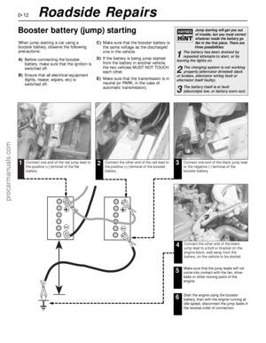 12
12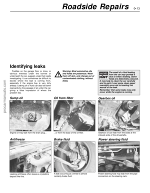 13
13 14
14 15
15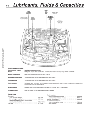 16
16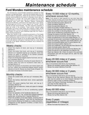 17
17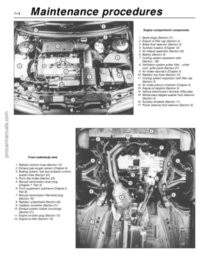 18
18 19
19 20
20 21
21 22
22 23
23 24
24 25
25 26
26 27
27 28
28 29
29 30
30 31
31 32
32 33
33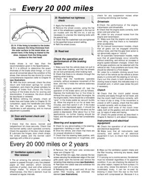 34
34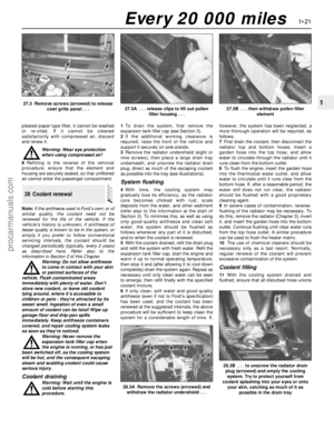 35
35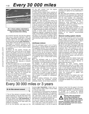 36
36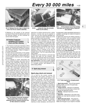 37
37 38
38 39
39 40
40 41
41 42
42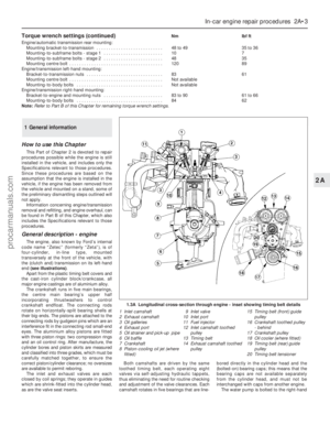 43
43 44
44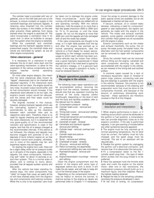 45
45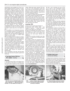 46
46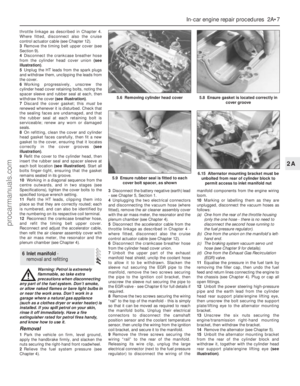 47
47 48
48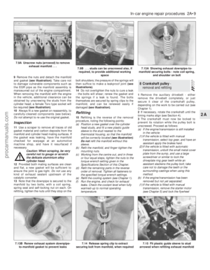 49
49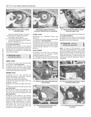 50
50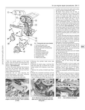 51
51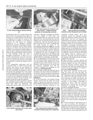 52
52 53
53 54
54 55
55 56
56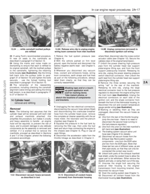 57
57 58
58 59
59 60
60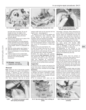 61
61 62
62 63
63 64
64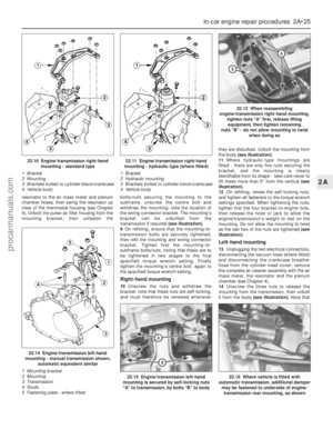 65
65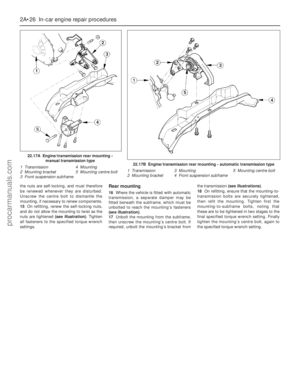 66
66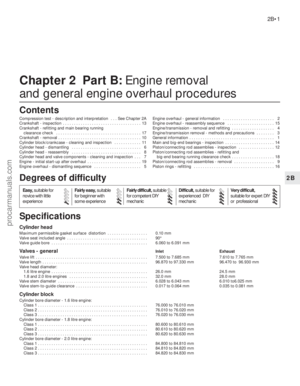 67
67 68
68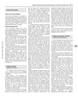 69
69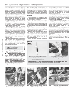 70
70 71
71 72
72 73
73 74
74 75
75 76
76 77
77 78
78 79
79 80
80 81
81 82
82 83
83 84
84 85
85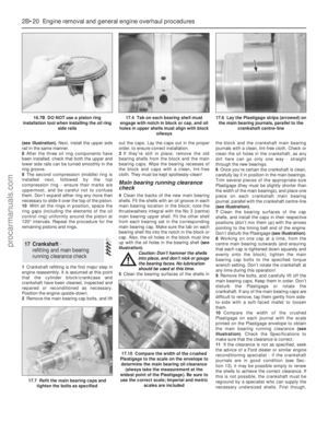 86
86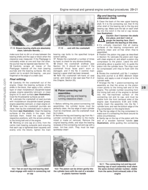 87
87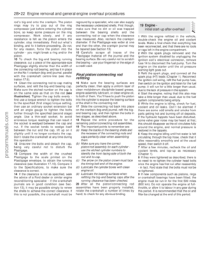 88
88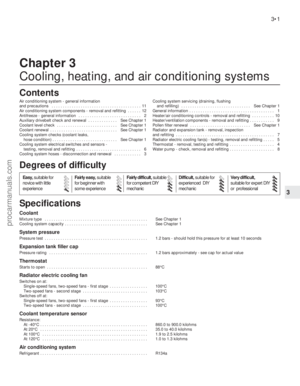 89
89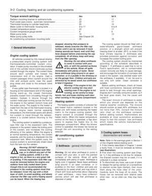 90
90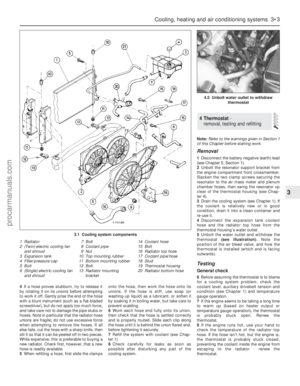 91
91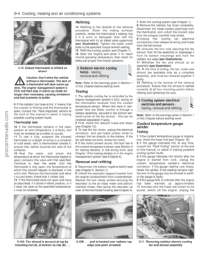 92
92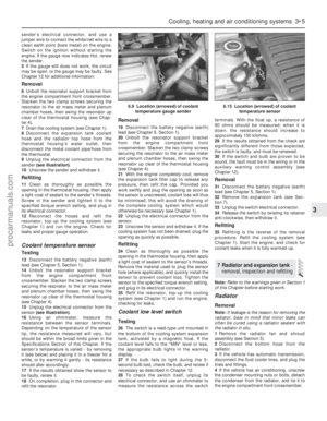 93
93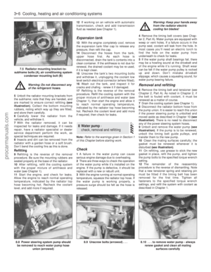 94
94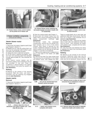 95
95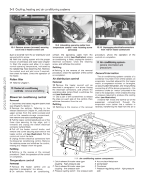 96
96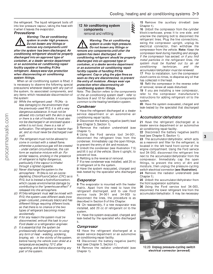 97
97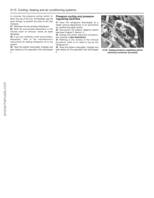 98
98 99
99 100
100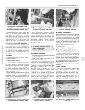 101
101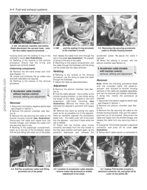 102
102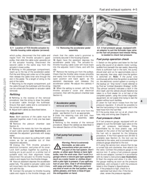 103
103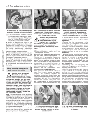 104
104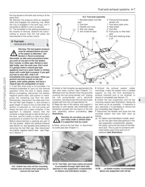 105
105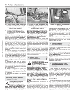 106
106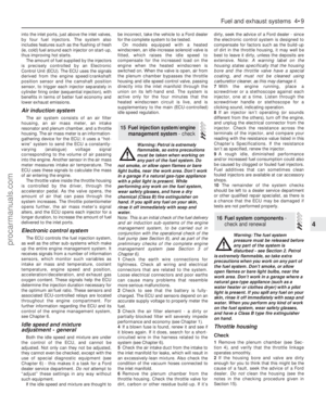 107
107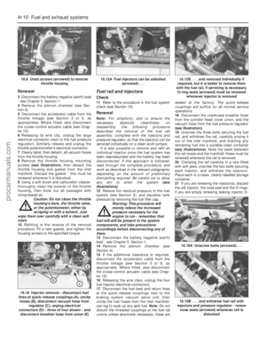 108
108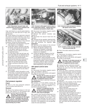 109
109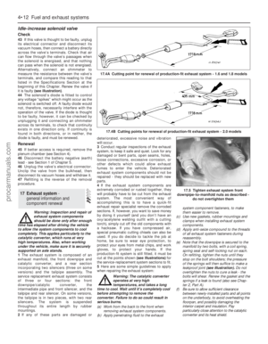 110
110 111
111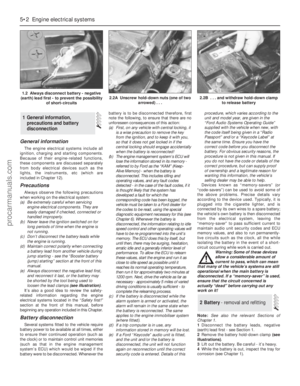 112
112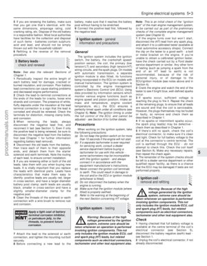 113
113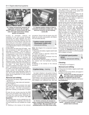 114
114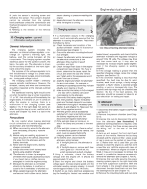 115
115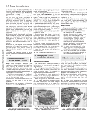 116
116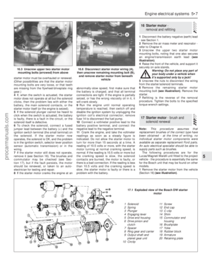 117
117 118
118 119
119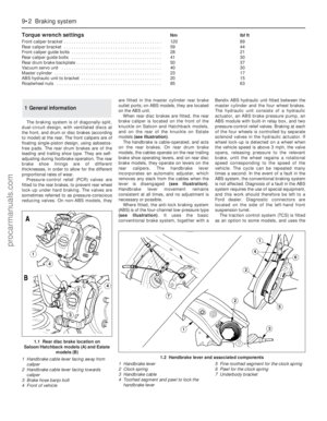 120
120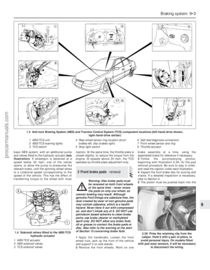 121
121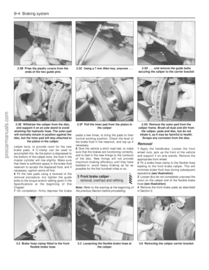 122
122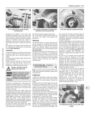 123
123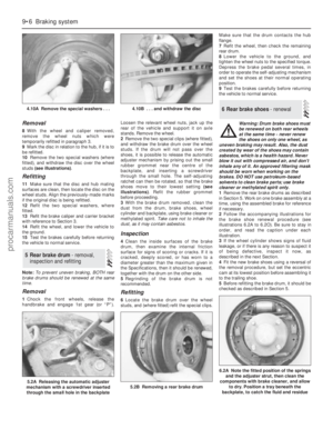 124
124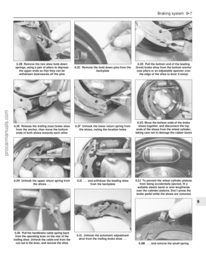 125
125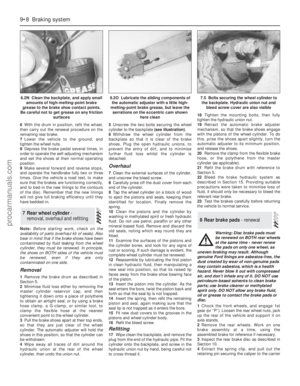 126
126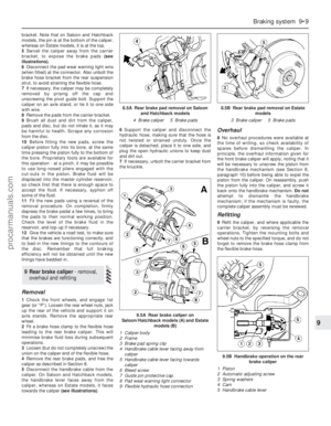 127
127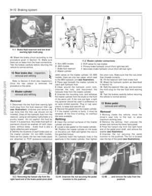 128
128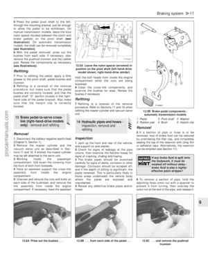 129
129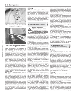 130
130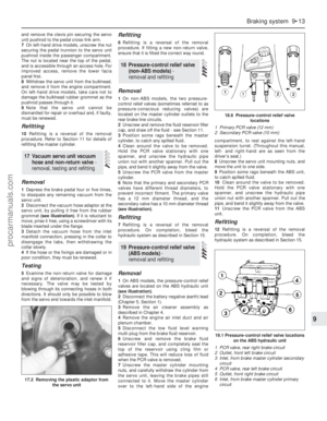 131
131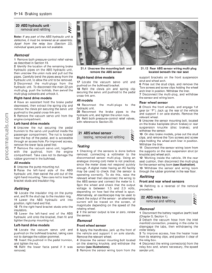 132
132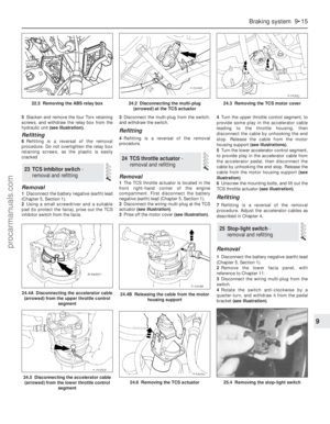 133
133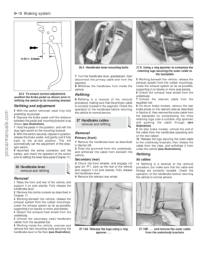 134
134 135
135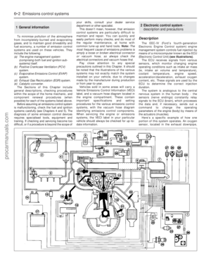 136
136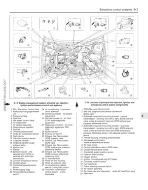 137
137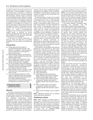 138
138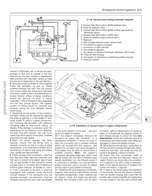 139
139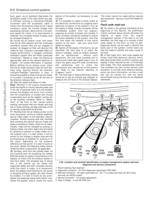 140
140 141
141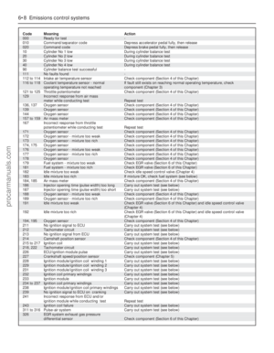 142
142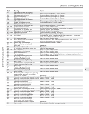 143
143 144
144 145
145 146
146 147
147 148
148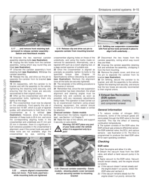 149
149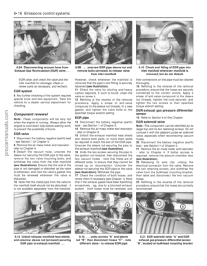 150
150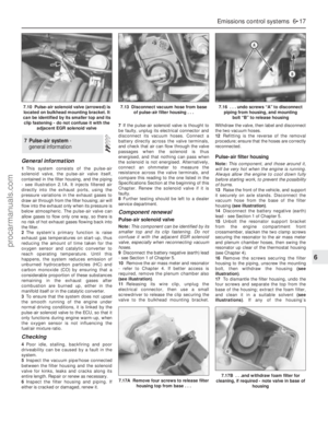 151
151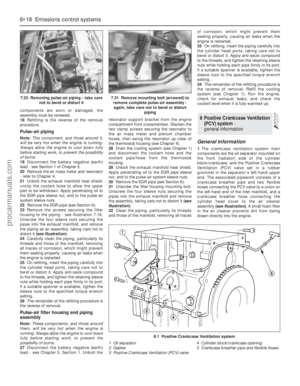 152
152 153
153 154
154 155
155 156
156 157
157 158
158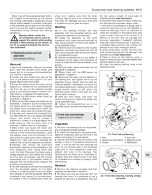 159
159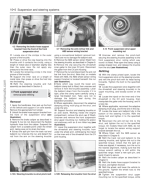 160
160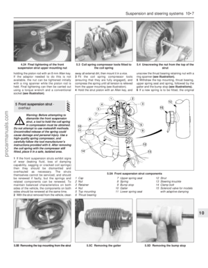 161
161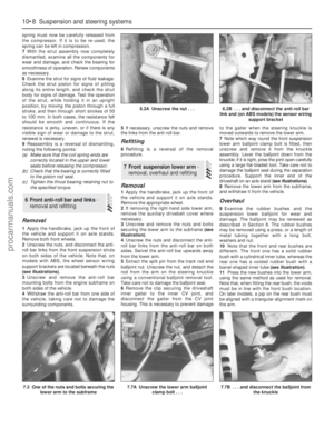 162
162 163
163 164
164 165
165 166
166 167
167 168
168 169
169 170
170 171
171 172
172 173
173 174
174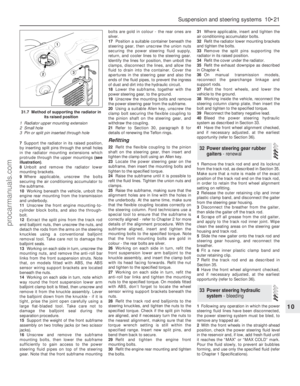 175
175 176
176 177
177 178
178 179
179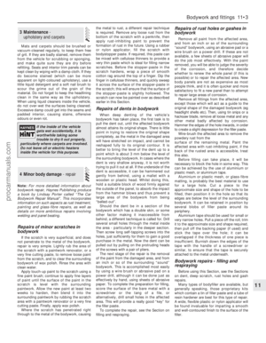 180
180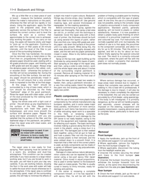 181
181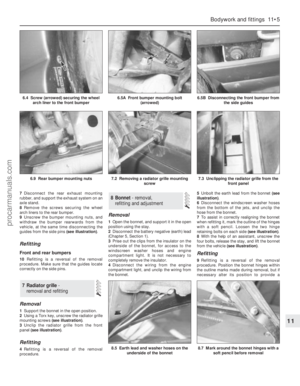 182
182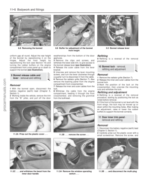 183
183 184
184 185
185 186
186 187
187 188
188 189
189 190
190 191
191 192
192 193
193 194
194 195
195 196
196 197
197 198
198 199
199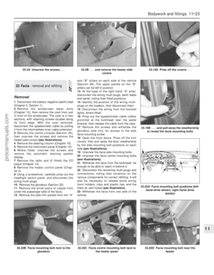 200
200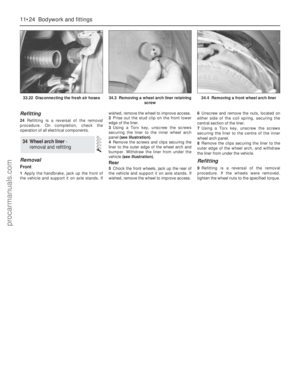 201
201 202
202 203
203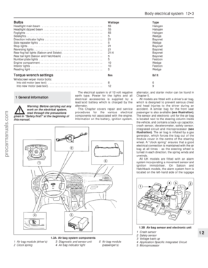 204
204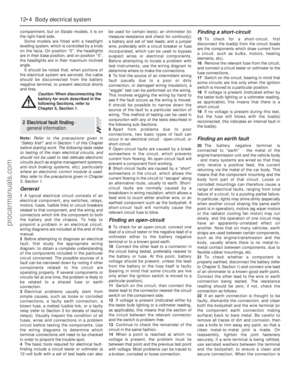 205
205 206
206 207
207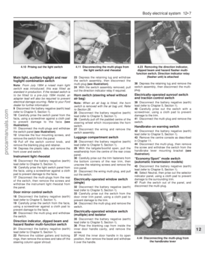 208
208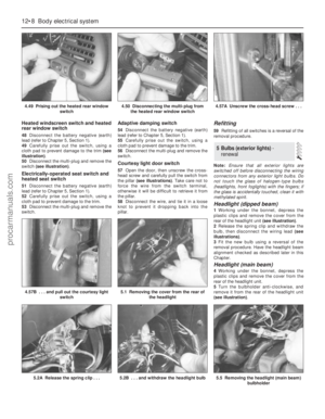 209
209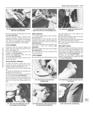 210
210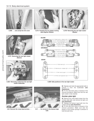 211
211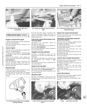 212
212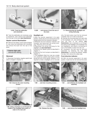 213
213 214
214 215
215 216
216 217
217 218
218 219
219 220
220 221
221 222
222 223
223 224
224 225
225 226
226 227
227 228
228 229
229 230
230 231
231 232
232 233
233 234
234 235
235 236
236 237
237 238
238 239
239 240
240 241
241 242
242 243
243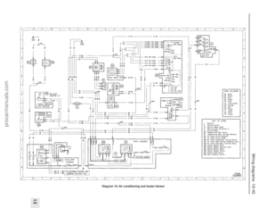 244
244 245
245 246
246 247
247 248
248 249
249 250
250 251
251 252
252 253
253 254
254 255
255 256
256 257
257 258
258 259
259 260
260 261
261 262
262 263
263 264
264 265
265 266
266 267
267 268
268 269
269 270
270 271
271 272
272 273
273 274
274 275
275 276
276 277
277 278
278