Page 169 of 279

2Position a trolley jack under the coil spring
area of the rear lower suspension arm, to
keep the coil spring in compression.
3Unscrew and remove the shock absorber
lower mounting bolt (see illustration).
4Unscrew and remove the upper mounting
bolt, and withdraw the shock absorber from
under the vehicle.
Testing
5Check the mounting rubbers for damage
and deterioration. If they are worn, they may
be renewed separately from the shock
absorber body.
6Mount the shock absorber in a vice,
gripping it by the lower mounting. Examine
the shock absorber for signs of fluid leakage.
Test the operation of the shock absorber by
moving it through a full stroke, and then
through short strokes of 50 to 100 mm. In
both cases, the resistance felt should be
smooth and continuous. If the resistance is
jerky or uneven, the shock absorber should be
renewed.
Refitting
7Refitting is a reversal of the removal
procedure, but tighten the mounting bolts to
the specified torque.
Removal
1Chock the front wheels, then jack up the
rear of the vehicle and support it on axle
stands. Remove both rear wheels.
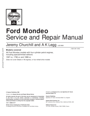
2Unscrew the nuts, and remove the washers
and bushes securing the anti-roll bar links to
the rear lower arms (see illustrations).
3Using a Torx key, unscrew the bolts
securing the anti-roll bar mounting clamps to
the rear suspension crossmember; release the
clamps, and withdraw the anti-roll bar from
under the vehicle (see illustration).
4Examine the rubber bushes for the
mounting clamps and links, and if necessary
renew them. The links are available
individually.
Refitting
5Locate the anti-roll bar on the rear
crossmember, then refit the clamps and
tighten the bolts to the specified torque.
6Refit the anti-roll bar links to the rear lower
arms, together with the bushes and washers.
Tighten the nuts to the specified torque, while
holding the actual links stationary in their
central position.
7Refit the rear wheels, and lower the vehicle
to the ground.
Note:Before attempting to remove the rear
suspension coil spring, a tool to hold the coil
spring in compression must be obtained.
Careful use of conventional coil spring
compressors will prove satisfactory.
Removal
1Chock the front wheels, then jack up the
rear of the vehicle and support it on axle
stands. Remove the appropriate wheel.
2Support the weight of the rear lower arm
beneath the coil spring position with a trolley
jack.
3Fit the coil spring compressor tool (ensuring
that it is fully engaged), and compress the coil
spring until all tension is relieved from the
upper mounting.
4Unscrew the nut, and remove the washerand bush attaching the anti-roll bar link to the
rear lower arm.
5Unscrew and remove the bolt securing the
rear lower arm to the knuckle (see
illustration).
6Unscrew and remove the bolt securing the
front lower arm to the knuckle (see
illustration).
7Lower the rear lower arm, and withdraw the
coil spring from under the vehicle. Take care
to keep the compressor tool in full
engagement with the coil spring (see
illustration).
8If a new coil spring is to be fitted, the
original coil spring must be released from the
compressor. If it is to be re-used, the coil
spring can be left in compression.
21 Rear coil spring (Estate
models) - removal and refitting20 Rear anti-roll bar and links
(Estate models) -
removal and refitting
Suspension and steering systems 10•15
10
20.3 Anti-roll bar mounting clamp on the
rear suspension crossmember21.5 Rear lower arm-to-knuckle mounting
bolt21.6 Front lower arm-to-knuckle mounting
bolt
19.3 Rear shock absorber lower mounting
bolt (Estate)20.2A Mounting nut (arrowed) and rubber
bush securing the rear anti-roll bar link to
the rear lower arm
20.2B View of the anti-roll bar link nut
through the rear lower arm
procarmanuals.com
Page 170 of 279
. Delay fully tightening
the two low")
Refitting
9Refitting is a reversal of the removal
procedure, but make sure that the coil spring
is located correctly in the upper and lower
seats (see illustration). Delay fully tightening
the two lower arm mounting bolts until the
weight of the vehicle is on the rear
suspension. Finally check, and if necessary
adjust, the rear wheel toe setting as described
in Section 36.
Removal
1Remove the rear suspension coil spring as
described in Section 21.
2The bolt securing the rear lower arm to the
crossmember has an eccentric head and
spacer, which are used to adjust the rear toe
setting. Before removing this bolt, mark its
position, using a scriber or similar sharp
instrument through the aperture in the
crossmember.
3Unscrew and remove the bolt securing the
rear lower arm to the crossmember. The bolt
may be removed through the aperture in the
crossmember. Recover the eccentric spacer
(see illustration).
4Withdraw the rear lower arm from under the
vehicle.
Refitting
5Refitting is a reversal of the removal
procedure, but delay fully tightening the lower
arm mounting bolts until the weight of the
vehicle is on the rear suspension. Finally
check, and if necessary adjust, the rear wheel
toe setting as described in Section 36.
Removal
1Chock the front wheels, then jack up the
rear of the vehicle and support it on axle
stands. Remove the appropriate wheel.
2Unscrew and remove the bolt securing the
front lower arm to the crossmember (see
illustration).
3Unscrew and remove the bolt securing the
front lower arm to the knuckle, and withdraw
the arm from under the vehicle (see
illustration).
Refitting
4Refitting is a reversal of the removal
procedure, but delay fully tightening the
mounting bolts until the weight of the vehicle
is on the rear suspension.
Removal
1Chock the front wheels, then jack up the
rear of the vehicle and support it on axle
stands. Remove the appropriate wheel.
2Using a trolley jack, support the rear lower
arm beneath the coil spring position.
3Unscrew and remove the bolt securing the
upper arm to the knuckle (see illustration).
4Unscrew and remove the bolt securing the
upper arm to the crossmember, and withdraw
the arm from under the vehicle.
Refitting
5Refitting is a reversal of the removal
procedure, but delay fully tightening the
mounting bolts until the weight of the vehicle
is on the rear suspension.
Removal
1Chock the front wheels, then jack up the
rear of the vehicle and support it on axle
stands. Remove the appropriate wheel.
25 Rear suspension tie-bar
(Estate models) -
removal and refitting
24 Rear suspension upper arm
(Estate models) -
removal and refitting
23 Rear suspension front lower
arm (Estate models)-
removal and refitting
22 Rear suspension rear lower
arm (Estate models) -
removal and refitting
10•16 Suspension and steering systems
21.7 Removing the coil spring, with
compressor tool attached, from under the
vehicle21.9 Correct location of the coil spring in
the upper seat (arrowed)22.3 Bolts securing the rear lower arms to
the crossmember - note the eccentric
spacers
23.2 Front lower arm-to-crossmember
securing bolt23.3 Front lower arm (arrowed)24.3 Bolt (arrowed) securing the upper
arm to the knuckle
procarmanuals.com
Page 171 of 279

2Using a trolley jack, support the rear lower
arm beneath the coil spring position.
3Unscrew and remove the bolt securing the
rear shock absorber to the knuckle.
4Where applicable, release the ABS wheel
sensor lead from the tie-bar.
5Detach the handbrake cable from the tie-
bar bracket.
6Refer to Chapter 9, and disconnect the
handbrake cable from the rear brake shoes or
rear caliper, as applicable. Pass the cable
through the hole in the tie-bar.
7Unscrew and remove the three bolts
securing the tie-bar to the knuckle (see
illustration).
8Unbolt the tie-bar bracket from the
underbody, and withdraw the assembly from
under the vehicle (see illustrations).
9Mount the tie-bar in a vice, then unscrew
the bolt, and separate the tie-bar from its
bracket.
10It is not possible to renew the rubber bush
in the tie-bar, and if it is excessively worn, the
complete tie-bar must be renewed.
Refitting
11Refitting is a reversal of the removal
procedure, but delay fully tightening the bolt
which secures the arm to the bracket until the
weight of the vehicle is on the rear
suspension. On completion, check the
operation of the handbrake.
Removal
1Chock the front wheels, then jack up the
rear of the vehicle and support on axles
stands. Remove both rear wheels. Make sure
that the vehicle is supported high enough for
the crossmember to be removed.
2Disconnect the handbrake rear cables from
the front primary cable, as described in
Chapter 9.
3Where applicable, remove the ABS wheel
sensors from the rear knuckles, and
disconnect the wiring leads from the clips as
described in Chapter 9.
4Disconnect the flexible brake hoses from
the brackets on both sides of the
crossmember, as described in Chapter 9.
5Working on each side of the vehicle, unbolt
the tie-bar brackets from the underbody.
6Support the rear suspension crossmember
on a trolley jack.
7Unscrew the mounting bolts, and lower the
crossmember to the ground (see
illustrations).
8If necessary, remove the suspension
components from the crossmember as
described in the appropriate Sections of this
Chapter.
Refitting
9Refitting is a reversal of the removal
procedure, noting the following points:
(a) When raising the crossmember, note that
guide pins are provided to ensure correct
alignment (see illustration).
(b) Delay fully tightening the suspension
mounting bolts until the weight of the
vehicle is on the rear suspension.
(c) Tighten all bolts to the specified torque.
(d) Bleed the brake hydraulic system as
described in Chapter 9.
(e) Check, and if necessary adjust, the rear
wheel toe setting as described in Section 36.
Warning: All models are equipped
with an air bag system. Make
sure that the safety
recommendations given in Chapter 12 are
followed, to prevent personal injury.
Removal
1Disconnect the battery negative (earth) lead
(refer to Chapter 5, Section 1).
Warning: Before proceeding, wait
a minimum of 15 minutes, as a
precaution against accidental
firing of the air bag unit. This
period ensures that any stored energy in
the back-up capacitor is dissipated.
27 Steering wheel -
removal and refitting
26 Rear suspension
crossmember (Estate
models) - removal and refitting
Suspension and steering systems 10•17
10
26.7A Rear suspension crossmember rear
mounting bolt26.7B Rear suspension crossmember
front mounting bolt26.9 Guide pin (arrowed) for correct
alignment of the rear crossmember
25.7 Bolts (arrowed) securing the rear
suspension tie-bar to the knuckle25.8A Tie-bar bracket front bolt (arrowed)
on the underbody25.8B Tie-bar bracket rear bolt (arrowed)
on the underbody
procarmanuals.com
Page 172 of 279

2Turn the steering wheel so that the front
wheels are in the straight-ahead position.
3Unscrew the screws, and remove the
steering column upper and lower shrouds.
4From the rear of the steering wheel,
unscrew the air bag module mounting screws.
5Carefully lift the module from the steering
wheel, and disconnect the air bag multi-plug
and horn wiring connections.
Warning: Position the air bag
module in a safe place, with the
mechanism facing downwards as
a precaution against accidental
operation.
6Make sure that the steering lock is not
engaged. Unscrew the retaining bolt from the
centre of the steering wheel (see illustration).
7Remove the steering wheel from the top ofthe column, while feeding the horn and air bag
wiring through the hole in the steering wheel
hub (see illustration).
Refitting
8Make sure that the front wheels are still
facing straight-ahead, then locate the steering
wheel on the top of the steering column.
9Refit the retaining bolt, and tighten it to the
specified torque while holding the steering
wheel (see illustration). Do not tighten the
bolt with the steering lock engaged, as this
may damage the lock.
10Reconnect the horn wiring connections
and air bag multi-plug.
11Locate the air bag module/horn contact
on the steering wheel, then insert the
mounting screws and tighten them.12Refit the steering column upper and lower
shrouds. Insert and tighten the screws.
13Reconnect the battery negative lead.
Warning: All models are equipped
with an air bag system. Make
sure that the safety
recommendations given in
Chapter 12 are followed, to prevent
personal injury.
Removal
1Disconnect the battery negative (earth) lead
(refer to Chapter 5, Section 1).
Warning: Before proceeding, wait
a minimum of 15 minutes, as a
precaution against accidental
firing of the air bag unit. This
period ensures that any stored energy in
the back-up capacitor is dissipated.
2Turn the steering wheel so that the front
wheels are in the straight-ahead position.
3Remove the ignition key, then turn the
steering wheel slightly as necessary until the
steering lock engages.
4Unscrew the screws, and remove the
steering column lower and upper shrouds. As
the lower shroud is being removed, it will be
necessary to remove the rubber ring from the
ignition switch/steering lock (see
illustrations).
28 Steering column - removal,
inspection and refitting
10•18 Suspension and steering systems
27.6 Removing the steering wheel
retaining bolt27.7 Feeding the horn and air bag wiring
through the hole in the steering wheel hub27.9 Tightening the steering wheel
retaining bolt
28.4C . . . and remove the lower shroud28.4D Upper shroud retaining screws
(arrowed)
28.4A Unscrew the screws from the lower
shroud . . .28.4B . . . remove the rubber ring . . .
28.4E Removing the upper shroud
procarmanuals.com
Page 173 of 279
.
6Unscrew the clamp plate bolt securing the
steering column shaft to the flexible coupling.
Swivel the clamp plate around, and disengage")
5Remove the driver’s side lower facia panel
(see Chapter 11).
6Unscrew the clamp plate bolt securing the
steering column shaft to the flexible coupling.
Swivel the clamp plate around, and disengage
it from the flexible coupling stub (see
illustrations).
7Release the cable tie from the wiring loom
at the steering column, and disconnect the
multi-plugs (see illustrations).
8Unscrew and remove the steering column
mounting bolts, then slide the column
upwards to disengage the retaining tab from
the groove in the cross-beam bracket, and
withdraw it from inside the vehicle (see
illustrations).
Inspection
9With the steering column removed, check
the universal joints for wear, and examine thecolumn upper and lower shafts for any signs
of damage or distortion (see illustration).
Where evident, the column should be
renewed complete.
10Examine the height adjustment lever
mechanism for wear and damage (see
illustration).
11With the steering lock disengaged, turn
the inner column, and check the upper and
lower bearings for smooth operation. The
bearings are obtainable separately, and
should be renewed if necessary. Dismantling
and reassembly of the column assembly is a
relatively easy operation.
Refitting
12Locate the steering column on its bracket,
making sure that the tab slides down into the
groove correctly.13Insert the mounting bolts and tighten to
the specified torque (see illustration).
14Reconnect the multi-plugs, and secure
the wiring loom with the cable tie.
Suspension and steering systems 10•19
10
28.9 Steering column and universal joint28.10 Height adjustment lever mechanism28.13 Tightening the steering column
mounting bolts
28.7C . . . and main multi-plug from the
steering column28.8A Steering column mounting bolt
locations (arrowed)28.8B Removing the steering column
28.6A Unscrew the clamp plate bolt . . .28.6B . . . and swivel the clamp plate
around28.7A Disconnecting the multi-plug from
the ignition switch
28.7B Disconnecting the small
multi-plug . . .
procarmanuals.com
Page 174 of 279

15Locate the steering column shaft on the
flexible coupling, swivel the clamp plate
round, then insert the bolt and tighten to the
specified torque.
16Refit the driver’s side lower trim panel.
17Refit the steering column upper and lower
shrouds.
18Reconnect the battery negative lead.
Removal
1Disconnect the battery negative (earth) lead
(refer to Chapter 5, Section 1).
2Turn the steering wheel so that the front
wheels are in the straight-ahead position.
Remove the ignition key, then turn the
steering wheel slightly as necessary until the
steering lock engages.
3Unscrew the clamp plate bolt securing the
steering column shaft to the flexible coupling.
Swivel the clamp plate around, and disengage
it from the flexible coupling stub.
4Carefully prise the rubber boot from the
bulkhead, and withdraw it into the passenger
compartment. Take care not to damage the
sealing lip of the boot.
5Using an Allen key, unscrew the clamp bolt
securing the flexible coupling to the pinion
shaft on the steering gear, and withdraw the
coupling from inside the vehicle.
Refitting
6Refitting is a reversal of the removal
procedure, but tighten the clamp bolts to the
specified torque. Make sure that the rubber
boot engages correctly in the bulkhead and
on the flexible coupling.
Removal
1Remove the steering column flexible
coupling as described in Section 29.
2Apply the handbrake, then jack up the frontof the vehicle and support it on axle stands.
Remove both front wheels.
3Working beneath the vehicle, unbolt the
rear engine mounting from the transmission
and underbody.
4Extract the split pins from the track rod end
balljoint nuts, then unscrew the nuts, and
detach the rods from the arms on the steering
knuckles using a conventional balljoint
removal tool. Take care not to damage the
balljoint seals.
5Position a suitable container beneath the
steering gear, then unscrew the union nuts
securing the power steering fluid supply,
return, and cooler lines to the steering gear.
Identify the lines for position, then unbolt the
clamps, disconnect the lines, and allow the
fluid to drain into the container. Cover the
apertures in the steering gear and also the
ends of the fluid pipes, to prevent the ingress
of dust and dirt into the hydraulic circuit.
6Unscrew and remove the steering gear
mounting bolts. The bolts are located on top
of the steering gear, and are difficult to reach.
Ideally, the special U-shaped Ford spanner
should be used, but it is just possible to reach
them with a normal spanner (see illustration).
7Withdraw the steering gear through the
wheel arch.
Refitting
8If the steering gear is being replaced with a
new one, the new unit will be supplied
together with union nuts already fitted. The
new nuts must only be used with new feed
and return lines - otherwise, they must be
removed and discarded. If the original lines
and union nuts are being used, the Teflon
rings on the union nuts must be renewed. To
do this, the rings must be expanded
individually onto a fitting adaptor (see
illustration), then located in the grooves of
the union nuts.
9Locate the steering gear on the subframe,
and insert the two mounting bolts. Tighten the
bolts to the specified torque (see illustration).
Note that, if the special Ford tool is being
used, the bottom of the tool must be turned
anti-clockwise in order to tighten the
mounting bolts.10Remove the covers from the apertures on
the steering gear, then reconnect the fluid
lines and tighten the union nuts to the
specified torque. Refit the clamps and tighten
the bolts.
11Refit the track rod end balljoints to the
steering knuckles, and tighten the nuts to the
specified torque. Check that the split pin
holes are aligned; if necessary, turn the nuts
to the nearest alignment, making sure that the
torque wrench setting is still within the
specified range. Insert new split pins, and
bend them back to secure.
12Refit the rear engine mounting to the
transmission and underbody, and tighten the
bolts to the specified torque.
13Refit the front wheels, and lower the
vehicle to the ground.
14Refit the steering column flexible coupling
with reference to Section 29.
15Bleed the power steering hydraulic
system as described in Section 33.
16Have the front wheel alignment checked,
and if necessary adjusted, at the earliest
opportunity (refer to Section 36).Removal
1Disconnect the battery negative (earth) lead
(refer to Chapter 5, Section 1).
2Working inside the vehicle, unscrew the
clamp plate bolt securing the steering column
shaft to the flexible coupling. Swivel the clamp
plate around, and disengage it from the
flexible coupling stub.
3Apply the handbrake, then jack up the front
of the vehicle and support it on axle stands.
Remove both wheels.
4On manual transmission models,
disconnect the gearchange linkage and
support rods from the transmission, as
described in Chapter 7, Part A.
5Remove the exhaust downpipe complete,
as described in Chapter 4.
6Remove the cover from under the radiator
by unscrewing the screws and releasing the
clips.
31 Power steering gear
(left-hand-drive models with
ABS) - removal and refitting
30 Power steering gear (all except
left-hand-drive models with
ABS) - removal and refitting
29 Steering column flexible
coupling - removal and refitting
10•20 Suspension and steering systems
30.6 U-shaped Ford spanner for
unscrewing the steering gear mounting
bolts
30.8 Using an adaptor to fit the Teflon
rings to the union nuts
1 Adaptor 2 Teflon ring 3 Union nut
4 Groove location for the Teflon ring
30.9 Tightening the steering gear
mounting bolts using the U-shaped
spanner (arrowed)
procarmanuals.com
Page 175 of 279
.
8Unbolt")
7Support the radiator in its raised position,
by inserting split pins through the small holes
in the radiator mounting extensions which
protrude through the upper mountings (see
illustration).
8Unbolt and remove the radiator lower
mounting brackets.
9Where applicable, unscrew the bolts
securing the air conditioning accumulator to
the subframe.
10Working beneath the vehicle, unbolt the
engine rear mounting from the transmission
and underbody.
11Unscrew the front engine mounting-to-
cylinder block bolts, and also the through-
bolt.
12Extract the split pins from the track rod
end balljoint nuts, then unscrew the nuts, and
detach the rods from the arms on the steering
knuckles using a conventional balljoint
removal tool. Take care not to damage the
balljoint seals.
13Working on each side in turn, unscrew the
mounting nuts, and remove the anti-roll bar
links from the front suspension struts. Note
that, on models fitted with ABS, the ABS
sensor wiring support brackets are located
beneath the nuts.
14Working on each side in turn, note which
way round the front suspension lower arm
balljoint clamp bolt is fitted, then unscrew and
remove it from the knuckle assembly. Lever
the balljoint down from the knuckle - if it is
tight, prise the joint open carefully using a
large flat-bladed tool. Take care not to
damage the balljoint seal during the
separation procedure.
15Support the weight of the front subframe
assembly on two trolley jacks (or two scissor
jacks).
16Unscrew and remove the subframe
mounting bolts, then lower the subframe
sufficiently to gain access to the power
steering fluid pipes on top of the steering
gear. Note that the front subframe mountingbolts are gold in colour - the rear ones are
silver.
17Position a suitable container beneath the
steering gear, then unscrew the union nuts
securing the power steering fluid supply,
return, and cooler lines to the steering gear.
Identify the lines for position, then unbolt the
clamps, disconnect the lines, and allow the
fluid to drain into the container. Cover the
apertures in the steering gear and also the
ends of the fluid pipes, to prevent the ingress
of dust and dirt into the hydraulic circuit.
18Lower the subframe, together with the
power steering gear, to the ground.
19Unscrew the mounting bolts and remove
the power steering gear from the subframe.
20Using a suitable Allen key, unscrew the
clamp bolt securing the flexible coupling to
the pinion shaft on the steering gear, and
withdraw the coupling.
21Refer to Section 30, paragraph 8 for
details of renewing the Teflon rings.Refitting
22Refit the flexible coupling to the pinion
shaft on the steering gear, then insert and
tighten the clamp bolt using an Allen key.
23Locate the power steering gear on the
subframe, then insert the mounting bolts and
tighten to the specified torque.
24Raise the subframe until it is possible to
refit the fluid lines. Tighten the union nuts and
clamps.
25Raise the subframe, making sure that the
alignment holes are in line with the holes in
the underbody. At the same time, make sure
that the flexible coupling locates correctly on
the steering column. Ford technicians use a
special tool to ensure that the subframe is
correctly aligned - refer to Chapter 2 for more
details of the alignment procedure. With the
subframe aligned, insert and tighten the
mounting bolts to the specified torque. Note
that the front mounting bolts are gold in
colour - the rear bolts are silver.
26Working on each side in turn, refit the
front suspension lower arm balljoint to the
knuckle assembly, and insert the clamp bolt
with its head facing forwards. Refit the nut
and tighten to the specified torque.
27Working on each side in turn, refit the
anti-roll bar links and tighten the mounting
nuts to the specified torque. On models fitted
with ABS, don’t forget to locate the wheel
sensor wiring support brackets beneath the
nuts.
28Refit the track rod end balljoints to the
steering knuckles, and tighten the nuts to the
specified torque. Check if the split pin holes
are aligned, and if necessary turn the nuts to
the nearest alignment, making sure that the
torque wrench setting is still within the
specified range. Insert new split pins, and
bend them back to secure.
29Refit and tighten the engine front
mounting bolts.
30Refit the engine rear mounting and tighten
the bolts.31Where applicable, insert and tighten the
air conditioning accumulator bolts.
32Refit the radiator lower mounting brackets
and tighten the bolts.
33Remove the split pins supporting the
radiator in its raised position.
34Refit the cover under the radiator.
35Refit the exhaust downpipe as described
in Chapter 4.
36On manual transmission models,
reconnect the gearchange linkage and
support rods.
37Refit the front wheels, and lower the
vehicle to the ground.
38Working inside the vehicle, reconnect the
steering column clamp plate, then insert the
bolt and tighten to the specified torque.
39Reconnect the battery negative lead.
40Bleed the power steering hydraulic
system as described in Section 33.
41Have the front wheel alignment checked,
and if necessary adjusted, at the earliest
opportunity (refer to Section 36).
1Remove the track rod end and its locknut
from the track rod, as described in Section 35.
Make sure that a note is made of the exact
position of the track rod end on the track rod,
in order to retain the front wheel alignment
setting on refitting.
2Release the outer retaining clip and inner
plastic clamp band, and disconnect the gaiter
from the steering gear housing.
3Disconnect the breather from the gaiter,
then slide the gaiter off the track rod.
4Scrape off all grease from the old gaiter,
and apply to the track rod inner joint. Wipe
clean the seating areas on the steering gear
housing and track rod.
5Slide the new gaiter onto the track rod and
steering gear housing, and reconnect the
breather.
6Fit a new inner plastic clamp band and
outer retaining clip.
7Refit the track rod end as described in
Section 35.
8Have the front wheel alignment checked,
and if necessary adjusted, at the earliest
opportunity (refer to Section 36).
1Following any operation in which the power
steering fluid lines have been disconnected,
the power steering system must be bled, to
remove any trapped air.
2With the front wheels in the straight-ahead
position, check the power steering fluid level
in the reservoir and, if low, add fresh fluid until
it reaches the “MAX” or “MAX COLD” mark.
Pour the fluid slowly, to prevent air bubbles
forming, and use only the specified fluid (refer
to Chapter 1 Specifications).
33 Power steering hydraulic
system - bleeding
32 Power steering gear rubber
gaiters - renewal
Suspension and steering systems 10•21
10
31.7 Method of supporting the radiator in
its raised position
1 Radiator upper mounting extension
2 Small hole
3 Pin or split pin inserted through hole
procarmanuals.com
Page 176 of 279

3Start the engine, and allow it to run at a fast
idle. Check the hoses and connections for
leaks.
4Stop the engine, and recheck the fluid level.
Add more if necessary, up to the “MAX” or
“MAX COLD” mark.
5Start the engine again, allow it to idle, then
bleed the system by slowly turning the
steering wheel from side to side several times.
This should purge the system of all internal
air. However, if air remains in the system
(indicated by the steering operation being very
noisy), leave the vehicle overnight, and repeat
the procedure again the next day.
6If air still remains in the system, it may be
necessary to resort to the Ford method of
bleeding, which uses a vacuum pump. Turn
the steering to the right until it is near the stop,
then fit the vacuum pump to the fluid
reservoir, and apply 0.15 bars of vacuum.
Maintain the vacuum for a minimum of
5 minutes, then repeat the procedure with the
steering turned to the left.
7Keep the fluid level topped-up throughout
the bleeding procedure; note that, as the fluid
temperature increases, the level will rise.
8On completion, switch off the engine, and
return the front wheels to the straight-ahead
position.
Removal
1Disconnect the battery negative (earth) lead
(refer to Chapter 5, Section 1).
2Unscrew and remove the bolt securing the
hydraulic fluid line support to the engine lifting
bracket on the right-hand side of the engine.
3Unscrew and remove the bolt securing the
hydraulic fluid line support to the pump
mounting bracket.
4Position a suitable container beneath the
power steering pump, to catch spilt fluid.
5Loosen the clip, and disconnect the fluid
supply hose from the pump inlet. Plug the
hose, to prevent the ingress of dust and dirt.
6Unscrew the union nut, and disconnect the
high-pressure line from the pump. Allow the
fluid to drain into the container.
7Apply the handbrake, then jack up the front
of the vehicle and support it on axle stands.
Remove the right-hand front wheel.
8Unbolt and remove the lower drivebelt
cover.
9Using a spanner, rotate the drivebelt
tensioner in a clockwise direction to release
the belt tension, then slip the drivebelt off the
pulleys and remove from the vehicle. Refer to
Chapter 1 if necessary.
10Unscrew and remove the four mounting
bolts, and withdraw the power steering pump
from its bracket. Access to the bolts on the
right-hand side of the engine is gained by
turning the pump pulley until a hole lines up
with the bolt.
Refitting
11Locate the power steering pump on the
mounting bracket, and secure with the four
bolts. Tighten the bolts to the specified
torque.
12Slip the drivebelt over the pulleys, then
rotate the drivebelt tensioner in a clockwise
direction, and locate the drivebelt on it.
Release the tensioner to tension the drivebelt.
13Refit the lower belt cover.
14Refit the right-hand front wheel, and lower
the vehicle to the ground.
15If necessary, the sealing ring on the high-
pressure outlet should be renewed, using the
same procedure as described in Section 30,
paragraph 8.
16Reconnect the high-pressure line to the
pump, and tighten the union nut.
17Reconnect the fluid supply hose to the
pump inlet, and tighten the clip.
18Refit the hydraulic fluid line support to the
pump mounting bracket, and tighten the bolt.
19Refit the hydraulic fluid line support to the
engine lifting bracket on the right-hand side of
the engine, and tighten the bolt.
20Reconnect the battery negative lead.
21Bleed the power steering hydraulic
system as described in Section 33.
1Apply the handbrake, then jack up the front
of the vehicle and support it on axle stands.
Remove the appropriate front roadwheel.
2Using a suitable spanner, slacken the
locknut on the track rod by a quarter-turn.
Hold the track rod end stationary with another
spanner engaged with the special flats while
loosening the locknut.
3Extract the split pin, then unscrew and
remove the track rod end balljoint retaining
nut.
4To release the tapered shank of the balljoint
from the steering knuckle arm, use a balljoint
separator tool (if the balljoint is to be re-used,
take care not to damage the dust cover when
using the separator tool) (see illustration).
5Count the number of exposed threads
visible on the inner section of the track rod,
and record this figure.
6Unscrew the track rod end from the track
rod, counting the number of turns necessary
to remove it. If necessary, hold the track rod
stationary with grips.
Refitting
7Screw the track rod end onto the track rod
by the number of turns noted during removal,
until it just contacts the locknut.
8Engage the shank of the balljoint with the
steering knuckle arm, and refit the nut.
Tighten the nut to the specified torque. If the
balljoint shank turns while the nut is being
tightened, press down on the balljoint. The
tapered fit of the shank will lock it, and
prevent rotation as the nut is tightened.9Check that the split pin holes in the nut and
balljoint shank are aligned. If necessary turn
the nut to the nearest alignment, making sure
that the torque wrench setting is still within
the specified range. Insert a new split pin, and
bend it back to secure.
10Now tighten the locknut, while holding the
track rod end as before.
11Refit the roadwheel, and lower the vehicle
to the ground.
12Finally check, and if necessary adjust, the
front wheel alignment as described in Sec-
tion 29.
1Accurate front wheel alignment is essential
to provide positive steering, and to prevent
excessive tyre wear. Before considering the
steering/suspension geometry, check that the
tyres are correctly inflated, that the front
wheels are not buckled, and that the steering
linkage and suspension joints are in good
order, without slackness or wear.
2Wheel alignment consists of four factors
(see illustration):
Camberis the angle at which the front
wheels are set from the vertical, when viewed
from the front of the vehicle. “Positive
camber” is the amount (in degrees) that the
wheels are tilted outward at the top of the
vertical. Castoris the angle between the
steering axis and a vertical line, when viewed
from each side of the car. “Positive castor” is
when the steering axis is inclined rearward at
the top.
Steering axis inclinationis the angle (when
viewed from the front of the vehicle) between
the vertical and an imaginary line drawn
through the suspension strut upper mounting
and the lower suspension arm balljoint.
Toe settingis the amount by which the
distance between the front inside edges of the
roadwheels (measured at hub height) differs
from the diametrically-opposite distance
measured between the rear inside edges of
the front roadwheels.
3With the exception of the toe setting, all
other steering angles are set during
manufacture, and no adjustment is possible. It
36 Wheel alignment and steering
angles - general information35 Track rod end - renewal34 Power steering pump -
removal and refitting
10•22 Suspension and steering systems
35.4 Using a balljoint separator tool to
release the track rod end balljoint
procarmanuals.com
 1
1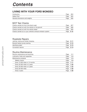 2
2 3
3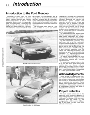 4
4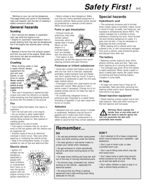 5
5 6
6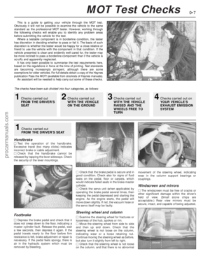 7
7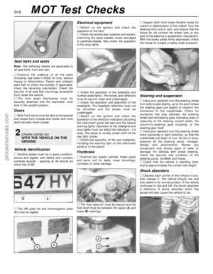 8
8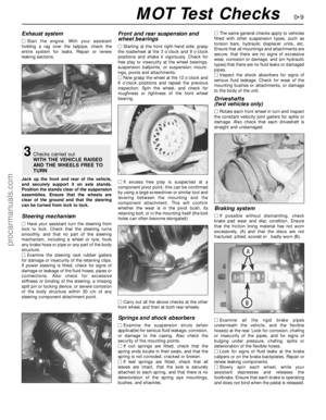 9
9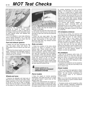 10
10 11
11 12
12 13
13 14
14 15
15 16
16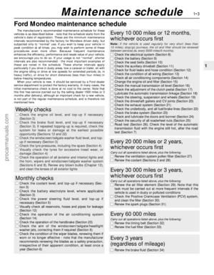 17
17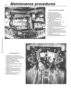 18
18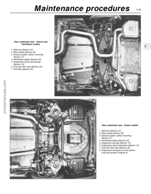 19
19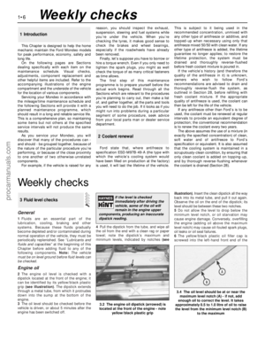 20
20 21
21 22
22 23
23 24
24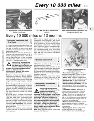 25
25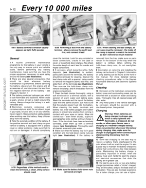 26
26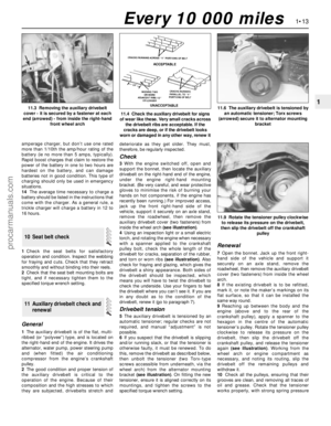 27
27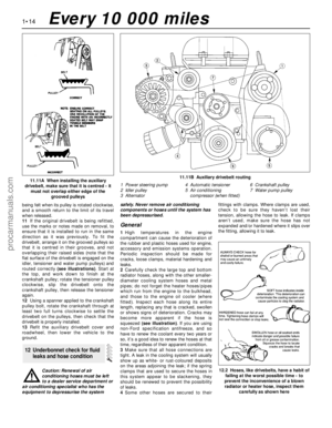 28
28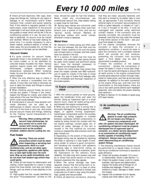 29
29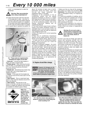 30
30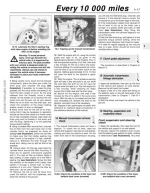 31
31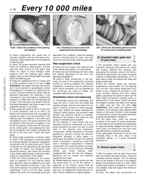 32
32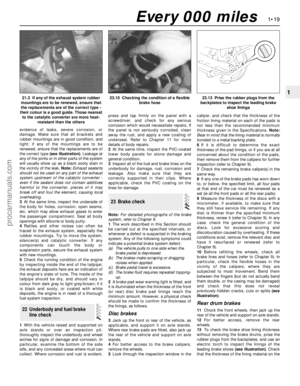 33
33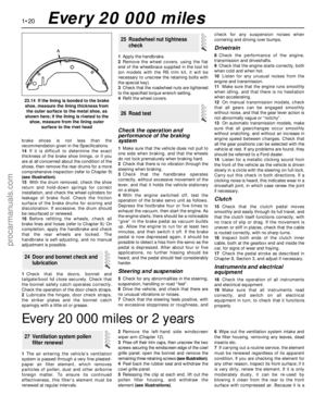 34
34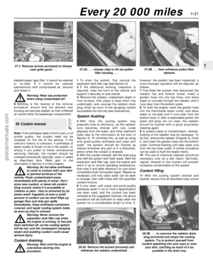 35
35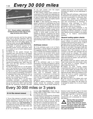 36
36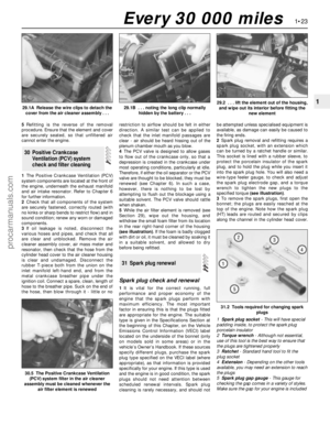 37
37 38
38 39
39 40
40 41
41 42
42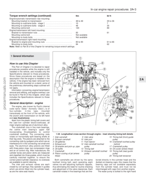 43
43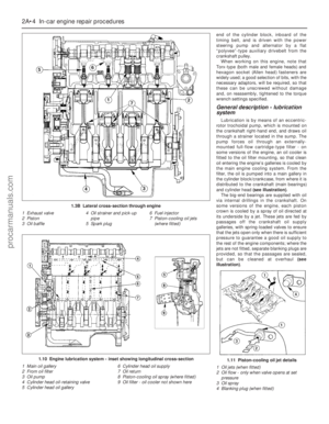 44
44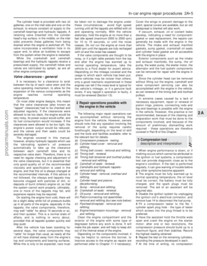 45
45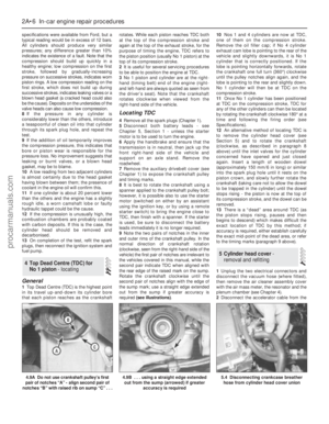 46
46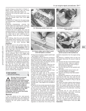 47
47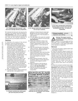 48
48 49
49 50
50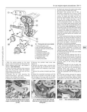 51
51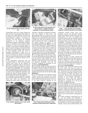 52
52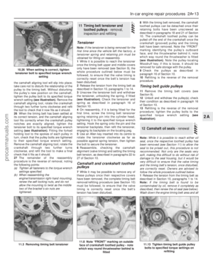 53
53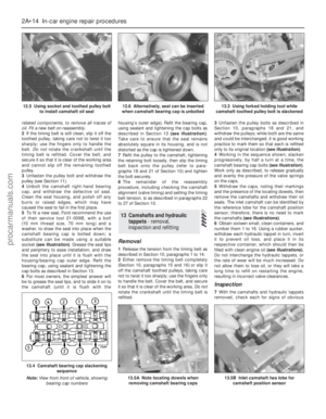 54
54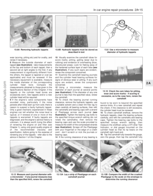 55
55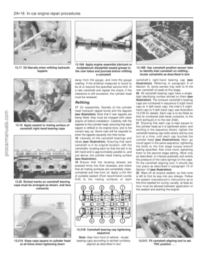 56
56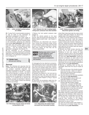 57
57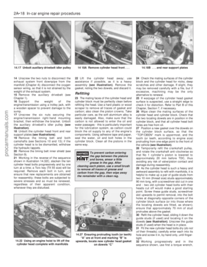 58
58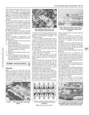 59
59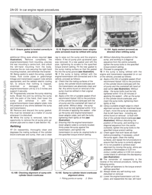 60
60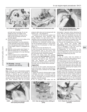 61
61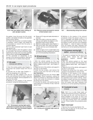 62
62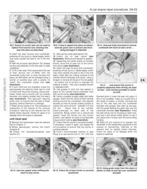 63
63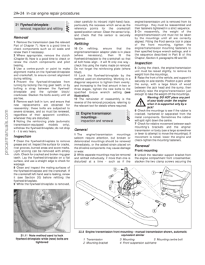 64
64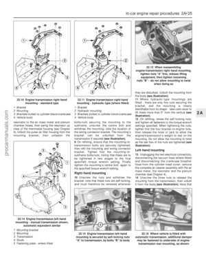 65
65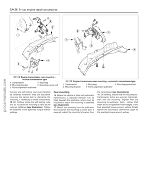 66
66 67
67 68
68 69
69 70
70 71
71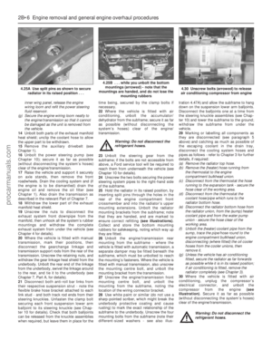 72
72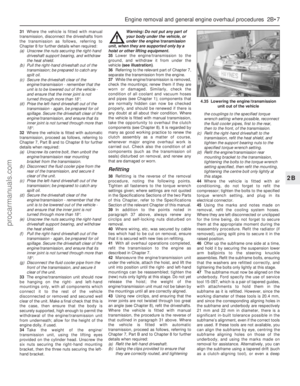 73
73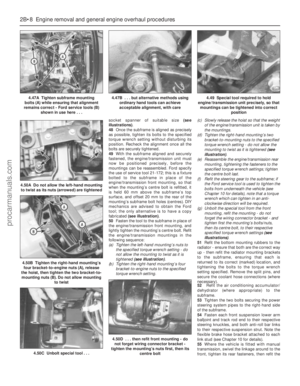 74
74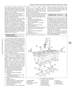 75
75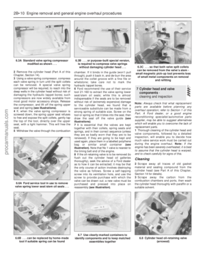 76
76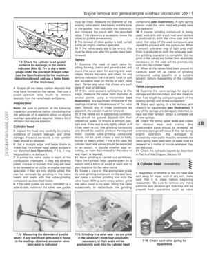 77
77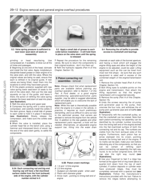 78
78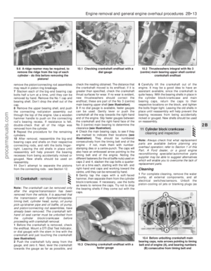 79
79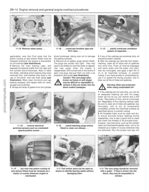 80
80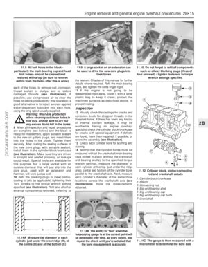 81
81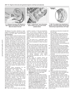 82
82 83
83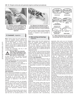 84
84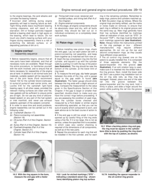 85
85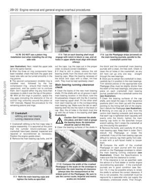 86
86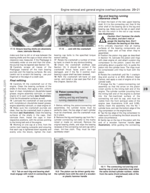 87
87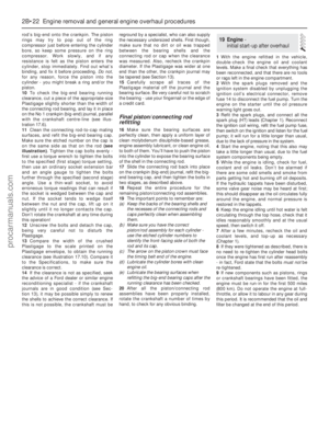 88
88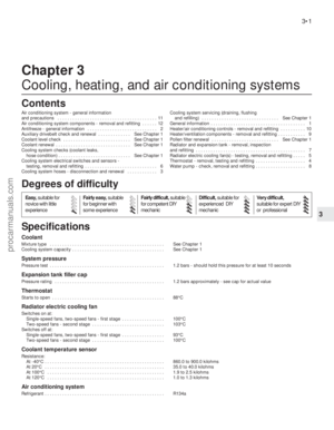 89
89 90
90 91
91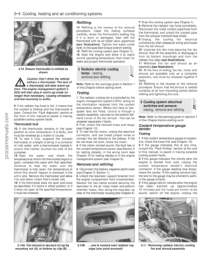 92
92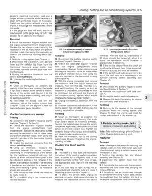 93
93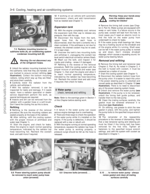 94
94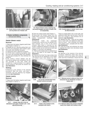 95
95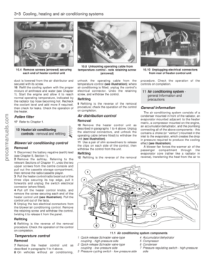 96
96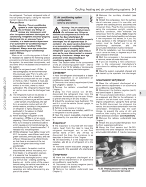 97
97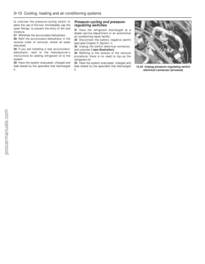 98
98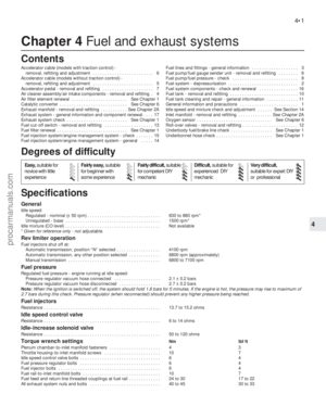 99
99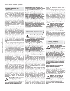 100
100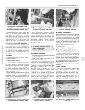 101
101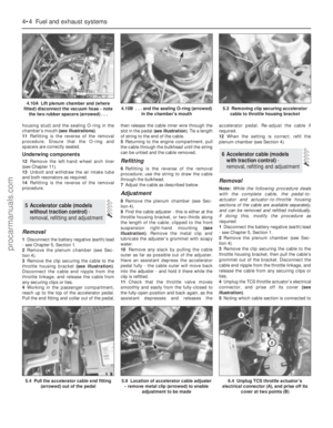 102
102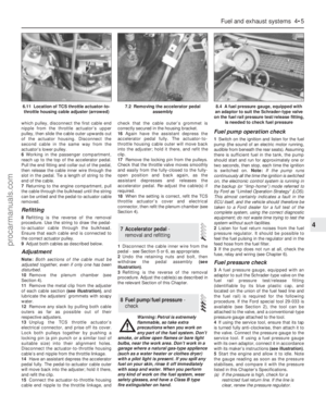 103
103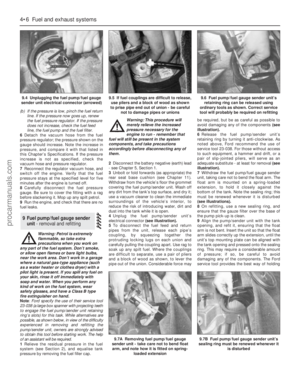 104
104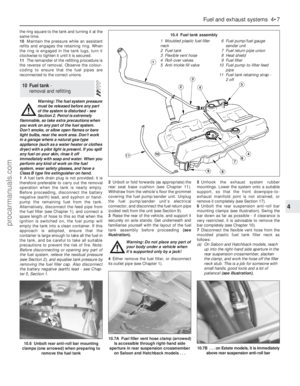 105
105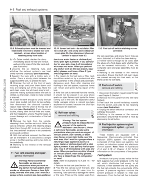 106
106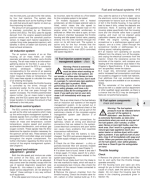 107
107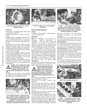 108
108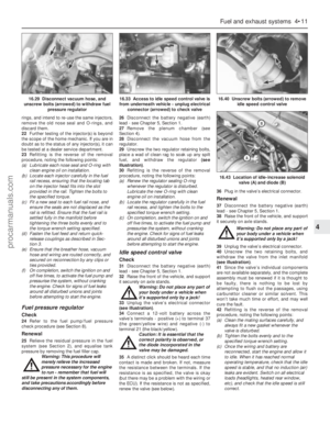 109
109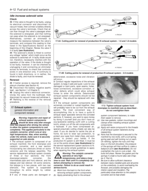 110
110 111
111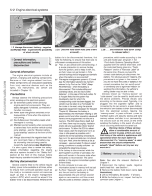 112
112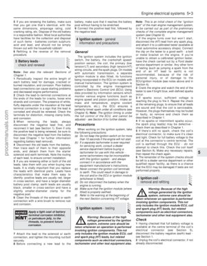 113
113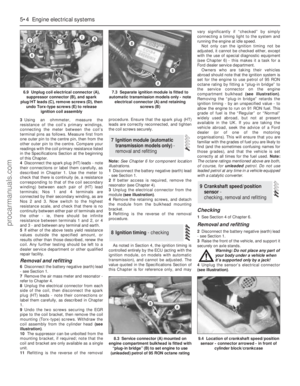 114
114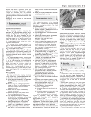 115
115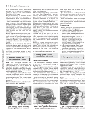 116
116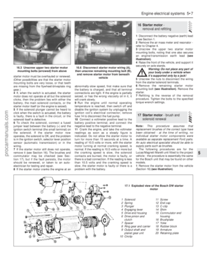 117
117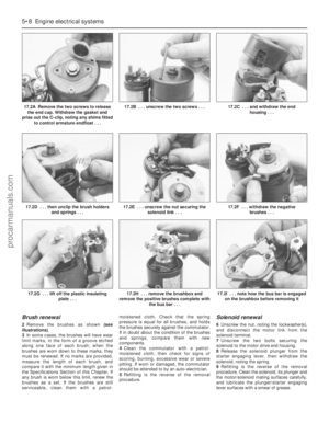 118
118 119
119 120
120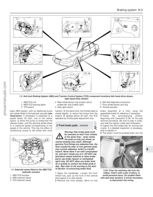 121
121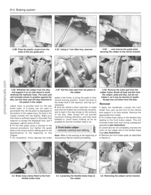 122
122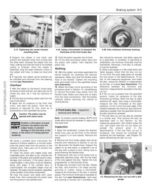 123
123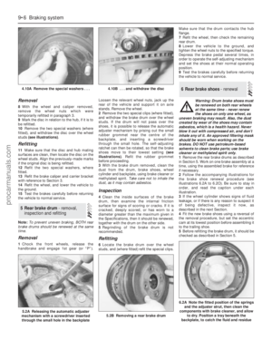 124
124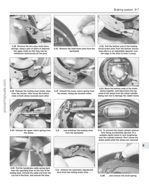 125
125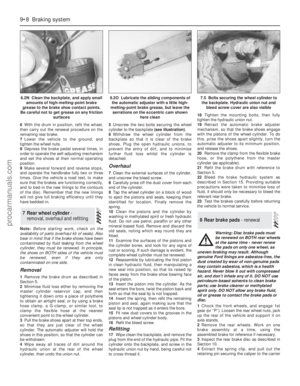 126
126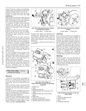 127
127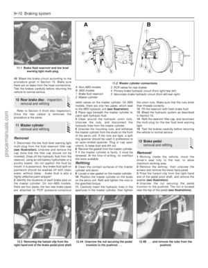 128
128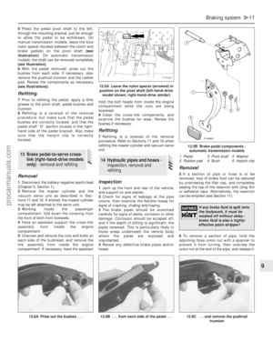 129
129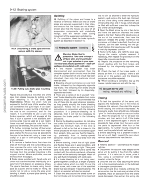 130
130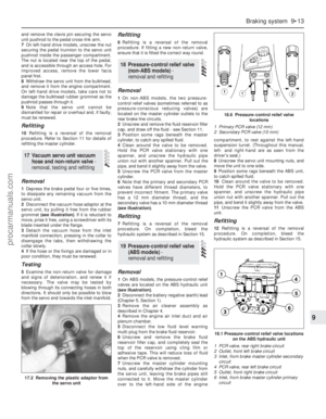 131
131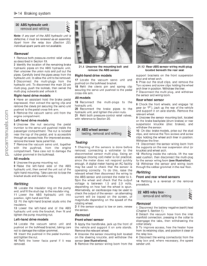 132
132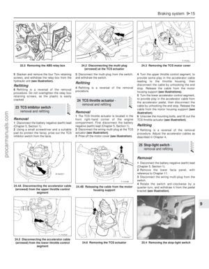 133
133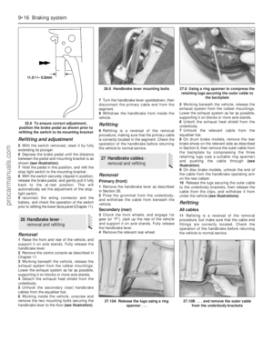 134
134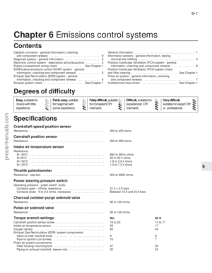 135
135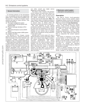 136
136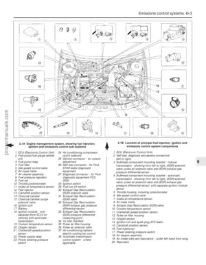 137
137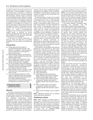 138
138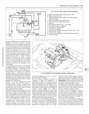 139
139 140
140 141
141 142
142 143
143 144
144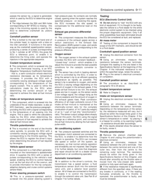 145
145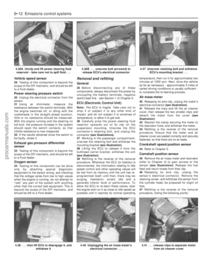 146
146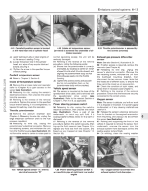 147
147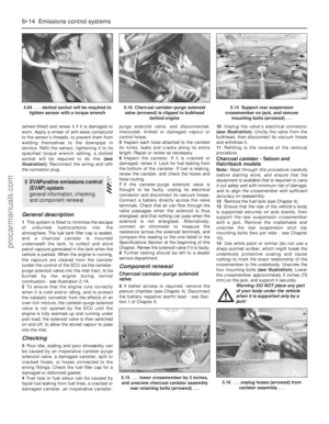 148
148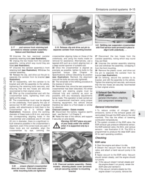 149
149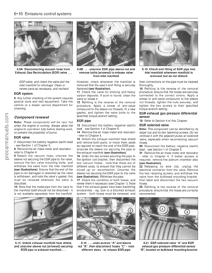 150
150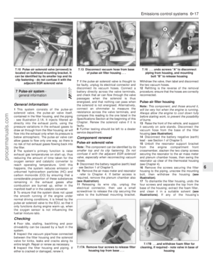 151
151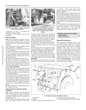 152
152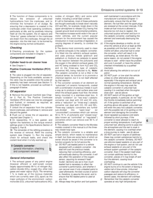 153
153 154
154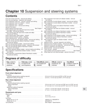 155
155 156
156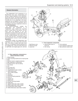 157
157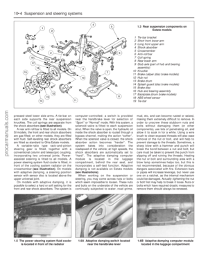 158
158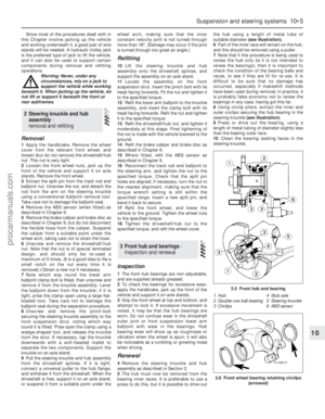 159
159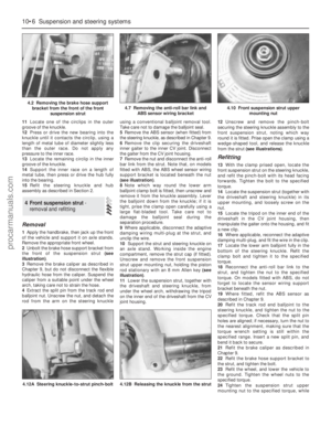 160
160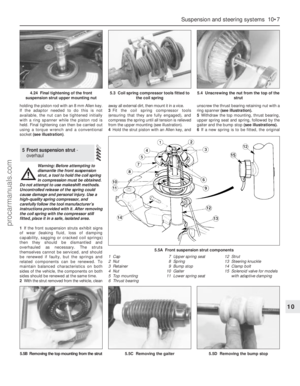 161
161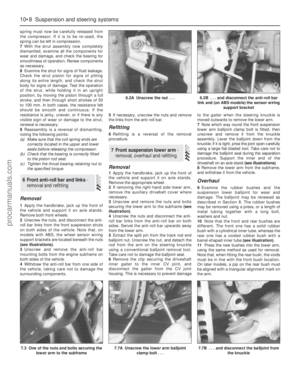 162
162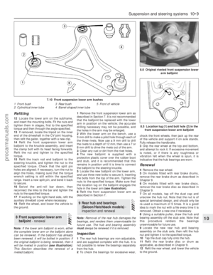 163
163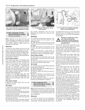 164
164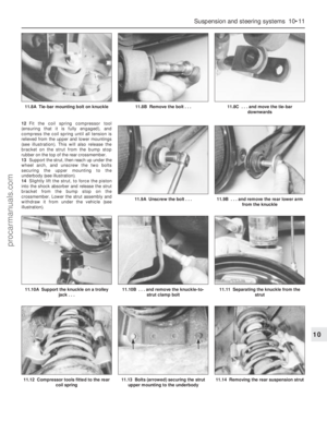 165
165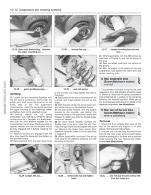 166
166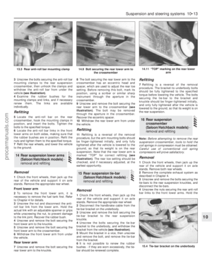 167
167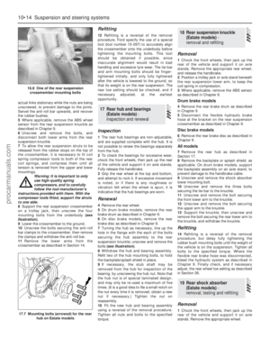 168
168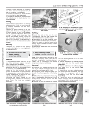 169
169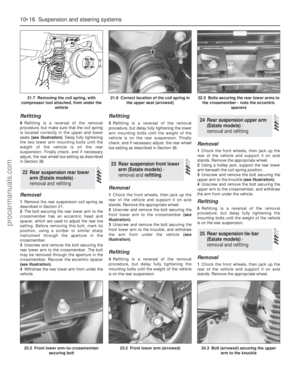 170
170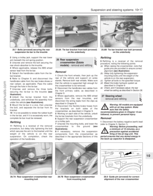 171
171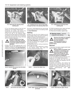 172
172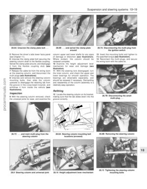 173
173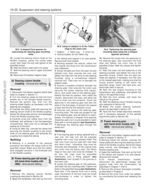 174
174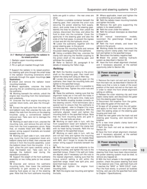 175
175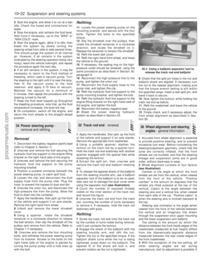 176
176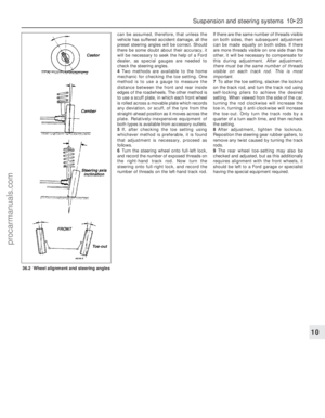 177
177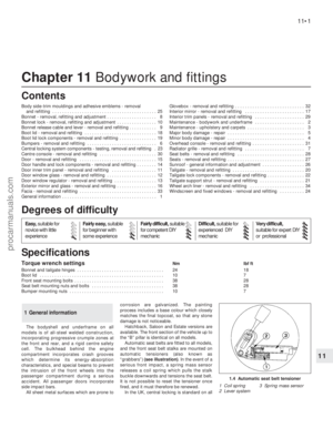 178
178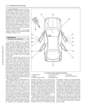 179
179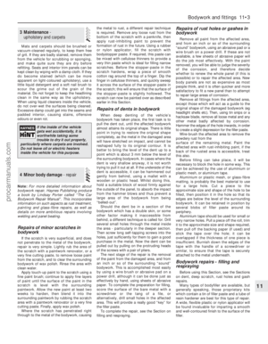 180
180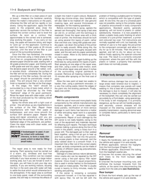 181
181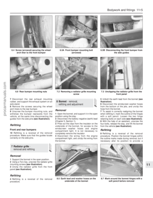 182
182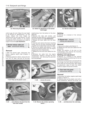 183
183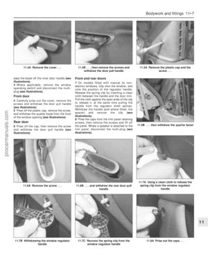 184
184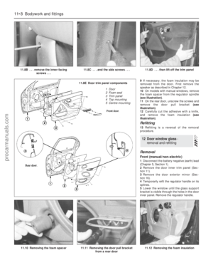 185
185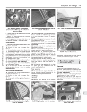 186
186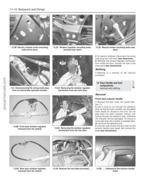 187
187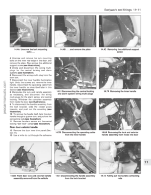 188
188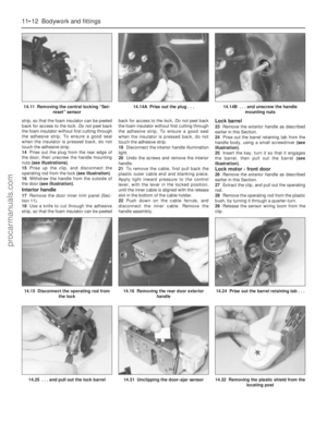 189
189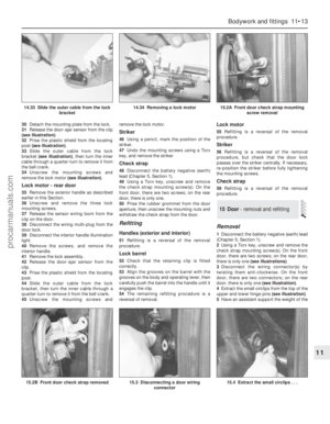 190
190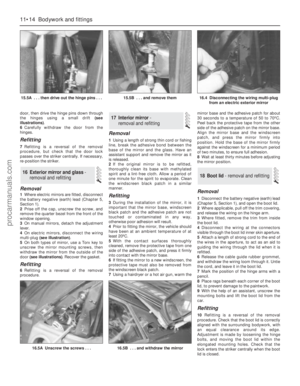 191
191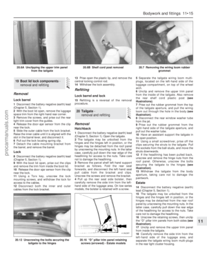 192
192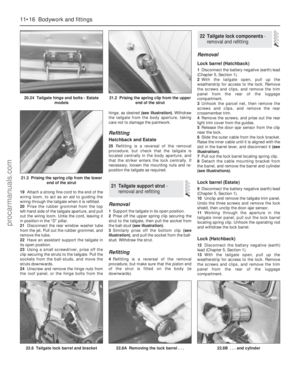 193
193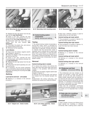 194
194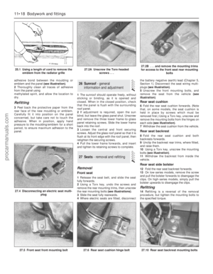 195
195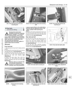 196
196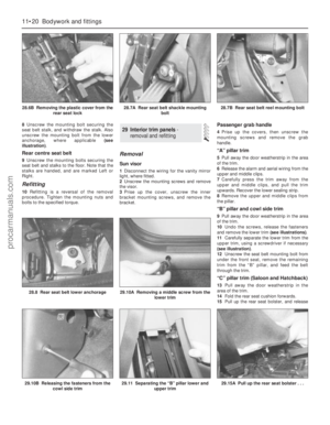 197
197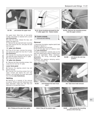 198
198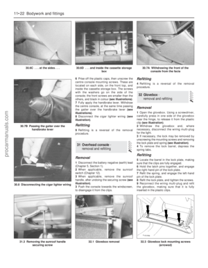 199
199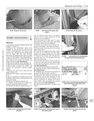 200
200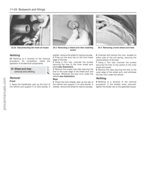 201
201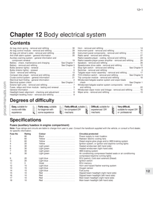 202
202 203
203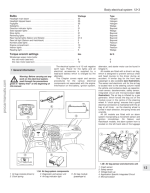 204
204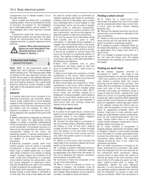 205
205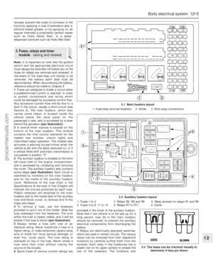 206
206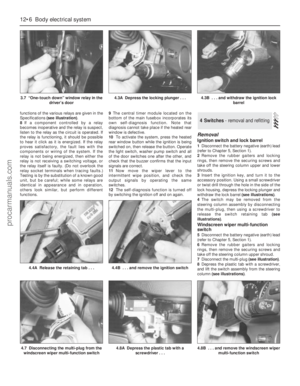 207
207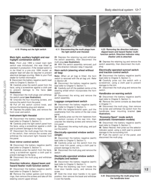 208
208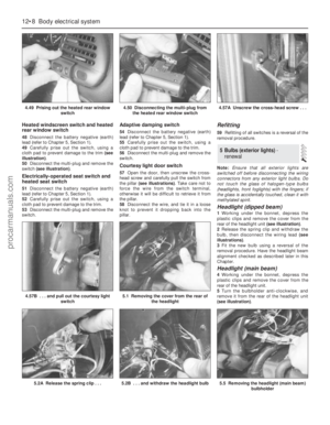 209
209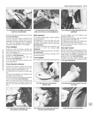 210
210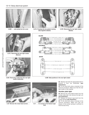 211
211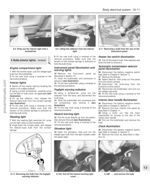 212
212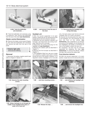 213
213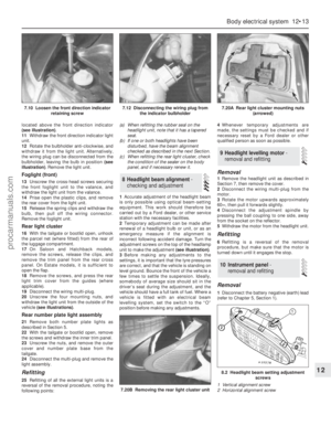 214
214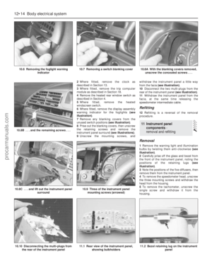 215
215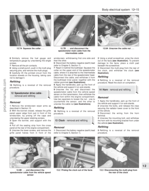 216
216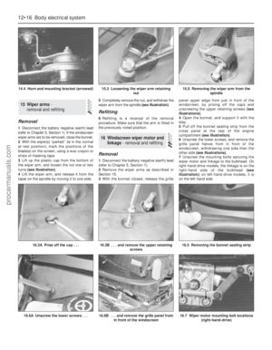 217
217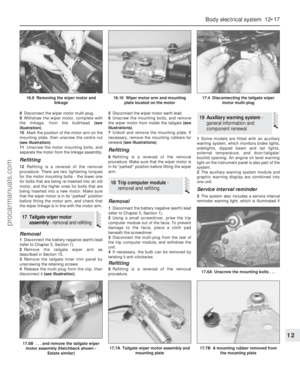 218
218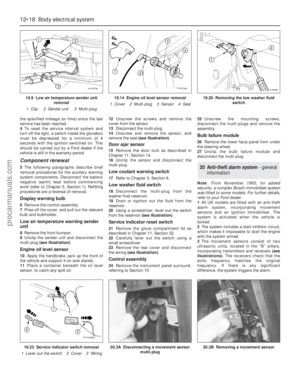 219
219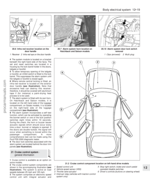 220
220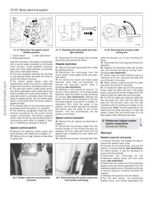 221
221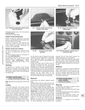 222
222 223
223 224
224 225
225 226
226 227
227 228
228 229
229 230
230 231
231 232
232 233
233 234
234 235
235 236
236 237
237 238
238 239
239 240
240 241
241 242
242 243
243 244
244 245
245 246
246 247
247 248
248 249
249 250
250 251
251 252
252 253
253 254
254 255
255 256
256 257
257 258
258 259
259 260
260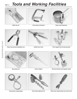 261
261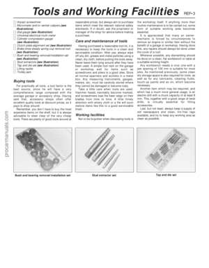 262
262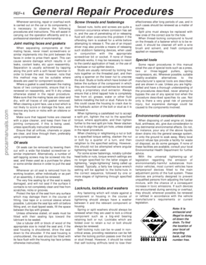 263
263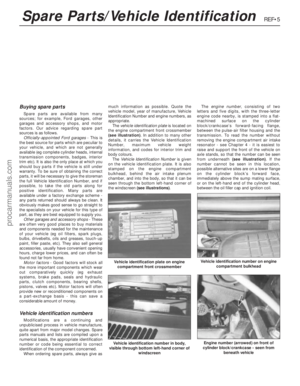 264
264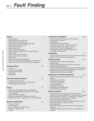 265
265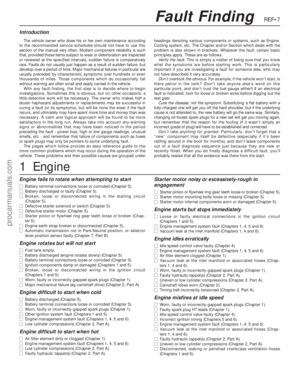 266
266 267
267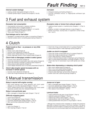 268
268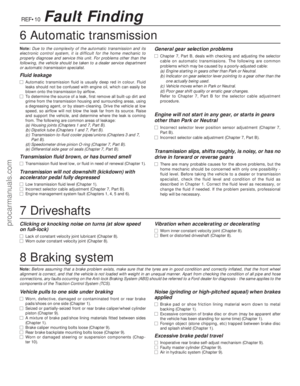 269
269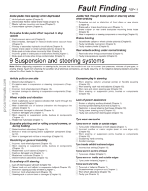 270
270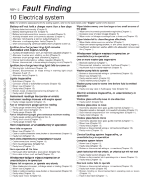 271
271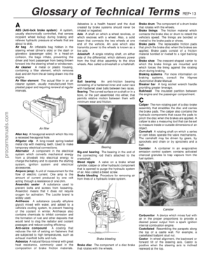 272
272 273
273 274
274 275
275 276
276 277
277 278
278