Page 105 of 279

the ring square to the tank and turning it at the
same time.
10Maintain the pressure while an assistant
refits and engages the retaining ring. When
the ring is engaged in the tank lugs, turn it
clockwise to tighten it until it is secured.
11The remainder of the refitting procedure is
the reverse of removal. Observe the colour-
coding to ensure that the fuel pipes are
reconnected to the correct unions.
Warning: The fuel system pressure
must be released before any part
of the system is disturbed - see
Section 2. Petrol is extremely
flammable, so take extra precautions when
you work on any part of the fuel system.
Don’t smoke, or allow open flames or bare
light bulbs, near the work area. Don’t work
in a garage where a natural gas-type
appliance (such as a water heater or clothes
dryer) with a pilot light is present. If you spill
any fuel on your skin, rinse it off
immediately with soap and water. When you
perform any kind of work on the fuel
system, wear safety glasses, and have a
Class B type fire extinguisher on hand.
1A fuel tank drain plug is not provided; it is
therefore preferable to carry out the removal
operation when the tank is nearly empty.
Before proceeding, disconnect the battery
negative (earth) lead, and syphon or hand-
pump the remaining fuel from the tank.
Alternatively, disconnect the feed pipe from
the fuel filter (see Chapter 1), and connect a
spare length of hose to this so that when the
ignition is switched on, the fuel pump will
empty the tank into a clean container. If this
approach is adopted, ensure that the
container is large enough to take all the fuel in
the tank, and be careful to take all suitable
precautions to prevent the risk of fire. Note:
Before disconnecting or opening any part of
the fuel system, relieve the residual pressure
(see Section 2), and equalise tank pressure by
removing the fuel filler cap. Also disconnect
the battery negative (earth) lead - see Chap-
ter 5, Section 1.2Unbolt or fold forwards (as appropriate) the
rear seat base cushion (see Chapter 11).
Withdraw from the vehicle’s floor the grommet
covering the fuel pump/sender unit. Unplug
the fuel pump/sender unit’s electrical
connector, and disconnect the fuel return pipe
(coded red) from the unit (see Section 9).
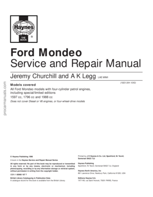
3Raise the rear of the vehicle, and support it
securely on axle stands. Get underneath and
familiarise yourself with the layout of the fuel
tank assembly before proceeding (see
illustration).
Warning: Do not place any part of
your body under a vehicle when
it’s supported only by a jack!
4Either remove the fuel filter, or disconnect
its outlet pipe (see Chapter 1).5Unhook the exhaust system rubber
mountings. Lower the system onto a suitable
support, so that the front downpipe-to-
exhaust manifold joint is not strained, or
remove it completely (see Section 17).
6Unbolt the rear suspension anti-roll bar
mounting clamps (see illustration). Swing the
bar down as far as possible - if clearance is
very restricted, it is advisable to remove the
bar completely (see Chapter 10).
7Disconnect the flexible vent hose from the
moulded plastic fuel tank filler neck as
follows:
(a) On Saloon and Hatchback models, reach
up into the right-hand side aperture in the
rear suspension crossmember, slacken
the clamp, and work the hose off the filler
neck stub. This is a job for someone with
small hands, good tools and a lot of
patience! (see illustration).
10 Fuel tank -
removal and refitting
Fuel and exhaust systems 4•7
4
10.6 Unbolt rear anti-roll bar mounting
clamps (one arrowed) when preparing to
remove the fuel tank10.7A Fuel filler vent hose clamp (arrowed)
is accessible through right-hand side
aperture in rear suspension crossmember
on Saloon and Hatchback models . . .
10.7B . . . on Estate models, it is immediately
above rear suspension anti-roll bar
10.4 Fuel tank assembly
1 Moulded plastic fuel filler
neck
2 Fuel tank
3 Flexible vent hose
4 Roll-over valves
5 Anti-trickle fill valve6 Fuel pump/fuel gauge
sender unit
7 Fuel return pipe union
8 Heat shield
9 Fuel filter
10 Fuel pump-to-filter feed
pipe
11 Fuel tank retaining strap -
2 off
procarmanuals.com
Page 106 of 279
 On Estate models, slacken the clamp
immediately above the rear anti-roll bar,
and work the hose off the filler neck stub
(see illustration).
8Unscrew the six retaining nuts, and
withdraw the exhau")
(b) On Estate models, slacken the clamp
immediately above the rear anti-roll bar,
and work the hose off the filler neck stub
(see illustration).
8Unscrew the six retaining nuts, and
withdraw the exhaust system’s rear heat
shield from the underbody (see illustration).
9Support the tank with a trolley jack or
similar. Place a sturdy plank between the
support and the tank, to protect the tank.
10Unscrew the bolt at the front of each
retaining strap, and pivot them down until
they are hanging out of the way. Note the
earth lead under the left-hand strap’s bolt -
clean the mating surfaces before the tank is
refitted, so that clean, metal-to-metal contact
is ensured.
11Lower the tank enough to unclip the fuel
return pipe (coded red) from its top surface,
then disconnect the charcoal canister’s
vapour hose from the union at the top rear of
the tank (see illustration). If you have any
doubts, clearly label the fuel lines and hoses,
and their respective unions. Plug the hoses, to
prevent leakage and contamination of the fuel
system.
12Remove the tank from the vehicle,
releasing it from the filler neck stub. While the
tank is removed, unhook the retaining straps
(twist them through 90° to do so), and check
that they and their locations in the underbody
are in good condition.
13With the fuel tank removed, the filler neck
can be withdrawn. It is secured by a single
screw in the filler opening, and by two bolts to
the underbody.
14Refitting is the reverse of the removal
procedure.
Warning: Petrol is extremely
flammable, so take extra
precautions when you work on
any part of the fuel system. Don’t
smoke, or allow open flames or bare light
bulbs, near the work area. Don’t work in a
garage where a natural gas-type appliance(such as a water heater or clothes dryer)
with a pilot light is present. If you spill any
fuel on your skin, rinse it off immediately
with soap and water. When you perform
any kind of work on the fuel system, wear
safety glasses, and have a Class B type
fire extinguisher on hand.
1Any repairs to the fuel tank or filler neck
should be carried out by a professional who
has experience in this critical and potentially-
dangerous work. Even after cleaning and
flushing of the fuel system, explosive fumes
can remain and ignite during repair of the
tank.
2If the fuel tank is removed from the vehicle,
it should not be placed in an area where
sparks or open flames could ignite the fumes
coming out of the tank. Be especially careful
inside garages where a natural gas-type
appliance is located, because the pilot light
could cause an explosion.
Warning: The fuel system
pressure must be released before
any part of the system is
disturbed - see Section 2. Petrol
is extremely flammable, so take extra
precautions when you work on any part of
the fuel system. Don’t smoke, or allow
open flames or bare light bulbs, near the
work area. Don’t work in a garage where a
natural gas-type appliance (such as a
water heater or clothes dryer) with a pilot
light is present. If you spill any fuel on your
skin, rinse it off immediately with soap and
water. When you perform any kind of work
on the fuel system, wear safety glasses,
and have a Class B type fire extinguisher
on hand.
Note: Refer to illustrations 10.4 and 10.11 for
details.
1Remove the fuel tank (see Section 10).
2Prise the two valves out of the tank, and
remove the anti-trickle fill valve from its
mounting. Take care not to damage the valves
or the tank. Prise out the rubber seals fromthe tank openings, and renew then if they are
worn, distorted, or if either has been leaking.
3If either valve is thought to be faulty, seek
the advice of a Ford dealer as to whether they
can be renewed individually. If not, the
complete valve and pipe assembly must be
renewed.
4Refitting is the reverse of the removal
procedure. Ensure that both roll-over valves
are pressed securely into their seals, so that
there can be no fuel leaks.
1Disconnect the battery negative (earth) lead
- see Chapter 5, Section 1.
2Remove the trim panel from the left-hand
footwell.
3Peel back the sound-insulating material
from the switch, and undo its two retaining
screws (see illustration).
4Unplug the switch electrical connector, and
withdraw the switch.
5Refitting is the reverse of the removal
procedure. Ensure that the switch is reset by
depressing its red button.
These models are equipped with a
Sequential Electronically-controlled Fuel
Injection (SEFI) system. The system is
composed of three basic sub-systems: fuel
system, air induction system and electronic
control system. Note:Refer to illustrations
2.1A and 2.1B of Chapter 6 for further
information on the components of the system.
Fuel system
An electric fuel pump located inside the fuel
tank supplies fuel under pressure to the fuel
rail, which distributes fuel evenly to all
injectors. A filter between the fuel pump and
the fuel rail protects the components of the
system. A pressure regulator controls the
system pressure in relation to inlet tract
depression. From the fuel rail, fuel is injected
14 Fuel injection system/engine
management system - general
information
13 Fuel cut-off switch -
removal and refitting
12 Roll-over valves -
removal and refitting
11 Fuel tank cleaning and repair -
general information
4•8 Fuel and exhaust systems
10.8 Exhaust system must be lowered and
heat shield removed to enable fuel tank
removal - arrows show location of
retaining strap front bolts10.11 Lower fuel tank - do not distort filler
neck stub (A) - and unclip (red-coded) fuel
return pipe (B), then disconnect charcoal
canister’s vapour hose (C)13.3 Fuel cut-off switch retaining screws
(arrowed)
procarmanuals.com
Page 107 of 279
 fuel around each injector on start-up,
thus improv")
into the inlet ports, just above the inlet valves,
by four fuel injectors. The system also
includes features such as the flushing of fresh
(ie, cold) fuel around each injector on start-up,
thus improving hot starts.
The amount of fuel supplied by the injectors
is precisely controlled by an Electronic
Control Unit (ECU). The ECU uses the signals
derived from the engine speed/crankshaft
position sensor and the camshaft position
sensor, to trigger each injector separately in
cylinder firing order (sequential injection), with
benefits in terms of better fuel economy and
lower exhaust emissions.
Air induction system
The air system consists of an air filter
housing, an air mass meter, an intake
resonator and plenum chamber, and a throttle
housing. The air mass meter is an information-
gathering device for the ECU; it uses a “hot-
wire” system to send the ECU a constantly-
varying (analogue) voltage signal
corresponding to the volume of air passing
into the engine. Another sensor in the air mass
meter measures intake air temperature. The
ECU uses these signals to calculate the mass
of air entering the engine.
The throttle valve inside the throttle housing
is controlled by the driver, through the
accelerator pedal. As the valve opens, the
amount of air that can pass through the
system increases. The throttle potentiometer
opens further, the air mass meter’s signal
alters, and the ECU opens each injector for a
longer duration, to increase the amount of fuel
delivered to the inlet ports.
Electronic control system
The ECU controls the fuel injection system,
as well as the other sub-systems which make
up the entire engine management system. It
receives signals from a number of information
sensors, which monitor such variables as
intake air mass and temperature, coolant
temperature, engine speed and position,
acceleration/deceleration, and exhaust gas
oxygen content. These signals help the ECU
determine the injection duration necessary for
the optimum air/fuel ratio. These sensors and
associated ECU-controlled relays are located
throughout the engine compartment. For
further information regarding the ECU and its
control of the engine management system,
see Chapter 6.
Idle speed and mixture
adjustment - general
Both the idle speed and mixture are under
the control of the ECU, and cannot be
adjusted. Not only can they not be adjusted,
they cannot even be checked, except with the
use of special diagnostic equipment (see
Chapter 6) - this makes it a task for a Ford
dealer service department. Do notattempt to
“adjust” these settings in any way without
such equipment.
If the idle speed and mixture are thought tobe incorrect, take the vehicle to a Ford dealer
for the complete system to be tested.
On models equipped with a heated
windscreen, an idle-increase solenoid valve is
fitted, which raises the idle speed to
compensate for the increased load on the
engine when the heated windscreen is
switched on. When the valve is open, air from
the plenum chamber bypasses the throttle
housing and idle speed control valve, passing
directly into the inlet manifold through the
union on its left-hand end. The system is
active only for the four minutes that the
heated windscreen circuit is live, and is
supplementary to the main (ECU-controlled)
idle speed regulation.
Warning: Petrol is extremely
flammable, so extra precautions
must be taken when working on
any part of the fuel system. Do
not smoke, or allow open flames or bare
light bulbs, near the work area. Don’t work
in a garage if a natural gas-type appliance
with a pilot light is present. While
performing any work on the fuel system,
wear safety glasses, and have a dry
chemical (Class B) fire extinguisher on
hand. If you spill any fuel on your skin,
rinse it off immediately with soap and
water.
Note: This is an initial check of the fuel delivery
and air induction sub-systems of the engine
management system, to be carried out in
conjunction with the operational check of the
fuel pump (see Section 8), and as part of the
preliminary checks of the complete engine
management system (see Section 3 of
Chapter 6).
1Check the earth wire connections for
tightness. Check all wiring and electrical
connectors that are related to the system.
Loose electrical connectors and poor earths
can cause many problems that resemble
more serious malfunctions.
2Check to see that the battery is fully-
charged. The ECU and sensors depend on an
accurate supply voltage to properly meter the
fuel.
3Check the air filter element - a dirty or
partially-blocked filter will severely impede
performance and economy (see Chapter 1).
4If a blown fuse is found, renew it and see if
it blows again. If it does, search for a short-
circuited wire in the harness related to the
system (see Chapter 6).
5Check the air intake duct from the intake to
the inlet manifold for leaks, which will result in
an excessively-lean mixture. Also check the
condition of the vacuum hoses connected to
the inlet manifold.
6Remove the plenum chamber from the
throttle housing. Check the throttle valve for
dirt, carbon or other residue build-up. If it’sdirty, seek the advice of a Ford dealer - since
the electronic control system is designed to
compensate for factors such as the build-up
of dirt in the throttle housing, it may well be
best to leave it dirty, unless the deposits are
extensive. Note: A warning label on the
housing states specifically that the housing
bore and the throttle valve have a special
coating, and must not be cleaned using
carburettor cleaner, as this may damage it.
7With the engine running, place a
screwdriver or a stethoscope against each
injector, one at a time. Listen through the
screwdriver handle or stethoscope for a
clicking sound, indicating operation.
8If an injector isn’t operating (or sounds
different from the others), turn off the engine,
and unplug the electrical connector from the
injector. Check the resistance across the
terminals of the injector, and compare your
reading with the resistance value listed in this
Chapter’s Specifications. If the resistance
isn’t as specified, renew the injector.
9A rough idle, diminished performance
and/or increased fuel consumption could also
be caused by clogged or fouled fuel injectors.
Fuel additives that can sometimes clean
fouled injectors are available at car accessory
shops.
10The remainder of the system checks
should be left to a dealer service department
or other qualified repair specialist, as there is
a chance that the ECU may be damaged if
tests are not performed properly.
Warning: The fuel system
pressure must be released before
any part of the system is
disturbed - see Section 2. Petrol
is extremely flammable, so take extra
precautions when you work on any part of
the fuel system. Don’t smoke, or allow
open flames or bare light bulbs, near the
work area. Don’t work in a garage where a
natural gas-type appliance (such as a
water heater or clothes dryer) with a pilot
light is present. If you spill any fuel on your
skin, rinse it off immediately with soap and
water. When you perform any kind of work
on the fuel system, wear safety glasses,
and have a Class B type fire extinguisher
on hand.
Throttle housing
Check
1Remove the plenum chamber (see Sec-
tion 4), and verify that the throttle linkage
operates smoothly.
2If the housing bore and valve are dirty
enough for you to think that this might be the
cause of a fault, seek the advice of a Ford
dealer. Do notclean the housing (see the
notes in the checking procedure given in
Section 15).
16 Fuel system components-
check and renewal
15 Fuel injection system/engine
management system - check
Fuel and exhaust systems 4•9
4
procarmanuals.com
Page 108 of 279
 lead
- see Chapter 5, Section 1.
4Remove the plenum chamber (see Sec-
tion 4).
5Disconnect the accelerator cable from the
throttle linkage (see Section")
Renewal
3Disconnect the battery negative (earth) lead
- see Chapter 5, Section 1.
4Remove the plenum chamber (see Sec-
tion 4).
5Disconnect the accelerator cable from the
throttle linkage (see Section 5 or 6, as
appropriate). Where fitted, also disconnect
the cruise control actuator cable (see Chap-
ter 12).
6Releasing its wire clip, unplug the large
electrical connector (next to the fuel pressure
regulator). Similarly release and unplug the
throttle potentiometer’s electrical connector.
7Clearly label, then detach, all vacuum hoses
from the throttle housing.
8Remove the throttle housing mounting
screws (see illustration), then detach the
throttle housing and gasket from the inlet
manifold. Discard the gasket - this must be
renewed whenever it is disturbed.
9Using a soft brush and carburettor cleaner,
thoroughly clean the exterior of the throttle
housing, then blow out all passages with
compressed air.
Caution: Do not clean the throttle
housing’s bore, the throttle valve,
or the potentiometer, either by
scraping or with a solvent. Just
wipe them over carefully with a clean soft
cloth.
10Refitting is the reverse of the removal
procedure. Fit a new gasket, and tighten the
housing screws to the specified torque.
Fuel rail and injectors
Check
11Refer to the procedure in the fuel system
check (see Section 15).
Renewal
Note:For simplicity, and to ensure the
necessary absolute cleanliness on
reassembly, the following procedure
describes the removal of the fuel rail
assembly, complete with the injectors and
pressure regulator, so that the injectors can be
serviced individually on a clean work surface.
It is also possible to remove and refit an
individual injector once the fuel system has
been depressurised and the battery has been
disconnected. If this approach is followed,
read through the complete procedure, and
work as described in the relevant paragraphs,
depending on the amount of preliminary
dismantling required. Be careful not to allow
any dirt to enter the system (see
illustrations).
12Relieve the residual pressure in the fuel
system (see Section 2), and equalise tank
pressure by removing the fuel filler cap.
Warning: This procedure will
merely relieve the increased
pressure necessary for the
engine to run - remember that
fuel will still be present in the system
components, and take precautions
accordingly before disconnecting any of
them.
13Disconnect the battery negative (earth)
lead - see Chapter 5, Section 1.
14Remove the plenum chamber (see
Section 4).
15If the additional clearance is required,
disconnect the accelerator cable from the
throttle linkage (see Section 5 or 6, as
appropriate). Where fitted, also disconnect
the cruise control actuator cable (see Chap-
ter 12).
16Releasing the wire clips, unplug the four
fuel injector electrical connectors.
17Disconnect the fuel feed and return lines
at the quick-release couplings next to the
braking system vacuum servo unit, then
unclip the fuel hoses from the inlet manifold;
use rag to soak up any spilt fuel. Note:Do not
disturb the threaded couplings at the fuel rail
unions unless absolutely necessary; these aresealed at the factory. The quick-release
couplings will suffice for all normal service
operations.
18Disconnect the crankcase breather hose
from the cylinder head cover union, and the
vacuum hose from the fuel pressure regulator
(see illustration).
19Unscrew the three bolts securing the fuel
rail, and withdraw the rail, carefully prising it
out of the inlet manifold, and draining any
remaining fuel into a suitable clean container
(see illustrations). Note the seals between
the rail noses and the manifold; these must be
renewed whenever the rail is removed.
20Clamping the rail carefully in a vice fitted
with soft jaws, unscrew the two bolts securing
each injector, and withdraw the injectors.
Place each in a clean, clearly-labelled storage
container.
21If you are renewing the injector(s), discard
the old injector, the nose seal and the O-rings.
If you are simply renewing leaking injector O-
4•10 Fuel and exhaust systems
16.8 Undo screws (arrowed) to remove
throttle housing16.12A Fuel injectors can be unbolted
(arrowed) . . .16.12B . . . and removed individually if
required, but it is better to remove them
with the fuel rail, if servicing is necessary.
O-ring seals (arrowed) must be renewed
whenever injector is removed
16.18 Injector removal - disconnect fuel
lines at quick-release couplings (A), unclip
hoses (B), disconnect vacuum hose from
regulator (C), unplug electrical
connectors (D) - three of four shown - and
disconnect breather hose from union (E)
16.19A Unscrew bolts (arrowed) . . .
16.19B . . . and withdraw fuel rail with
injectors and pressure regulator - renew
nose seals (arrowed) whenever rail is
disturbed
procarmanuals.com
Page 109 of 279
 is beyond
the scope of the home mechanic. If you are in
dou")
rings, and intend to re-use the same injectors,
remove the old nose seal and O-rings, and
discard them.
22Further testing of the injector(s) is beyond
the scope of the home mechanic. If you are in
doubt as to the status of any injector(s), it can
be tested at a dealer service department.
23Refitting is the reverse of the removal
procedure, noting the following points:
(a) Lubricate each nose seal and O-ring with
clean engine oil on installation.
(b) Locate each injector carefully in the fuel
rail recess, ensuring that the locating tab
on the injector head fits into the slot
provided in the rail. Tighten the bolts to
the specified torque.
(c) Fit a new seal to each fuel rail nose, and
ensure the seals are not displaced as the
rail is refitted. Ensure that the fuel rail is
settled fully in the manifold before
tightening the three bolts evenly and to
the torque wrench setting specified.
(d) Fasten the fuel feed and return quick-
release couplings as described in Sec-
tion 3.
(e) Ensure that the breather hose, vacuum
hose and wiring are routed correctly, and
secured on reconnection by any clips or
ties provided.
(f) On completion, switch the ignition on and
off five times, to activate the fuel pump and
pressurise the system, without cranking
the engine. Check for signs of fuel leaks
around all disturbed unions and joints
before attempting to start the engine.
Fuel pressure regulator
Check
24Refer to the fuel pump/fuel pressure
check procedure (see Section 8).
Renewal
25Relieve the residual pressure in the fuel
system (see Section 2), and equalise tank
pressure by removing the fuel filler cap.
Warning: This procedure will
merely relieve the increased
pressure necessary for the engine
to run - remember that fuel will
still be present in the system components,
and take precautions accordingly before
disconnecting any of them.26Disconnect the battery negative (earth)
lead - see Chapter 5, Section 1.
27Remove the plenum chamber (see
Section 4).
28Disconnect the vacuum hose from the
regulator.
29Unscrew the two regulator retaining bolts,
place a wad of clean rag to soak up any spilt
fuel, and withdraw the regulator (see
illustration).
30Refitting is the reverse of the removal
procedure, noting the following points:
(a) Renew the regulator sealing O-ring
whenever the regulator is disturbed.
Lubricate the new O-ring with clean
engine oil on installation.
(b) Locate the regulator carefully in the fuel
rail recess, and tighten the bolts to the
specified torque wrench setting.
(c) On completion, switch the ignition on and
off five times, to activate the fuel pump and
pressurise the system, without cranking
the engine. Check for signs of fuel leaks
around all disturbed unions and joints
before attempting to start the engine.
Idle speed control valve
Check
31Disconnect the battery negative (earth)
lead - see Chapter 5, Section 1.
32Raise the front of the vehicle, and support
it securely on axle stands.
Warning: Do not place any part of
your body under a vehicle when
it’s supported only by a jack!
33Unplug the valve’s electrical connector
(see illustration).
34Connect a 12-volt battery across the
valve’s terminals - positive (+) to terminal 37
(the green/yellow wire) and negative (-) to
terminal 21 (the black/yellow).
Caution: It is essential that the
correct polarity is observed, or
the diode incorporated in the
valve may be damaged.
35A distinct click should be heard each time
contact is made and broken. If not, measure
the resistance between the terminals. If the
resistance is as specified, the valve is okay
(but there may be a problem with the wiring or
the ECU). If the resistance is not as specified,
renew the valve (see below).36Plug in the valve’s electrical connector.
Renewal
37Disconnect the battery negative (earth)
lead - see Chapter 5, Section 1.
38Raise the front of the vehicle, and support
it securely on axle stands.
Warning: Do not place any part of
your body under a vehicle when
it’s supported only by a jack!
39Unplug the valve’s electrical connector.
40Unscrew the two retaining bolts, and
withdraw the valve from the inlet manifold
(see illustration).
41Since the valve’s individual components
are not available separately, and the complete
assembly must be renewed if it is thought to
be faulty, there is nothing to be lost by
attempting to flush out the passages, using
carburettor cleaner or similar solvent. This
won’t take much time or effort, and may well
cure the fault.
42Refitting is the reverse of the removal
procedure, noting the following points:
(a) Clean the mating surfaces carefully, and
always fit a new gasket whenever the
valve is disturbed.
(b) Tighten the bolts evenly and to the
specified torque wrench setting.
(c) Once the wiring and battery are
reconnected, start the engine and allow it
to idle. When it has reached normal
operating temperature, check that the idle
speed is stable, and that no induction (air)
leaks are evident. Switch on all electrical
loads (headlights, heated rear window,
etc), and check that the idle speed is still
correct.
Fuel and exhaust systems 4•11
4
16.43 Location of idle-increase solenoid
valve (A) and diode (B)
16.29 Disconnect vacuum hose, and
unscrew bolts (arrowed) to withdraw fuel
pressure regulator16.33 Access to idle speed control valve is
from underneath vehicle - unplug electrical
connector (arrowed) to check valve16.40 Unscrew bolts (arrowed) to remove
idle speed control valve
procarmanuals.com
Page 110 of 279

Idle-increase solenoid valve
Check
43If this valve is thought to be faulty, unplug
its electrical connector and disconnect its
vacuum hoses, then connect a battery directly
across the valve’s terminals. Check that air
can flow through the valve’s passages when
the solenoid is energised, and that nothing
can pass when the solenoid is not energised.
Alternatively, connect an ohmmeter to
measure the resistance between the valve’s
terminals, and compare this reading to that
listed in the Specifications Section at the
beginning of this Chapter. Renew the valve if
it is faulty (see illustration).
44The solenoid’s diode is fitted to control
any voltage “spikes” which might occur as the
solenoid is switched off. A faulty diode would
not, therefore, necessarily interfere with the
operation of the valve. If the diode is thought
to be faulty, however, it can be checked by
unplugging it and connecting an ohmmeter
across its terminals, to check that continuity
exists in one direction only. If continuity is
found in both directions, or in neither, the
diode is faulty, and must be renewed.
Renewal
45If better access is required, remove the
plenum chamber (see Section 4).
46Disconnect the battery negative (earth)
lead - see Section 1 of Chapter 5.
46Unplug the valve’s electrical connector.
Unclip the valve from the bulkhead, then
disconnect its vacuum hoses and withdraw it.
47Refitting is the reverse of the removal
procedure.
Warning: Inspection and repair of
exhaust system components
should be done only after enough
time has elapsed after driving the vehicle
to allow the system components to cool
completely. This applies particularly to the
catalytic converter, which runs at very
high temperatures. Also, when working
under the vehicle, make sure it is securely
supported on axle stands.
1The exhaust system is composed of an
exhaust manifold, the front downpipe and
catalytic converter, and a rear section
incorporating two silencers (three on some
versions) and the tailpipe assembly. The
service replacement exhaust system consists
of three or four sections: the front
downpipe/catalytic converter, the
intermediate pipe and front silencer, and the
tailpipe and rear silencer. On some versions,
the tailpipe is in two pieces, with two rear
silencers. The system is suspended
throughout its entire length by rubber
mountings.
2If any of these parts are damaged ordeteriorated, excessive noise and vibration
will occur.
3Conduct regular inspections of the exhaust
system, to keep it safe and quiet. Look for any
damaged or bent parts, open seams, holes,
loose connections, excessive corrosion, or
other defects which could allow exhaust
fumes to enter the vehicle. Deteriorated
exhaust system components should not be
repaired - they should be replaced with new
parts.
4If the exhaust system components are
extremely corroded or rusted together, they
will probably have to be cut from the exhaust
system. The most convenient way of
accomplishing this is to have a quick-fit
exhaust repair specialist remove the corroded
sections. If, however, you want to save money
by doing it yourself (and you don’t have an
oxy/acetylene welding outfit with a cutting
torch), simply cut off the old components with
a hacksaw. If you have compressed air,
special pneumatic cutting chisels can also be
used. If you do decide to tackle the job at
home, be sure to wear eye protection, to
protect your eyes from metal chips, and work
gloves, to protect your hands. If the
production-fit system is still fitted, it must be
cut at the points shown (see illustrations) for
the service-replacement system sections to fit.
5Here are some simple guidelines to apply
when repairing the exhaust system:
Warning: The catalytic converter
operates at very high
temperatures, and takes a long
time to cool. Wait until it’s completely cool
before attempting to remove the
converter. Failure to do so could result in
serious burns.
(a) Work from the back to the front when
removing exhaust system components.
(b) Apply penetrating fluid to the exhaustsystem component fasteners, to make
them easier to remove.
(c) Use new gaskets, rubber mountings and
clamps when installing exhaust system
components.
(d) Apply anti-seize compound to the threads
of all exhaust system fasteners during
reassembly.
(e) Note that the downpipe is secured to the
manifold by two bolts, with a coil spring,
spring seat and self-locking nut on each.
On refitting, tighten the nuts until they
stop on the bolt shoulders; the pressure
of the springs will then suffice to make a
leakproof joint (see illustration). Do not
overtighten the nuts to cure a leak - the
bolts will shear. Renew the gasket and the
springs if a leak is found (also see Chap-
ter 2, Part A).
(f) Be sure to allow sufficient clearance
between newly-installed parts and all points
on the underbody, to avoid overheating the
floorpan, and possibly damaging the
interior carpet and insulation. Pay
particularly close attention to the catalytic
converter and its heat shield.
17 Exhaust system -
general information and
component renewal
4•12 Fuel and exhaust systems
17.4A Cutting point for renewal of production-fit exhaust system - 1.6 and 1.8 models
17.4B Cutting points for renewal of production-fit exhaust system - 2.0 models
17.5 Tighten exhaust system front
downpipe-to-manifold nuts as described -
do not overtighten them
procarmanuals.com
Page 111 of 279

Chapter 5 Engine electrical systems
Alternator - removal and refitting . . . . . . . . . . . . . . . . . . . . . . . . . . . 12
Alternator brushes and voltage regulator - renewal . . . . . . . . . . . . . 13
Auxiliary drivebelt check and renewal . . . . . . . . . . . . . See Chapter 1
Battery - removal and refitting . . . . . . . . . . . . . . . . . . . . . . . . . . . . . 2
Battery check, maintenance and charging . . . . . . . . . See Chapter 1
Battery leads - check and renewal . . . . . . . . . . . . . . . . . . . . . . . . . . 3
Charging system - general information and precautions . . . . . . . . . 10
Charging system - testing . . . . . . . . . . . . . . . . . . . . . . . . . . . . . . . . . 11
Crankshaft speed/position sensor - checking, removal and refitting 9
Electronic control system - information and
fault diagnosis . . . . . . . . . . . . . . . . . . . . . . . . . . . . . See Chapter 6
Electronic Control Unit (ECU) and system information
sensors - general information . . . . . . . . . . . . . . . . . See Chapter 6Engine compartment wiring check . . . . . . . . . . . . . . . See Chapter 1
General information, precautions and battery disconnection . . . . . . 1
Ignition coil - removal and refitting . . . . . . . . . . . . . . . . . . . . . . . . . . 6
Ignition module (automatic transmission models only) -
removal and refitting . . . . . . . . . . . . . . . . . . . . . . . . . . . . . . . . . . . 7
Ignition system - general information and precautions . . . . . . . . . . . 4
Ignition system - testing . . . . . . . . . . . . . . . . . . . . . . . . . . . . . . . . . . 5
Ignition timing - checking . . . . . . . . . . . . . . . . . . . . . . . . . . . . . . . . . 8
Spark plug renewal and HT lead check . . . . . . . . . . . . See Chapter 1
Starter motor - brush and solenoid renewal . . . . . . . . . . . . . . . . . . . 17
Starter motor - removal and refitting . . . . . . . . . . . . . . . . . . . . . . . . . 16
Starting system - general information and precautions . . . . . . . . . . 14
Starting system - testing . . . . . . . . . . . . . . . . . . . . . . . . . . . . . . . . . . 15
Battery
Type . . . . . . . . . . . . . . . . . . . . . . . . . . . . . . . . . . . . . . . . . . . . . . . . . . . . Lead-acid
Rating - Cold cranking/Reserve capacity . . . . . . . . . . . . . . . . . . . . . . . 500 A/75 RC, 590 A/95 RC, or 650 A/130 RC
Ignition timing
Nominal . . . . . . . . . . . . . . . . . . . . . . . . . . . . . . . . . . . . . . . . . . . . . . . . . . 10° ± 2° BTDC
Note:Ignition timing is under control of ECU - it may vary constantly at idle speed, and is not adjustable.
Ignition coil
Output . . . . . . . . . . . . . . . . . . . . . . . . . . . . . . . . . . . . . . . . . . . . . . . . . . . 37.0 kilovolts (minimum)
Primary resistances - measured at coil connector terminal pins . . . . . . 0.50 ± 0.05 ohms
Alternator
Type:Model Rated output
Bosch unit . . . . . . . . . . . . . . . . . . . . . . . . . . . . . . . . . . . . . . . . . . . . . . NC 14V 60-90A 90A
Mitsubishi unit . . . . . . . . . . . . . . . . . . . . . . . . . . . . . . . . . . . . . . . . . . . A004T 90A
Minimum brush length - all types . . . . . . . . . . . . . . . . . . . . . . . . . . . . . . 5.0 mm
Regulated voltage @ 4000 (engine) rpm and 3 to 7 amp load - all types .13.5 to 14.6 volts
Starter motor
Type:Model Rated output
Bosch unit . . . . . . . . . . . . . . . . . . . . . . . . . . . . . . . . . . . . . . . . . . . . . . DW 1.1 or 1.4 kW
Lucas/Magneti Marelli unit . . . . . . . . . . . . . . . . . . . . . . . . . . . . . . . . . M79 1.0 kW
Minimum brush length - all types . . . . . . . . . . . . . . . . . . . . . . . . . . . . . . 8.0 mm
Commutator minimum diameter:
Bosch units . . . . . . . . . . . . . . . . . . . . . . . . . . . . . . . . . . . . . . . . . . . . . 32.8 mm
Lucas/Magneti Marelli unit . . . . . . . . . . . . . . . . . . . . . . . . . . . . . . . . . Not available
Armature endfloat:
Bosch units . . . . . . . . . . . . . . . . . . . . . . . . . . . . . . . . . . . . . . . . . . . . . 0.30 mm
Lucas/Magneti Marelli unit . . . . . . . . . . . . . . . . . . . . . . . . . . . . . . . . . 0.25 mm
Torque wrench settingsNm lbf ft
Crankshaft speed/position sensor:
Sensor-to-bracket screw . . . . . . . . . . . . . . . . . . . . . . . . . . . . . . . . . . 6 to 9 4 to 6
Bracket-to-cylinder block crankcase screw . . . . . . . . . . . . . . . . . . . . 21 15
Ignition coil bracket-to-cylinder head screws . . . . . . . . . . . . . . . . . . . . 21 15
Alternator mounting bolts . . . . . . . . . . . . . . . . . . . . . . . . . . . . . . . . . . . . 50 37
Starter motor mounting bolts . . . . . . . . . . . . . . . . . . . . . . . . . . . . . . . . . 35 26
5•1
Easy,suitable for
novice with little
experienceFairly easy,suitable
for beginner with
some experienceFairly difficult,suitable
for competent DIY
mechanicDifficult,suitable for
experienced DIY
mechanicVery difficult,
suitable for expert DIY
or professional
Degrees of difficulty
Specifications Contents
5
procarmanuals.com
Page 112 of 279

General information
The engine electrical systems include all
ignition, charging and starting components.
Because of their engine-related functions,
these components are discussed separately
from body electrical devices such as the
lights, the instruments, etc (which are
included in Chapter 12).
Precautions
Always observe the following precautions
when working on the electrical system:
(a) Be extremely careful when servicing
engine electrical components. They are
easily damaged if checked, connected or
handled improperly.
(b) Never leave the ignition switched on for
long periods of time when the engine is
not running.
(c) Don’t disconnect the battery leads while
the engine is running.
(d) Maintain correct polarity when connecting
a battery lead from another vehicle during
jump starting - see the “Booster battery
(jump) starting” section at the front of this
manual.
(e) Always disconnect the negative lead first,
and reconnect it last, or the battery may
be shorted by the tool being used to
loosen the lead clamps (see illustration).
It’s also a good idea to review the safety-
related information regarding the engine
electrical systems located in the “Safety first!”
section at the front of this manual, before
beginning any operation included in this Chapter.
Battery disconnection
Several systems fitted to the vehicle require
battery power to be available at all times, either
to ensure their continued operation (such as
the clock) or to maintain control unit memories
(such as that in the engine management
system’s ECU) which would be wiped if the
battery were to be disconnected. Whenever thebattery is to be disconnected therefore, first
note the following, to ensure that there are no
unforeseen consequences of this action:
(a) First, on any vehicle with central locking, it
is a wise precaution to remove the key
from the ignition, and to keep it with you,
so that it does not get locked in if the
central locking should engage accidentally
when the battery is reconnected!
(b) The engine management system’s ECU will
lose the information stored in its memory -
referred to by Ford as the “KAM” (Keep-
Alive Memory) - when the battery is
disconnected. This includes idling and
operating values, and any fault codes
detected - in the case of the fault codes, if it
is thought likely that the system has
developed a fault for which the
corresponding code has been logged, the
vehicle must be taken to a Ford dealer for
the codes to be read, using the special
diagnostic equipment necessary for this (see
Chapter 6). Whenever the battery is
disconnected, the information relating to idle
speed control and other operating values will
have to be re-programmed into the unit’s
memory. The ECU does this by itself, but
until then, there may be surging, hesitation,
erratic idle and a generally inferior level of
performance. To allow the ECU to relearn
these values, start the engine and run it as
close to idle speed as possible until it
reaches its normal operating temperature,
then run it for approximately two minutes at
1200 rpm. Next, drive the vehicle as far as
necessary - approximately 5 miles of varied
driving conditions is usually sufficient - to
complete the relearning process.
(c) If the battery is disconnected while the
alarm system is armed or activated, the
alarm will remain in the same state when
the battery is reconnected. The same
applies to the engine immobiliser system
(where fitted).
(d) If a trip computer is in use, any
information stored in memory will be lost.
(e) If a Ford “Keycode” audio unit is fitted,
and the unit and/or the battery is
disconnected, the unit will not function
again on reconnection until the correct
security code is entered. Details of thisprocedure, which varies according to the
unit and model year, are given in the
“Ford Audio Systems Operating Guide”
supplied with the vehicle when new, with
the code itself being given in a “Radio
Passport” and/or a “Keycode Label” at
the same time. Ensure you have the
correct code before you disconnect the
battery. For obvious security reasons, the
procedure is not given in this manual. If
you do not have the code or details of the
correct procedure, but can supply proof
of ownership and a legitimate reason for
wanting this information, the vehicle’s
selling dealer may be able to help.
Devices known as “memory-savers” (or
“code-savers”) can be used to avoid some of
the above problems. Precise details vary
according to the device used. Typically, it is
plugged into the cigarette lighter, and is
connected by its own wires to a spare battery;
the vehicle’s own battery is then disconnected
from the electrical system, leaving the
“memory-saver” to pass sufficient current to
maintain audio unit security codes and ECU
memory values, and also to run permanently-
live circuits such as the clock, all the while
isolating the battery in the event of a short-
circuit occurring while work is carried out.
Warning: Some of these devices
allow a considerable amount of
current to pass, which can mean
that many of the vehicle’s systems are still
operational when the main battery is
disconnected. If a “memory-saver” is used,
ensure that the circuit concerned is
actually “dead” before carrying out any
work on it!
Note:See also the relevant Sections of
Chapter 1.
1Disconnect the battery leads, negative
(earth) lead first - see Section 1.
2Remove the battery hold-down clamp (see
illustrations).
3Lift out the battery. Be careful - it’s heavy.
4While the battery is out, inspect the tray for
corrosion (see Chapter 1).
2 Battery- removal and refitting
1 General information,
precautions and battery
disconnection
5•2 Engine electrical systems
1.2 Always disconnect battery - negative
(earth) lead first - to prevent the possibility
of short-circuits2.2A Unscrew hold-down nuts (one of two
arrowed) . . .2.2B . . . and withdraw hold-down clamp
to release battery
procarmanuals.com
 1
1 2
2 3
3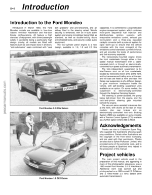 4
4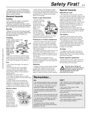 5
5 6
6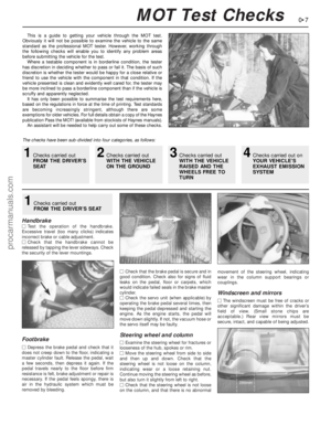 7
7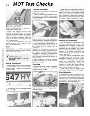 8
8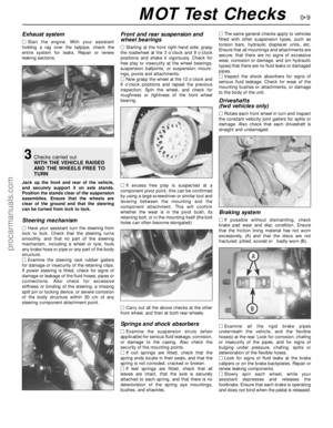 9
9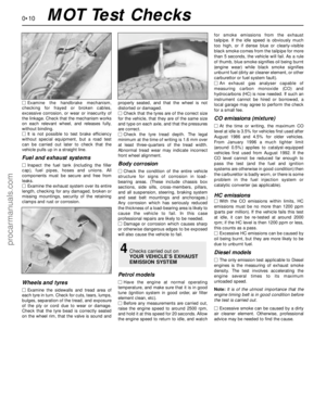 10
10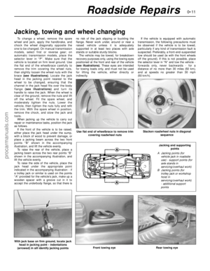 11
11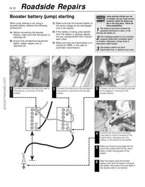 12
12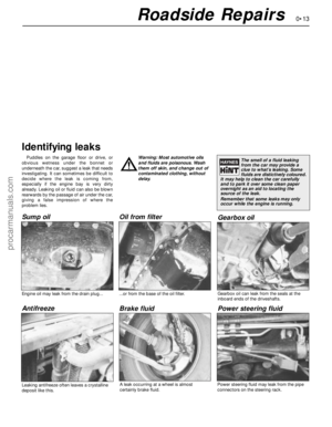 13
13 14
14 15
15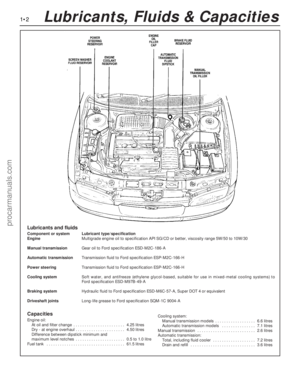 16
16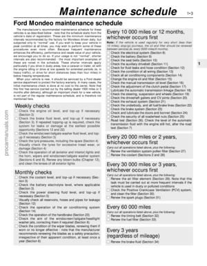 17
17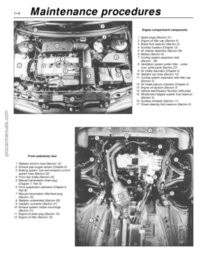 18
18 19
19 20
20 21
21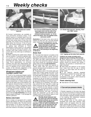 22
22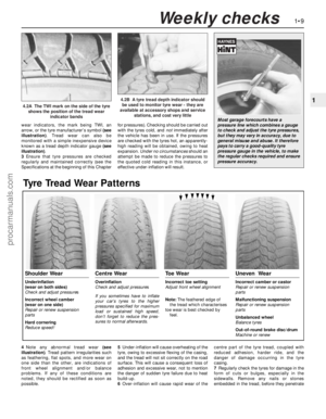 23
23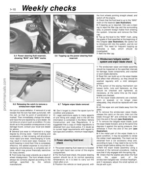 24
24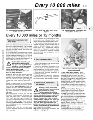 25
25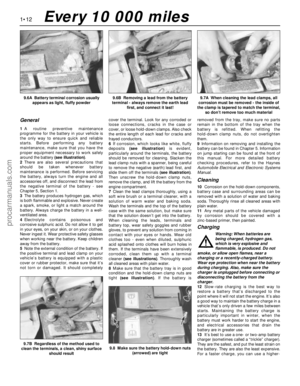 26
26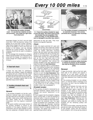 27
27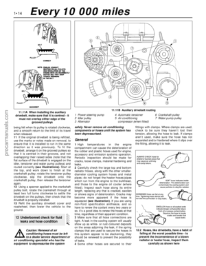 28
28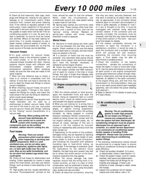 29
29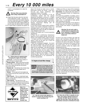 30
30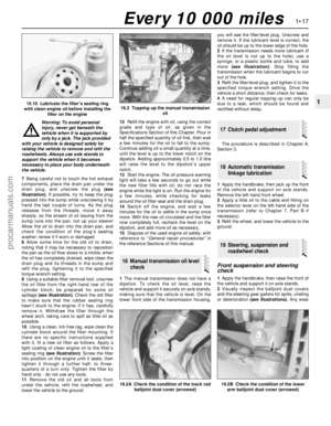 31
31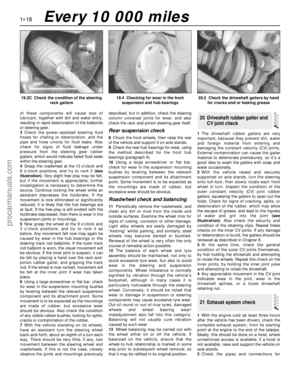 32
32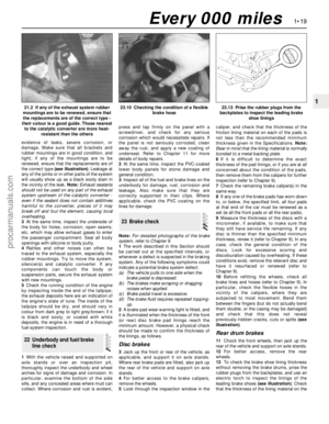 33
33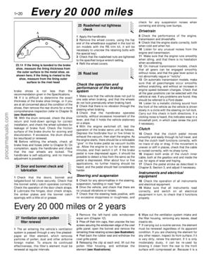 34
34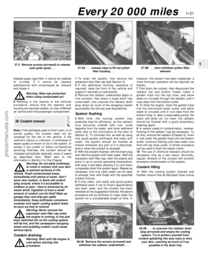 35
35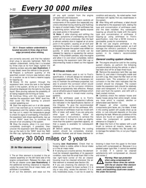 36
36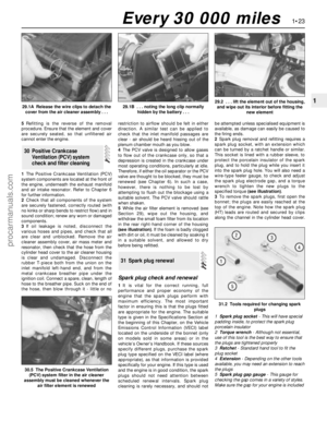 37
37 38
38 39
39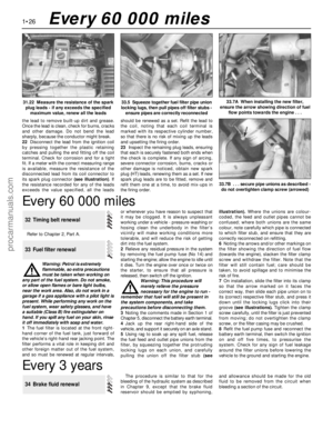 40
40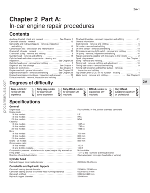 41
41 42
42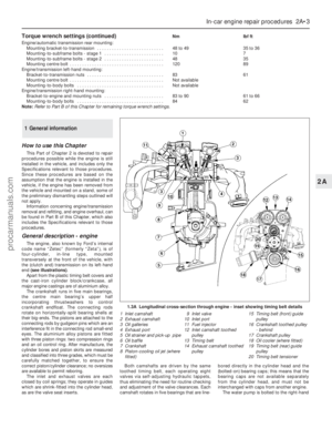 43
43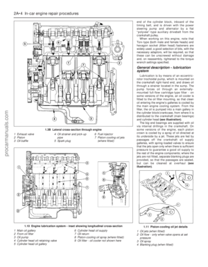 44
44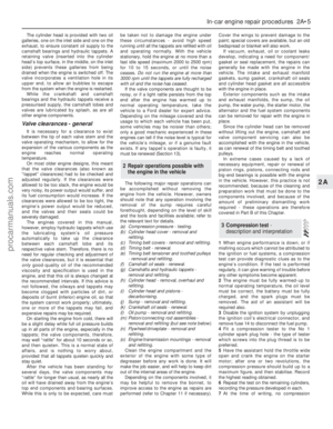 45
45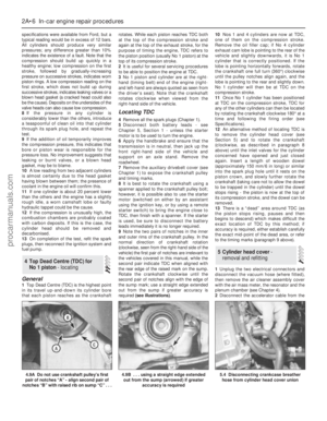 46
46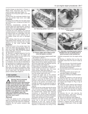 47
47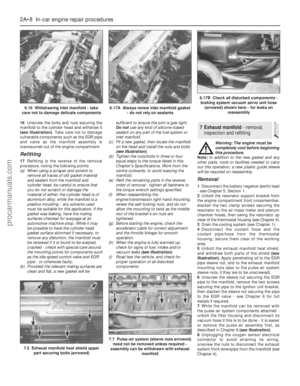 48
48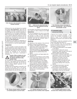 49
49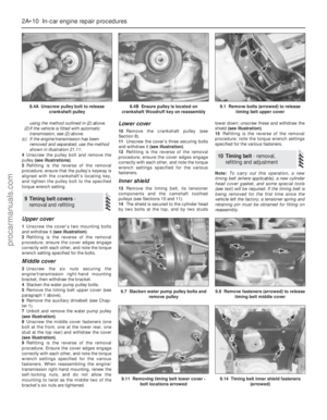 50
50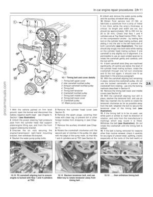 51
51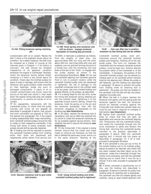 52
52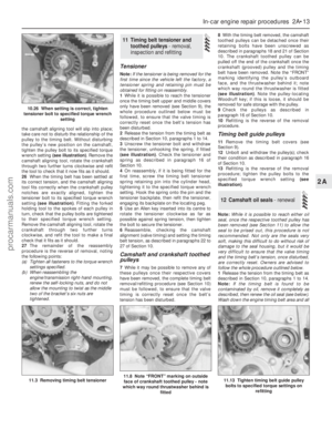 53
53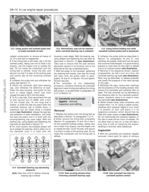 54
54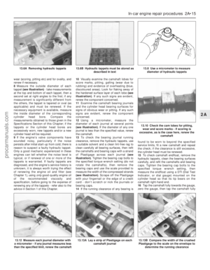 55
55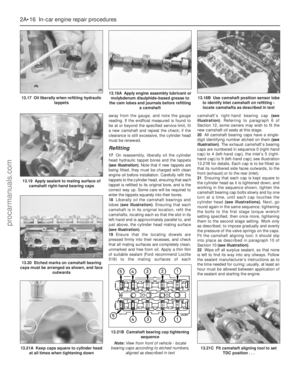 56
56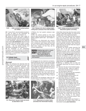 57
57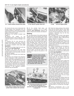 58
58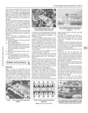 59
59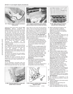 60
60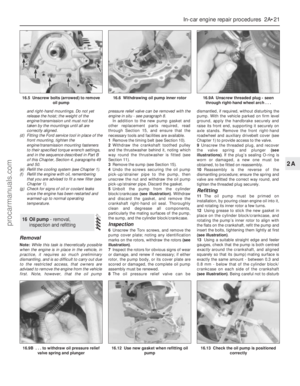 61
61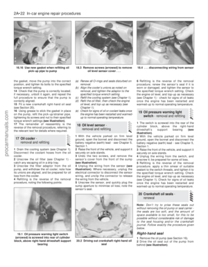 62
62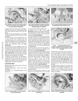 63
63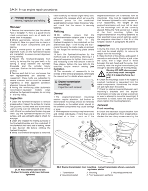 64
64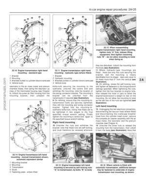 65
65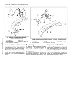 66
66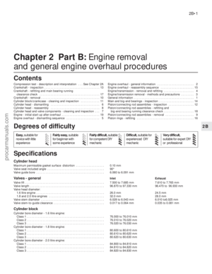 67
67 68
68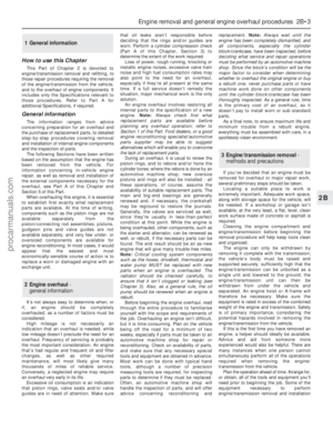 69
69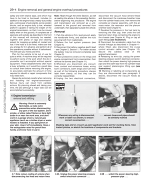 70
70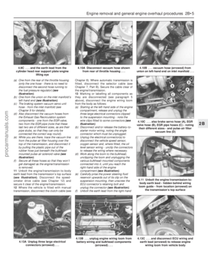 71
71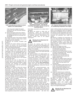 72
72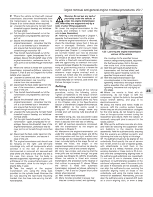 73
73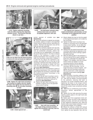 74
74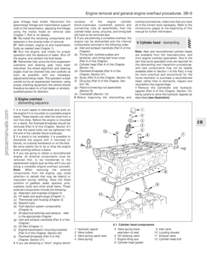 75
75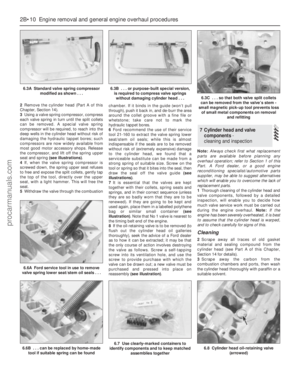 76
76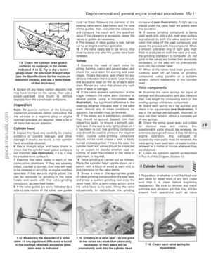 77
77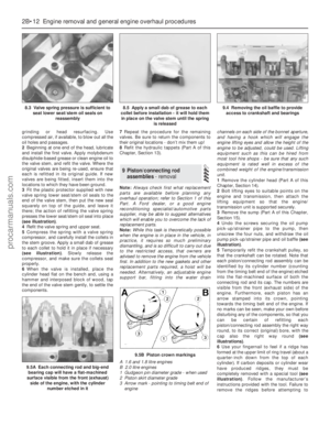 78
78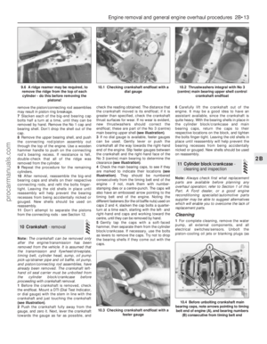 79
79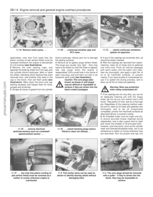 80
80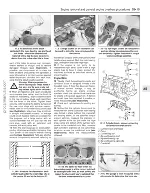 81
81 82
82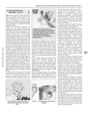 83
83 84
84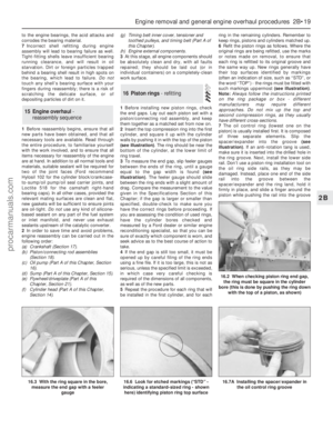 85
85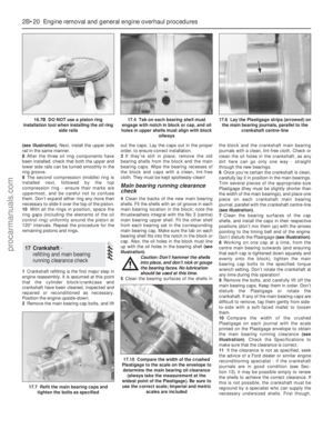 86
86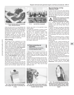 87
87 88
88 89
89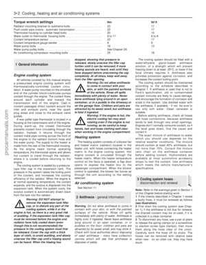 90
90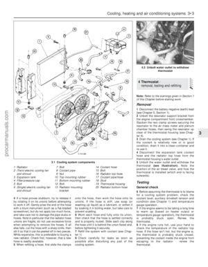 91
91 92
92 93
93 94
94 95
95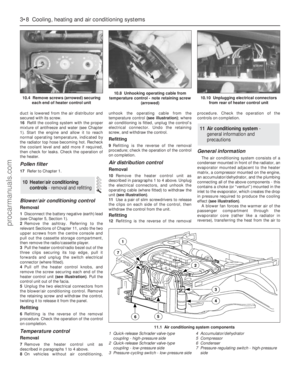 96
96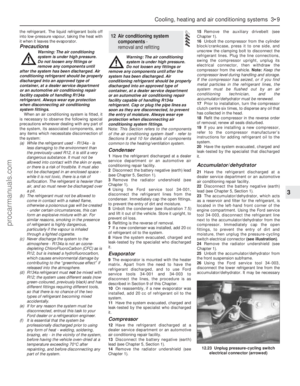 97
97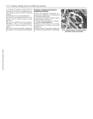 98
98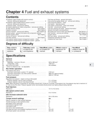 99
99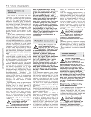 100
100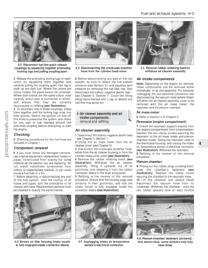 101
101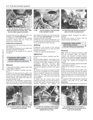 102
102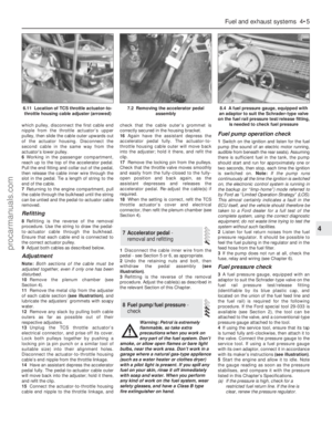 103
103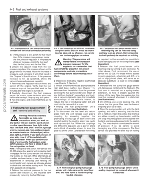 104
104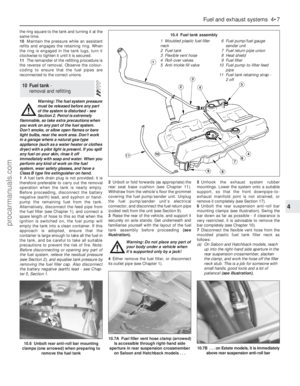 105
105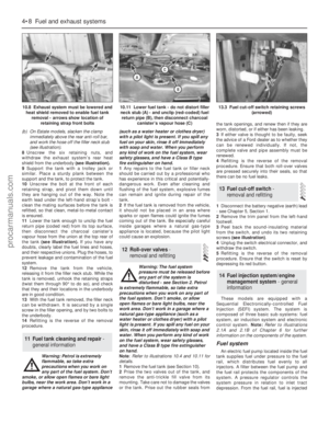 106
106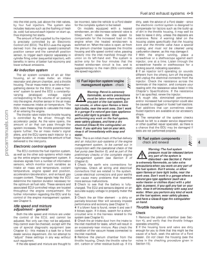 107
107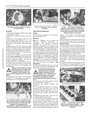 108
108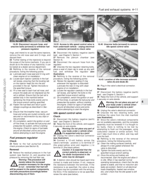 109
109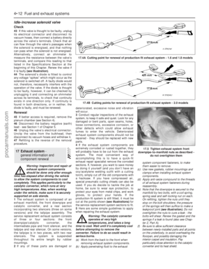 110
110 111
111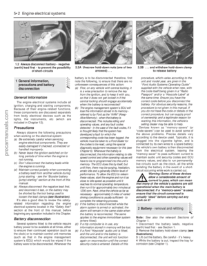 112
112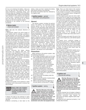 113
113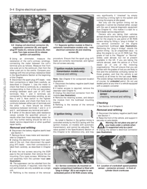 114
114 115
115 116
116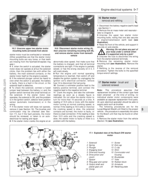 117
117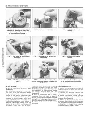 118
118 119
119 120
120 121
121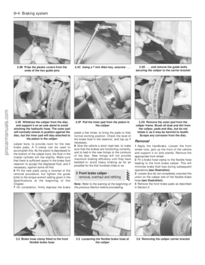 122
122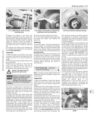 123
123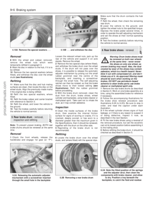 124
124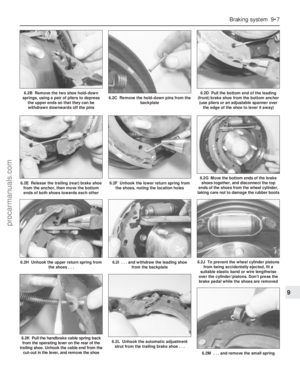 125
125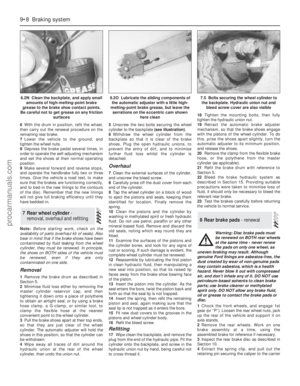 126
126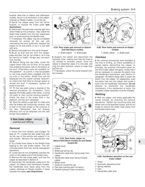 127
127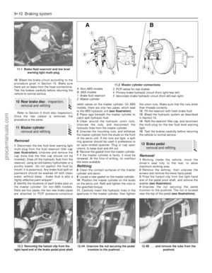 128
128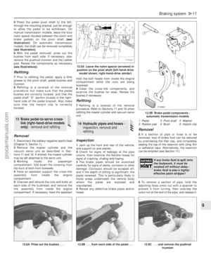 129
129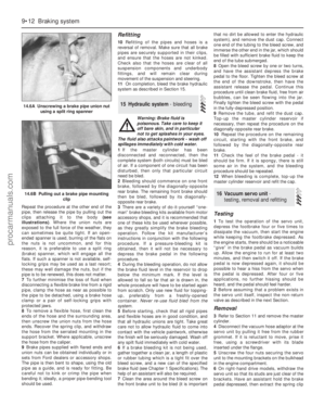 130
130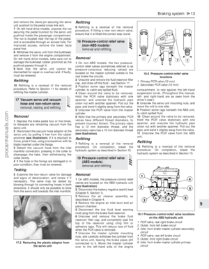 131
131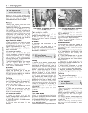 132
132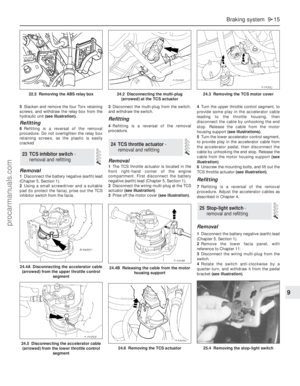 133
133 134
134 135
135 136
136 137
137 138
138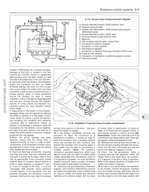 139
139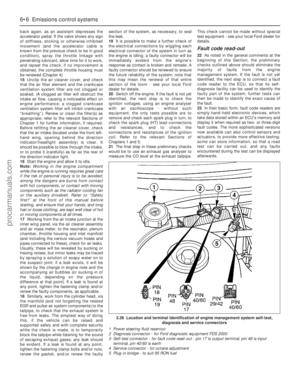 140
140 141
141 142
142 143
143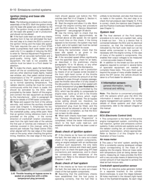 144
144 145
145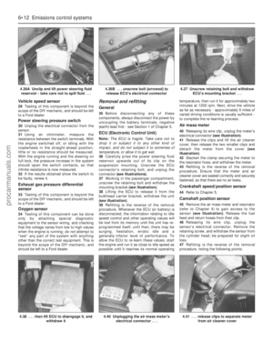 146
146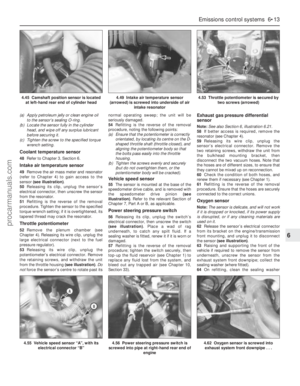 147
147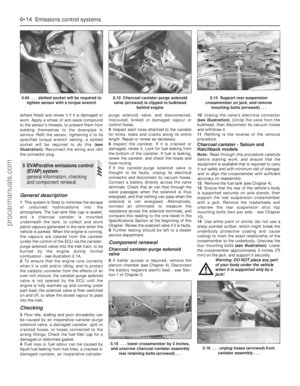 148
148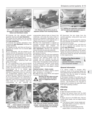 149
149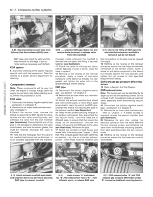 150
150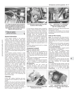 151
151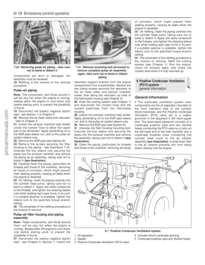 152
152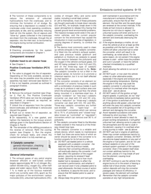 153
153 154
154 155
155 156
156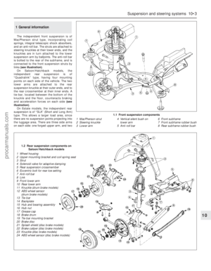 157
157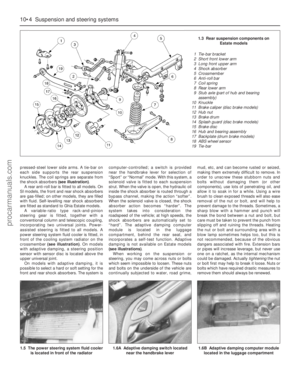 158
158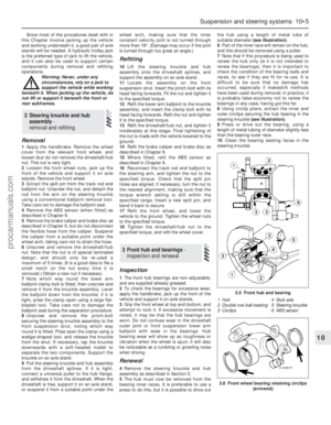 159
159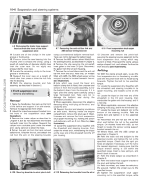 160
160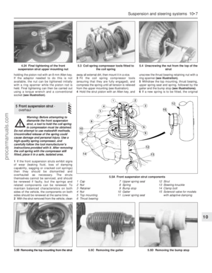 161
161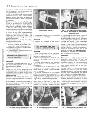 162
162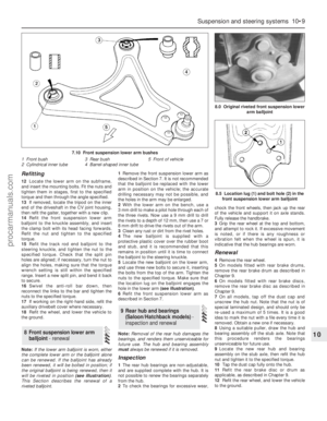 163
163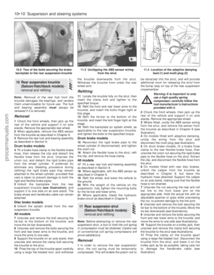 164
164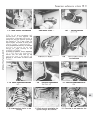 165
165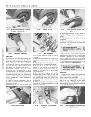 166
166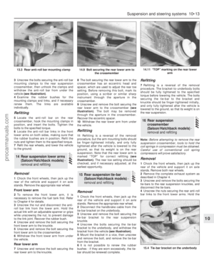 167
167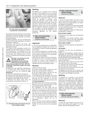 168
168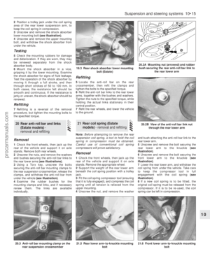 169
169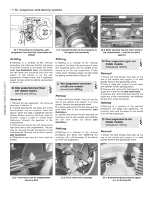 170
170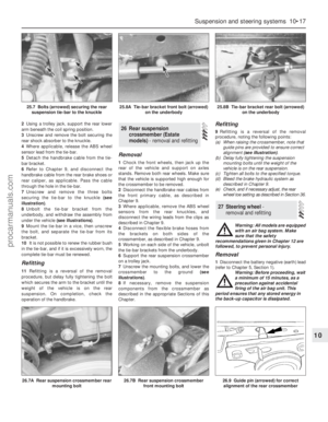 171
171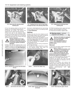 172
172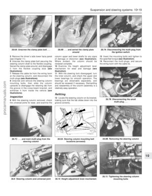 173
173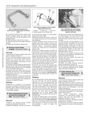 174
174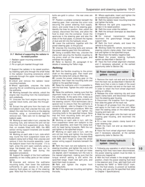 175
175 176
176 177
177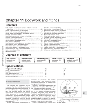 178
178 179
179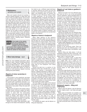 180
180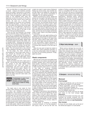 181
181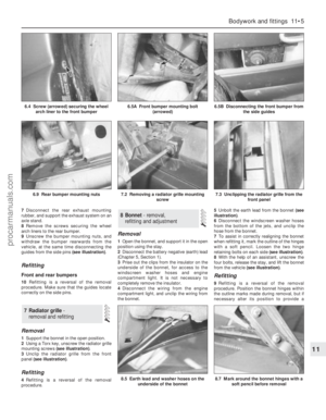 182
182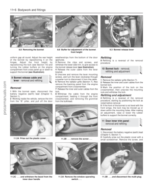 183
183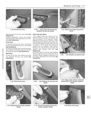 184
184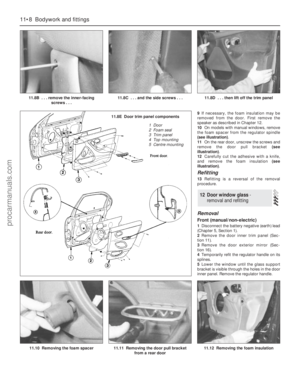 185
185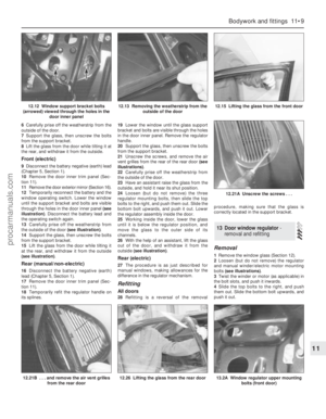 186
186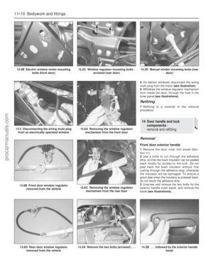 187
187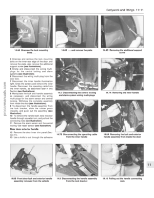 188
188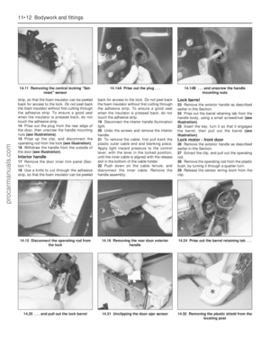 189
189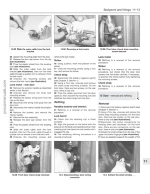 190
190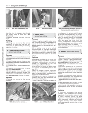 191
191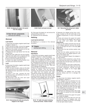 192
192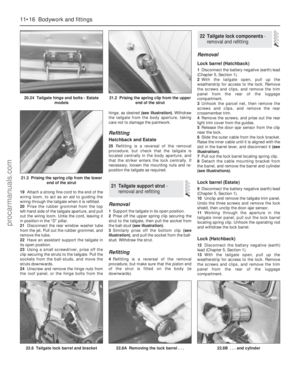 193
193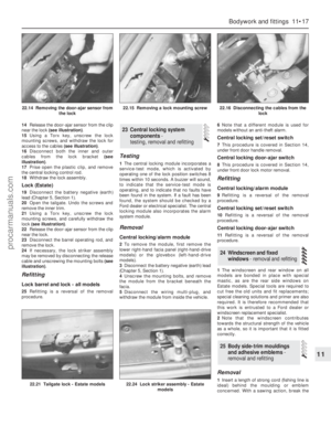 194
194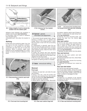 195
195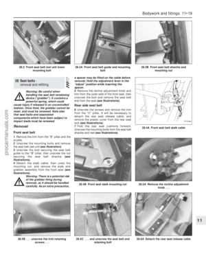 196
196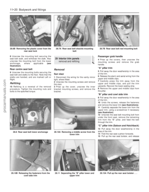 197
197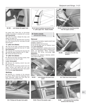 198
198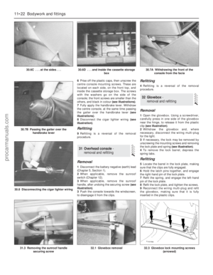 199
199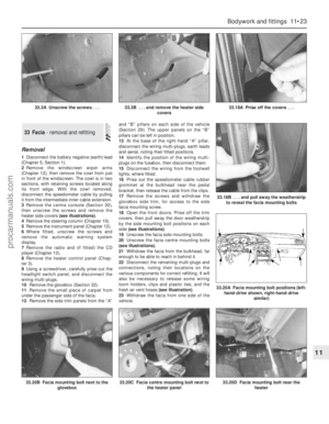 200
200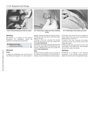 201
201 202
202 203
203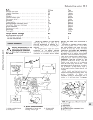 204
204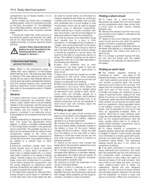 205
205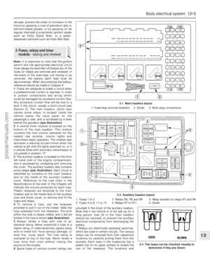 206
206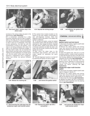 207
207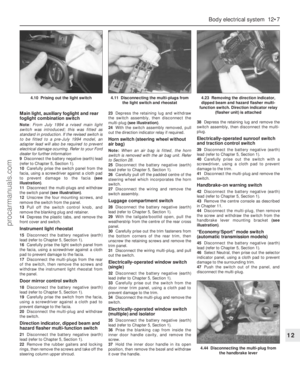 208
208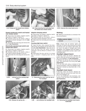 209
209 210
210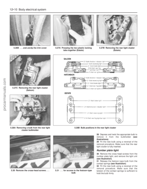 211
211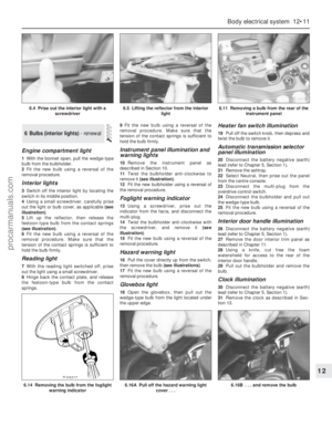 212
212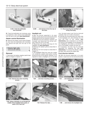 213
213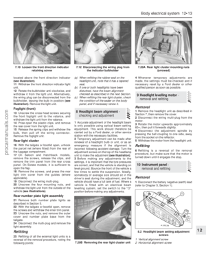 214
214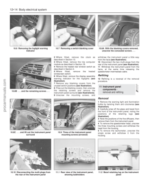 215
215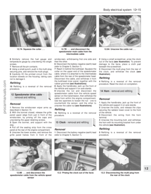 216
216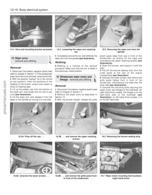 217
217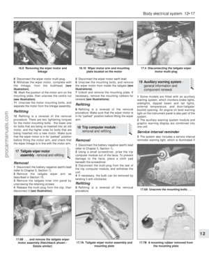 218
218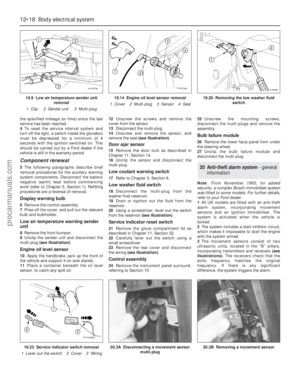 219
219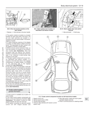 220
220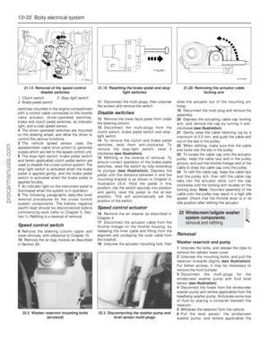 221
221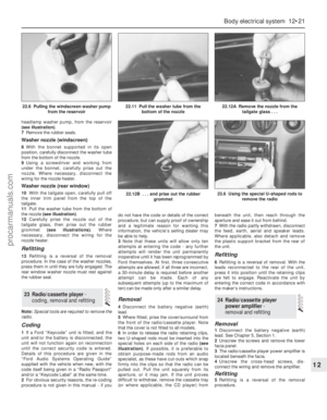 222
222 223
223 224
224 225
225 226
226 227
227 228
228 229
229 230
230 231
231 232
232 233
233 234
234 235
235 236
236 237
237 238
238 239
239 240
240 241
241 242
242 243
243 244
244 245
245 246
246 247
247 248
248 249
249 250
250 251
251 252
252 253
253 254
254 255
255 256
256 257
257 258
258 259
259 260
260 261
261 262
262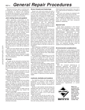 263
263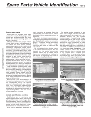 264
264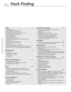 265
265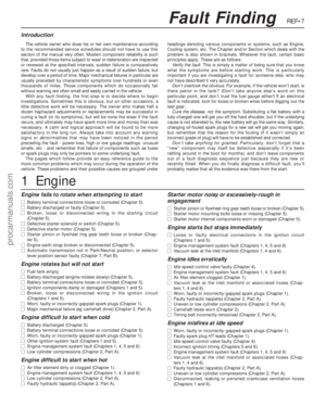 266
266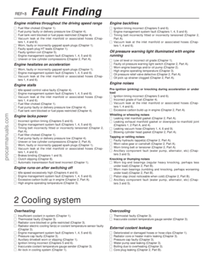 267
267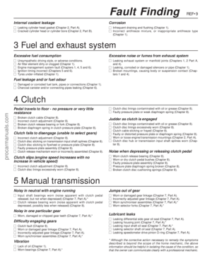 268
268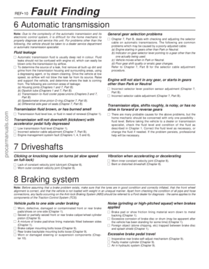 269
269 270
270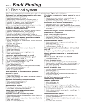 271
271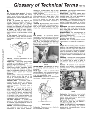 272
272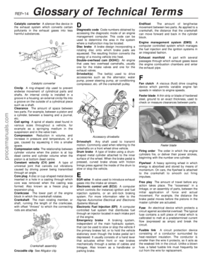 273
273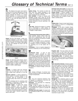 274
274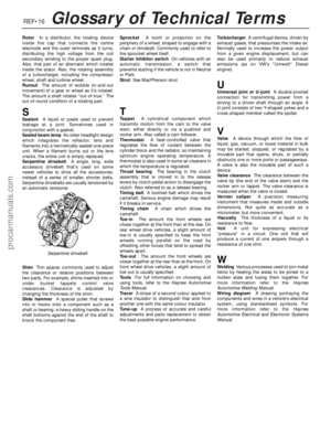 275
275 276
276 277
277 278
278