Page 129 of 279

5Press the pedal pivot shaft to the left,
through the mounting bracket, just far enough
to allow the pedal to be withdrawn. On
manual transmission models, leave the blue
nylon spacer (located between the clutch and
brake pedals) on the pivot shaft (see
illustration). On automatic transmission
models, the shaft can be removed completely
(see illustration).
6With the pedal removed, prise out the
bushes from each side. If necessary, also
remove the pushrod trunnion and the rubber
pad. Renew the components as necessary
(see illustrations).
Refitting
7Prior to refitting the pedal, apply a little
grease to the pivot shaft, pedal bushes and
trunnion.
8Refitting is a reversal of the removal
procedure, but make sure that the pedal
bushes are correctly located, and that the
pedal shaft “D” section locates in the right-
hand side of the pedal bracket. Also make
sure that the hairpin clip is correctly
located.
Removal
1Disconnect the battery negative (earth) lead
(Chapter 5, Section 1).
2Remove the master cylinder and the
vacuum servo unit as described in Sec-
tions 11 and 16. If wished, the master cylinder
may be left attached to the servo unit.
3Working inside the passenger
compartment, fold down the covering from
the front of both front footwells.
4Have an assistant support the cross-link
assembly from inside the engine
compartment.
5Unscrew and remove the nuts and bolts on
each side of the bulkhead, and remove the
link assembly from inside the engine
compartment. If necessary, have the assistanthold the bolt heads from inside the engine
compartment while the nuts are being
loosened.
6Clean the cross-link components, and
examine the bushes for wear. Renew the
bushes if necessary.
Refitting
7Refitting is a reversal of the removal
procedure. Refer to Sections 11 and 16 when
refitting the master cylinder and vacuum servo
unit.
Inspection
1Jack up the front and rear of the vehicle,
and support on axle stands.
2Check for signs of leakage at the pipe
unions, then examine the flexible hoses for
signs of cracking, chafing and fraying.
3The brake pipes should be examined
carefully for signs of dents, corrosion or other
damage. Corrosion should be scraped off,
and if the depth of pitting is significant, the
pipes renewed. This is particularly likely in
those areas underneath the vehicle body
where the pipes are exposed and
unprotected.
4Renew any defective brake pipes and/or
hoses.
Removal
5If a section of pipe or hose is to be
removed, loss of brake fluid can be reduced
by unscrewing the filler cap, and completely
sealing the top of the reservoir with cling film
or adhesive tape. Alternatively, the reservoir
can be emptied (see Section 11).
6To remove a section of pipe, hold the
adjoining hose union nut with a spanner to
prevent it from turning, then unscrew the
union nut at the end of the pipe, and release it.
14 Hydraulic pipes and hoses -
inspection, removal and
refitting
13 Brake pedal-to-servo cross-
link (right-hand-drive models
only)- removal and refitting
Braking system 9•11
9
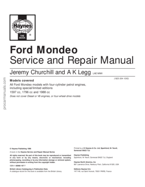
12.6A Prise out the bushes . . .12.6B . . . from each side of the pedal . . .12.6C . . . and remove the pushrod
trunnion
12.5A Leave the nylon spacer (arrowed) in
position on the pivot shaft (left-hand-drive
model shown, right-hand-drive similar)
12.5B Brake pedal components -
automatic transmission models
1 Pedal 3 Pivot shaft 5 Washer
2 Rubber pad 4 Bush 6 Hairpin clip
If any brake fluid is spilt onto
the bodywork, it must be
washed off without delay -
brake fluid is also a highly-
effective paint-stripper!
procarmanuals.com
Page 130 of 279
. Where the union nuts are
exposed to the full force of th")
Repeat the procedure at the other end of the
pipe, then release the pipe by pulling out the
clips attaching it to the body (see
illustrations). Where the union nuts are
exposed to the full force of the weather, they
can sometimes be quite tight. If an open-
ended spanner is used, burring of the flats on
the nuts is not uncommon, and for this
reason, it is preferable to use a split ring
(brake) spanner, which will engage all the
flats. If such a spanner is not available, self-
locking grips may be used as a last resort;
these may well damage the nuts, but if the
pipe is to be renewed, this does not matter.
7To further minimise the loss of fluid when
disconnecting a flexible brake line from a rigid
pipe, clamp the hose as near as possible to
the pipe to be detached, using a brake hose
clamp or a pair of self-locking grips with
protected jaws.
8To remove a flexible hose, first clean the
ends of the hose and the surrounding area,
then unscrew the union nuts from the hose
ends. Recover the spring clip, and withdraw
the hose from the serrated mounting in the
support bracket. Where applicable, unscrew
the hose from the caliper.
9Brake pipes supplied with flared ends and
union nuts can be obtained individually or in
sets from Ford dealers or accessory shops.
The pipe is then bent to shape, using the old
pipe as a guide, and is ready for fitting. Be
careful not to kink or crimp the pipe when
bending it; ideally, a proper pipe-bending tool
should be used.
Refitting
10Refitting of the pipes and hoses is a
reversal of removal. Make sure that all brake
pipes are securely supported in their clips,
and ensure that the hoses are not kinked.
Check also that the hoses are clear of all
suspension components and underbody
fittings, and will remain clear during
movement of the suspension and steering.
11On completion, bleed the brake hydraulic
system as described in Section 15.
Warning: Brake fluid is
poisonous. Take care to keep it
off bare skin, and in particular
not to get splashes in your eyes.
The fluid also attacks paintwork - wash off
spillages immediately with cold water.
1If the master cylinder has been
disconnected and reconnected, then the
complete system (both circuits) must be bled
of air. If a component of one circuit has been
disturbed, then only that particular circuit
need be bled.
2Bleeding should commence on one front
brake, followed by the diagonally-opposite
rear brake. The remaining front brake should
then be bled, followed by its diagonally-
opposite rear brake.
3There are a variety of do-it-yourself “one-
man” brake bleeding kits available from motor
accessory shops, and it is recommended that
one of these kits be used wherever possible,
as they greatly simplify the brake bleeding
operation. Follow the kit manufacturer’s
instructions in conjunction with the following
procedure. If a pressure-bleeding kit is
obtained, then it will not be necessary to
depress the brake pedal in the following
procedure.
4During the bleeding operation, do not allow
the brake fluid level in the reservoir to drop
below the minimum mark. If the level is
allowed to fall so far that air is drawn in, the
whole procedure will have to be started again
from scratch. Only use new fluid for topping-
up, preferably from a freshly-opened
container. Never re-use fluid bled from the
system.
5Before starting, check that all rigid pipes
and flexible hoses are in good condition, and
that all hydraulic unions are tight. Take great
care not to allow hydraulic fluid to come into
contact with the vehicle paintwork, otherwise
the finish will be seriously damaged. Wash off
any spilt fluid immediately with cold water.
6If a brake bleeding kit is not being used,
gather together a clean jar, a length of plastic
or rubber tubing which is a tight fit over the
bleed screw, and a new can of the specified
brake fluid (see Chapter 1 Specifications). The
help of an assistant will also be required.
7Clean the area around the bleed screw on
the front brake unit to be bled (it is importantthat no dirt be allowed to enter the hydraulic
system), and remove the dust cap. Connect
one end of the tubing to the bleed screw, and
immerse the other end in the jar, which should
be filled with sufficient brake fluid to keep the
end of the tube submerged.
8Open the bleed screw by one or two turns,
and have the assistant depress the brake
pedal to the floor. Tighten the bleed screw at
the end of the downstroke, then have the
assistant release the pedal. Continue this
procedure until clean brake fluid, free from air
bubbles, can be seen flowing into the jar.
Finally tighten the bleed screw with the pedal
in the fully-depressed position.
9Remove the tube, and refit the dust cap.
Top-up the master cylinder reservoir if
necessary, then repeat the procedure on the
diagonally-opposite rear brake.
10Repeat the procedure on the remaining
circuit, starting with the front brake, and
followed by the diagonally-opposite rear
brake.
11Check the feel of the brake pedal - it
should be firm. If it is spongy, there is still
some air in the system, and the bleeding
procedure should be repeated.
12When bleeding is complete, top-up the
master cylinder reservoir and refit the cap.
Testing
1To test the operation of the servo unit,
depress the footbrake four or five times to
dissipate the vacuum, then start the engine
while keeping the footbrake depressed. As
the engine starts, there should be a noticeable
“give” in the brake pedal as vacuum builds
up. Allow the engine to run for at least two
minutes, and then switch it off. If the brake
pedal is now depressed again, it should be
possible to hear a hiss from the servo when
the pedal is depressed. After four or five
applications, no further hissing should be
heard, and the pedal should feel harder.
2Before assuming that a problem exists in
the servo unit itself, inspect the non-return
valve as described in the next Section.
Removal
3Refer to Section 11 and remove the master
cylinder.
4Disconnect the vacuum hose adaptor at the
servo unit by pulling it free from the rubber
grommet. If it is reluctant to move, prise it
free, using a screwdriver with its blade
inserted under the flange.
5Unscrew the four nuts securing the servo
unit to the mounting brackets on the bulkhead
in the engine compartment.
6On right-hand drive models, withdraw the
servo unit so that its studs are just clear of the
brackets. Have an assistant hold the brake
pedal depressed, then extract the spring clip
16 Vacuum servo unit -
testing, removal and refitting
15 Hydraulic system - bleeding
9•12 Braking system
14.6A Unscrewing a brake pipe union nut
using a split ring spanner
14.6B Pulling out a brake pipe mounting
clip
procarmanuals.com
Page 131 of 279

and remove the clevis pin securing the servo
unit pushrod to the pedal cross-link arm.
7On left-hand drive models, unscrew the nut
securing the pedal trunnion to the servo unit
pushrod inside the passenger compartment.
The nut is located near the top of the pedal,
and is accessible through an access hole. For
improved access, remove the lower facia
panel first.
8Withdraw the servo unit from the bulkhead,
and remove it from the engine compartment.
On left-hand drive models, take care not to
damage the bulkhead rubber grommet as the
pushrod passes through it.
9Note that the servo unit cannot be
dismantled for repair or overhaul and, if faulty,
must be renewed.
Refitting
10Refitting is a reversal of the removal
procedure. Refer to Section 11 for details of
refitting the master cylinder.
Removal
1Depress the brake pedal four or five times,
to dissipate any remaining vacuum from the
servo unit.
2Disconnect the vacuum hose adaptor at the
servo unit, by pulling it free from the rubber
grommet (see illustration). If it is reluctant to
move, prise it free, using a screwdriver with its
blade inserted under the flange.
3Detach the vacuum hose from the inlet
manifold connection, pressing in the collar to
disengage the tabs, then withdrawing the
collar slowly.
4If the hose or the fixings are damaged or in
poor condition, they must be renewed.
Testing
5Examine the non-return valve for damage
and signs of deterioration, and renew it if
necessary. The valve may be tested by
blowing through its connecting hoses in both
directions. It should only be possible to blow
from the servo end towards the inlet manifold.
Refitting
6Refitting is a reversal of the removal
procedure. If fitting a new non-return valve,
ensure that it is fitted the correct way round.
Removal
1On non-ABS models, the two pressure-
control relief valves (sometimes referred to as
pressure-conscious reducing valves) are
located on the master cylinder outlets to the
rear brake line circuits.
2Unscrew and remove the fluid reservoir filler
cap, and draw off the fluid - see Section 11.
3Position some rags beneath the master
cylinder, to catch any spilled fluid.
4Clean around the valve to be removed.
Hold the PCR valve stationary with one
spanner, and unscrew the hydraulic pipe
union nut with another spanner. Pull out the
pipe, and bend it slightly away from the valve.
5Unscrew the PCR valve from the master
cylinder.
6Note that the primary and secondary PCR
valves have different thread diameters, to
prevent incorrect fitment. The primary valve
has a 12 mm diameter thread, and the
secondary valve has a 10 mm diameter thread
(see illustration).
Refitting
7Refitting is a reversal of the removal
procedure. On completion, bleed the
hydraulic system as described in Section 15.
Removal
1On ABS models, the pressure-control relief
valves are located on the ABS hydraulic unit
(see illustration).
2Disconnect the battery negative (earth) lead
(Chapter 5, Section 1).
3Remove the air cleaner assembly as
described in Chapter 4.
4Remove the engine air inlet duct and air
plenum chamber.
5Disconnect the low fluid level warning
multi-plug from the brake fluid reservoir.
6Unscrew and remove the brake fluid
reservoir filler cap, and completely seal the
top of the reservoir using cling film or
adhesive tape. This will reduce loss of fluid
when the PCR valve is removed.
7Unscrew the master cylinder mounting
nuts, and carefully withdraw the cylinder from
the servo unit, leaving the brake pipes still
connected to it. Move the master cylinder
over to the left-hand side of the enginecompartment, to rest against the left-hand
suspension turret. (Throughout this manual,
left- and right-hand are as seen from the
driver’s seat.)
8Unscrew the servo unit mounting nuts, and
move the unit to one side.
9Position some rags beneath the ABS unit,
to catch spilled fluid.
10Clean around the valve to be removed.
Hold the PCR valve stationary with one
spanner, and unscrew the hydraulic pipe
union nut with another spanner. Pull out the
pipe, and bend it slightly away from the valve.
11Unscrew the PCR valve from the ABS
unit.
Refitting
12Refitting is a reversal of the removal
procedure. On completion, bleed the
hydraulic system as described in Section 15.
19 Pressure-control relief valve
(ABS models) -
removal and refitting
18 Pressure-control relief valve
(non-ABS models) -
removal and refitting
17 Vacuum servo unit vacuum
hose and non-return valve -
removal, testing and refitting
Braking system 9•13
9
17.2 Removing the plastic adaptor from
the servo unit
18.6 Pressure-control relief valve
locations
1 Primary PCR valve (12 mm)
2 Secondary PCR valve (10 mm)
19.1 Pressure-control relief valve locations
on the ABS hydraulic unit
1 PCR valve, rear right brake circuit
2 Outlet, front left brake circuit
3 Inlet, from brake master cylinder secondary
circuit
4 PCR valve, rear left brake circuit
5 Outlet, front right brake circuit
6 Inlet, from brake master cylinder primary
circuit
procarmanuals.com
Page 132 of 279
,
individual spare parts are not available.
Removal
1Remove both pressu")
Note:If any part of the ABS hydraulic unit is
defective, it must be renewed as an assembly.
Apart from the relay box (Section 22),
individual spare parts are not available.
Removal
1Remove both pressure-control relief valves
as described in Section 19.
2Identify the location of the remaining brake
hydraulic pipes on the ABS hydraulic unit,
then unscrew the union nuts and pull out the
pipes. Carefully bend the pipes away from the
hydraulic unit, to allow the unit to be removed.
3Disconnect the multi-plugs from the
hydraulic unit. To disconnect the main 22-pin
multi-plug, push the locktab, then swivel the
multi-plug outwards and unhook it.
Right-hand drive models
4Have an assistant hold the brake pedal
depressed, then extract the spring clip and
remove the clevis pin securing the servo unit
pushrod to the pedal cross-link arm.
5Remove the vacuum servo unit from the
engine compartment.
Left-hand drive models
6Unscrew the nut securing the pedal
trunnion to the servo unit pushrod inside the
passenger compartment. The nut is located
near the top of the pedal, and is accessible
through an access hole. For improved access,
remove the lower facia panel first.
7Remove the vacuum servo unit, together
with the pushrod, from the engine
compartment. Take care not to damage the
rubber grommet in the bulkhead.
All models
8Unscrew the pump mounting nut.
9Raise the left-hand side of the ABS
hydraulic unit, then swivel the unit out of the
right-hand mounting. Take care not to lose the
bracket studs and insulator ring.
Refitting
10Locate the insulator ring on the pump
end, and fit the stud cap to the insulator ring.
11Lower the ABS hydraulic unit into
position, right-hand end first.
12Fit the right-hand bracket studs onto the
insulators.
13Lower the left-hand end of the ABS
hydraulic unit onto the bracket, then fit and
tighten the pump mounting nut.
Left-hand drive models
14Locate the vacuum servo unit and
pushrod on the bulkhead bracket, taking care
not to damage the rubber grommet.
15Insert the pushrod in the pedal trunnion,
and tighten the nut.
16Refit the lower facia panel if it was
removed.
Right-hand drive models
17Locate the vacuum servo unit and
pushrod on the bulkhead bracket.
18Refit the clevis pin and spring clip
securing the servo unit pushrod to the pedal
cross-link arm.
All models
19Reconnect the multi-plugs to the
hydraulic unit.
20Reconnect the brake pipes to the
hydraulic unit, and tighten the union nuts.
21Refit both pressure-control relief valves,
with reference to Section 20.
Testing
1Checking of the sensors is done before
removal, connecting a voltmeter to the
disconnected sensor multi-plug. Using an
analogue (moving coil) meter is not practical,
since the meter does not respond quickly
enough. A digital meter having an AC facility
may be used to check that the sensor is
operating correctly. To do this, raise the
relevant wheel then disconnect the wiring to
the ABS sensor and connect the meter to it.
Spin the wheel and check that the output
voltage is between 1.5 and 2.0 volts,
depending on how fast the wheel is spun.
Alternatively, an oscilloscope may be used to
check the output of the sensor - an alternating
current will be traced on the screen, of
magnitude depending on the speed of the
rotating wheel.
2If the sensor output is low or zero, renew
the sensor.
Removal
Front wheel sensor
3Apply the handbrake, jack up the front of
the vehicle and support it on axle stands.
Remove the relevant wheel.
4Unscrew the sensor mounting bolt located
on the steering knuckle, and withdraw the
sensor (see illustrations).
5Remove the sensor wiring loom from thesupport brackets on the front suspension
strut and wheel arch.
6Prise out the stud clips, and remove the
Torx screws and screw clips holding the wheel
arch liner in position. Withdraw the liner.
7Disconnect the multi-plug, and withdraw
the sensor and wiring loom.
Rear wheel sensor
8Chock the front wheels, and engage 1st
gear (or “P”). Jack up the rear of the vehicle
and support it on axle stands. Remove the
relevant wheel.
9Unscrew the sensor mounting bolt, located
on the brake backplate (drum brakes) or rear
suspension knuckle (disc brakes), and
withdraw the sensor.
10On disc brake models, prise out the stud
clips, and remove the Torx screws and screw
clips holding the wheel arch liner in position.
Withdraw the liner.
11Disconnect the sensor wiring loom from
the supports on the rear suspension strut (or
knuckle) and wheel arch.
12Working inside the vehicle, lift the rear
seat cushion, then disconnect the multi-plug
for the sensor wiring loom (see illustration).
13Withdraw the sensor and wiring loom
through the rubber grommet in the rear floor.
Refitting
Front and rear wheel sensors
14Refitting is a reversal of the removal
procedure.
Removal
1Disconnect the battery negative (earth) lead
(Chapter 5, Section 1).
2Detach the vacuum hose from the inlet
manifold connection, pressing in the collar to
disengage the tabs, then withdrawing the
collar slowly.
3To improve access, free the heater hose
from its retaining clips, and position it clear of
the relay box.
4Disconect the wiring connector(s) from the
relay box and, where necessary, the speed
sender unit.
22 ABS relay box -
removal and refitting
21 ABS wheel sensor -
testing, removal and refitting
20 ABS hydraulic unit -
removal and refitting
9•14 Braking system
21.4 Unscrew the mounting bolt and
remove the ABS sensor21.12 Rear ABS sensor wiring multi-plug
located beneath the rear seat
procarmanuals.com
Page 133 of 279
.
Refitting
6Refitting is a reversal of the removal
procedure. Do not overtight")
5Slacken and remove the four Torx retaining
screws, and withdraw the relay box from the
hydraulic unit (see illustration).
Refitting
6Refitting is a reversal of the removal
procedure. Do not overtighten the relay box
retaining screws, as the plastic is easily
cracked
Removal
1Disconnect the battery negative (earth) lead
(Chapter 5, Section 1).
2Using a small screwdriver and a suitable
pad (to protect the facia), prise out the TCS
inhibitor switch from the facia.3Disconnect the multi-plug from the switch,
and withdraw the switch.
Refitting
4Refitting is a reversal of the removal
procedure.
Removal
1The TCS throttle actuator is located in the
front right-hand corner of the engine
compartment. First disconnect the battery
negative (earth) lead (Chapter 5, Section 1).
2Disconnect the wiring multi-plug at the TCS
actuator (see illustration).
3Prise off the motor cover (see illustration).4Turn the upper throttle control segment, to
provide some play in the accelerator cable
leading to the throttle housing, then
disconnect the cable by unhooking the end
stop. Release the cable from the motor
housing support (see illustrations).
5Turn the lower accelerator control segment,
to provide play in the accelerator cable from
the accelerator pedal, then disconnect the
cable by unhooking the end stop. Release the
cable from the motor housing support (see
illustration).
6Unscrew the mounting bolts, and lift out the
TCS throttle actuator (see illustration).
Refitting
7Refitting is a reversal of the removal
procedure. Adjust the accelerator cables as
described in Chapter 4.
Removal
1Disconnect the battery negative (earth) lead
(Chapter 5, Section 1).
2Remove the lower facia panel, with
reference to Chapter 11.
3Disconnect the wiring multi-plug from the
switch.
4Rotate the switch anti-clockwise by a
quarter-turn, and withdraw it from the pedal
bracket (see illustration).
25 Stop-light switch -
removal and refitting
24 TCS throttle actuator -
removal and refitting
23 TCS inhibitor switch -
removal and refitting
Braking system 9•15
9
24.4B Releasing the cable from the motor
housing support24.4A Disconnecting the accelerator cable
(arrowed) from the upper throttle control
segment
24.5 Disconnecting the accelerator cable
(arrowed) from the lower throttle control
segment24.6 Removing the TCS actuator
22.5 Removing the ABS relay box24.2 Disconnecting the multi-plug
(arrowed) at the TCS actuator24.3 Removing the TCS motor cover
25.4 Removing the stop-light switch
procarmanuals.com
Page 134 of 279

Refitting and adjustment
5With the switch removed, reset it by fully
extending its plunger.
6Depress the brake pedal until the distance
between the pedal and mounting bracket is as
shown (see illustration).
7Hold the pedal in this position, and refit the
stop-light switch to the mounting bracket .
8With the switch securely clipped in position,
release the brake pedal, and gently pull it fully
back to the at-rest position. This will
automatically set the adjustment of the stop-
light switch.
9reconnect the wiring connector and the
battery, and check the operation of the switch
prior to refitting the lower facia panel (Chapter 11).
Removal
1Raise the front and rear of the vehicle, and
support it on axle stands. Fully release the
handbrake lever.
2Remove the centre console as described in
Chapter 11.
3Working beneath the vehicle, release the
exhaust system from the rubber mountings.
Lower the exhaust system as far as possible,
supporting it on blocks or more axle stands.
4Detach the exhaust heat shield from the
underbody.
5Unhook the secondary (rear) handbrake
cables from the equaliser bar.
6Working inside the vehicle, unscrew and
remove the two mounting bolts securing the
handbrake lever to the floor (see illustration).7Turn the handbrake lever upsidedown, then
disconnect the primary cable end from the
segment.
8Withdraw the handbrake from inside the
vehicle.
Refitting
9Refitting is a reversal of the removal
procedure, making sure that the primary cable
is correctly located in the segment. Check the
operation of the handbrake before returning
the vehicle to normal service.
Removal
Primary (front)
1Remove the handbrake lever as described
in Section 26.
2Prise the grommet from the underbody,
and withdraw the cable from beneath the
vehicle.
Secondary (rear)
3Chock the front wheels, and engage 1st
gear (or “P”). Jack up the rear of the vehicle
and support it on axle stands. Fully release
the handbrake lever.
4Remove the relevant rear wheel.5Working beneath the vehicle, release the
exhaust system from the rubber mountings.
Lower the exhaust system as far as possible,
supporting it on blocks or more axle stands.
6Unbolt the exhaust heat shield from the
underbody.
7Unhook the relevant cable from the
equaliser bar.
8On drum brake models, remove the rear
brake shoes on the relevant side as described
in Section 6, then remove the outer cable from
the backplate by compressing the three
retaining lugs (use a suitable ring spanner)
and pushing the cable through (see
illustration).
9On disc brake models, unhook the end of
the cable from the handbrake operating arm
on the rear caliper.
10Release the lugs securing the outer cable
to the underbody brackets, then release the
cable from the clips, and withdraw it from
under the vehicle (see illustrations).
Refitting
All cables
11Refitting is a reversal of the removal
procedure, but make sure that the cable end
fittings are correctly located. Check the
operation of the handbrake before returning
the vehicle to normal service.
27 Handbrake cables -
removal and refitting
26 Handbrake lever -
removal and refitting
9•16 Braking system
25.6 To ensure correct adjustment,
position the brake pedal as shown prior to
refitting the switch to its mounting bracket
26.6 Handbrake lever mounting bolts27.8 Using a ring spanner to compress the
retaining lugs securing the outer cable to
the backplate
27.10A Release the lugs using a ring
spanner . . .27.10B . . . and remove the outer cable
from the underbody brackets
procarmanuals.com
Page 135 of 279

Chapter 6 Emissions control systems
Catalytic converter - general information, checking
and component renewal . . . . . . . . . . . . . . . . . . . . . . . . . . . . . . . . 9
Diagnosis system - general information . . . . . . . . . . . . . . . . . . . . . . 3
Electronic control system - description and precautions . . . . . . . . . 2
Engine compartment wiring check . . . . . . . . . . . . . . . See Chapter 1
EVAPorative emissions control (EVAP) system - general
information, checking and component renewal . . . . . . . . . . . . . . 5
Exhaust Gas Recirculation (EGR) system - general
information, checking and component renewal . . . . . . . . . . . . . . 6
Exhaust system check . . . . . . . . . . . . . . . . . . . . . . . . . See Chapter 1General information . . . . . . . . . . . . . . . . . . . . . . . . . . . . . . . . . . . . . . 1
Information sensors - general information, testing,
removal and refitting . . . . . . . . . . . . . . . . . . . . . . . . . . . . . . . . . . . 4
Positive Crankcase Ventilation (PCV) system - general
information, checking and component renewal . . . . . . . . . . . . . . 8
Positive Crankcase Ventilation (PCV) system check
and filter cleaning . . . . . . . . . . . . . . . . . . . . . . . . . . . . . See Chapter 1
Pulse-air system - general information, checking
and component renewal . . . . . . . . . . . . . . . . . . . . . . . . . . . . . . . . 7
Underbonnet hose check . . . . . . . . . . . . . . . . . . . . . . . See Chapter 1
Crankshaft speed/position sensor
Resistance . . . . . . . . . . . . . . . . . . . . . . . . . . . . . . . . . . . . . . . . . . . . . . . . 200 to 450 ohms
Camshaft position sensor
Resistance . . . . . . . . . . . . . . . . . . . . . . . . . . . . . . . . . . . . . . . . . . . . . . . . 200 to 900 ohms
Intake air temperature sensor
Resistance:
At -40°C . . . . . . . . . . . . . . . . . . . . . . . . . . . . . . . . . . . . . . . . . . . . . . . . 860 to 900 k ohms
At 20°C . . . . . . . . . . . . . . . . . . . . . . . . . . . . . . . . . . . . . . . . . . . . . . . . 35 to 40 k ohms
At 100°C . . . . . . . . . . . . . . . . . . . . . . . . . . . . . . . . . . . . . . . . . . . . . . . 1.9 to 2.5 k ohms
At 120°C . . . . . . . . . . . . . . . . . . . . . . . . . . . . . . . . . . . . . . . . . . . . . . . 1.0 to 1.3 k ohms
Throttle potentiometer
Resistance - see text . . . . . . . . . . . . . . . . . . . . . . . . . . . . . . . . . . . . . . . 400 to 6000 ohms
Power steering pressure switch
Operating pressure - green switch body:
Contacts open - infinite resistance . . . . . . . . . . . . . . . . . . . . . . . . . . 31.5 ± 3.5 bars
Contacts close - 0 to 2.5 ohms resistance . . . . . . . . . . . . . . . . . . . . Between 13.5 and 24.0 bars
Charcoal canister-purge solenoid valve
Resistance . . . . . . . . . . . . . . . . . . . . . . . . . . . . . . . . . . . . . . . . . . . . . . . . 50 to 120 ohms
Pulse-air solenoid valve
Resistance . . . . . . . . . . . . . . . . . . . . . . . . . . . . . . . . . . . . . . . . . . . . . . . . 50 to 120 ohms
Torque wrench settingsNm lbf ft
Camshaft position sensor screw . . . . . . . . . . . . . . . . . . . . . . . . . . . . . . . 18 to 23 13 to 17
Intake air temperature sensor . . . . . . . . . . . . . . . . . . . . . . . . . . . . . . . . . 23 17
Oxygen sensor . . . . . . . . . . . . . . . . . . . . . . . . . . . . . . . . . . . . . . . . . . . . 60 44
Exhaust Gas Recirculation (EGR) system components:
Valve-to-inlet manifold bolts . . . . . . . . . . . . . . . . . . . . . . . . . . . . . . . . 9 6
Pipe-to-ignition coil screws . . . . . . . . . . . . . . . . . . . . . . . . . . . . . . . . . 10 7
Pulse-air system components:
Filter housing mounting bolt . . . . . . . . . . . . . . . . . . . . . . . . . . . . . . . . 47 35
Piping-to-exhaust manifold sleeve nuts . . . . . . . . . . . . . . . . . . . . . . . 32 24
6•1
Easy,suitable for
novice with little
experienceFairly easy,suitable
for beginner with
some experienceFairly difficult,suitable
for competent DIY
mechanicDifficult,suitable for
experienced DIY
mechanicVery difficult,
suitable for expert DIY
or professional
Degrees of difficulty
Specifications Contents
6
procarmanuals.com
Page 136 of 279

To minimise pollution of the atmosphere
from incompletely-burned and evaporating
gases, and to maintain good driveability and
fuel economy, a number of emission control
systems are used on these vehicles. They
include the following:
(a) The engine management system
(comprising both fuel and ignition sub-
systems) itself.
(b) Positive Crankcase Ventilation (PCV)
system.
(c) Evaporative Emissions Control (EVAP)
system.
(d) Exhaust Gas Recirculation (EGR) system.
(e) Catalytic converter.
The Sections of this Chapter include
general descriptions, checking procedures
within the scope of the home mechanic, and
component renewal procedures (when
possible) for each of the systems listed above.
Before assuming an emissions control system
is malfunctioning, check the fuel and ignition
systems carefully (see Chapters 4 and 5). The
diagnosis of some emission control devices
requires specialised tools, equipment and
training. If checking and servicing become too
difficult, or if a procedure is beyond the scope ofyour skills, consult your dealer service
department or other specialist.
This doesn’t mean, however, that emission
control systems are particularly difficult to
maintain and repair. You can quickly and
easily perform many checks, and do most of
the regular maintenance, at home with
common tune-up and hand tools. Note:The
most frequent cause of emissions problems is
simply a loose or broken electrical connector
or vacuum hose, so always check the
electrical connectors and vacuum hoses first.
Pay close attention to any special
precautions outlined in this Chapter. It should
be noted that the illustrations of the various
systems may not exactly match the system
installed on your vehicle, due to changes
made by the manufacturer during production
or from year-to-year.
Vehicles sold in some areas will carry a
Vehicle Emissions Control Information (VECI)
label, and a vacuum hose diagram located in
the engine compartment. These contain
important specifications and setting
procedures for the various emissions control
systems, with the vacuum hose diagram
identifying emissions control components.
When servicing the engine or emissions
systems, the VECI label in your particular
vehicle should always be checked for up-to-
date information.Description
The EEC-IV (Ford’s fourth-generation
Electronic Engine Control system) engine
management system controls fuel injection by
means of a microcomputer known as the ECU
(Electronic Control Unit) (see illustrations).
The ECU receives signals from various
sensors, which monitor changing engine
operating conditions such as intake air mass
(ie, intake air volume and temperature),
coolant temperature, engine speed,
acceleration/deceleration, exhaust oxygen
content, etc. These signals are used by the
ECU to determine the correct injection
duration.
The system is analogous to the central
nervous system in the human body - the
sensors (nerve endings) constantly relay
signals to the ECU (brain), which processes
the data and, if necessary, sends out a
command to change the operating
parameters of the engine (body) by means of
the actuators (muscles).
Here’s a specific example of how one
portion of this system operates. An oxygen
sensor, located in the exhaust downpipe,
2 Electronic control system -
description and precautions1 General information
6•2 Emissions control systems
procarmanuals.com
 1
1 2
2 3
3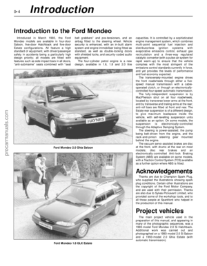 4
4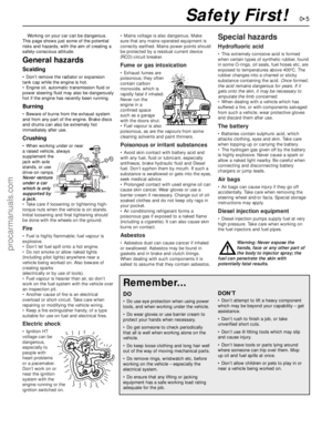 5
5 6
6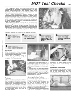 7
7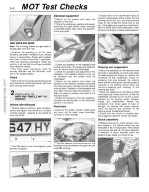 8
8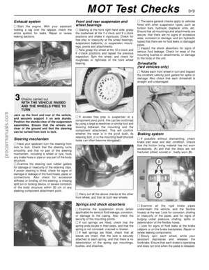 9
9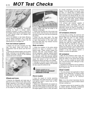 10
10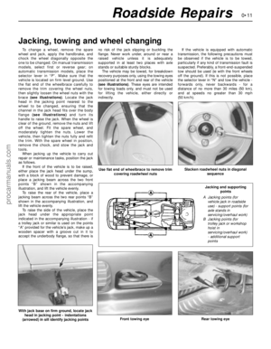 11
11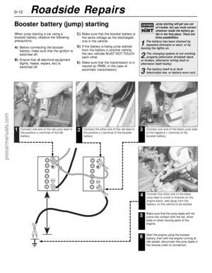 12
12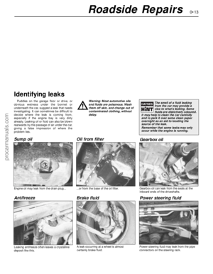 13
13 14
14 15
15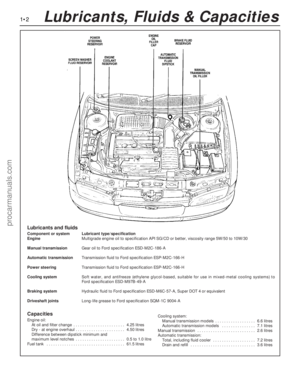 16
16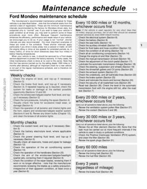 17
17 18
18 19
19 20
20 21
21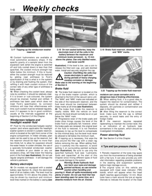 22
22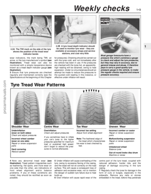 23
23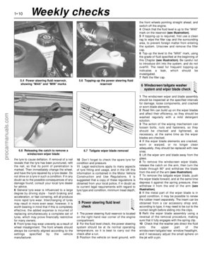 24
24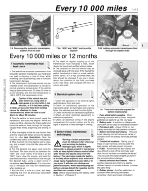 25
25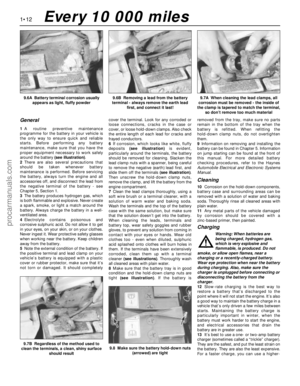 26
26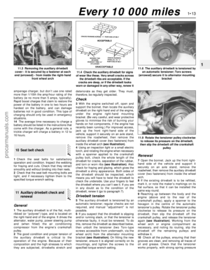 27
27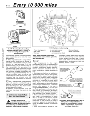 28
28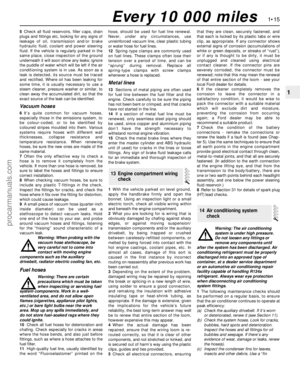 29
29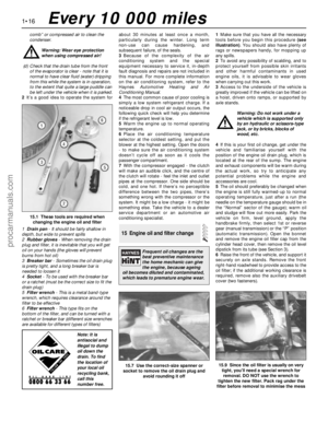 30
30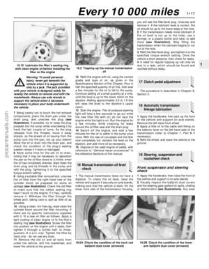 31
31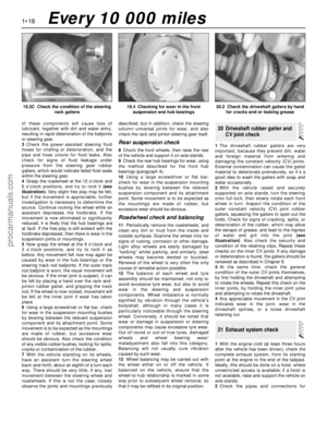 32
32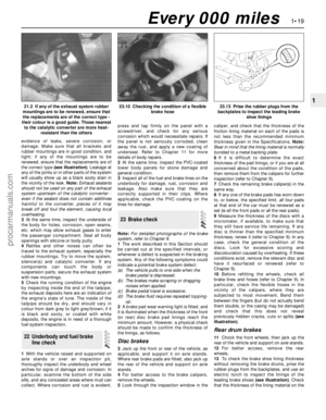 33
33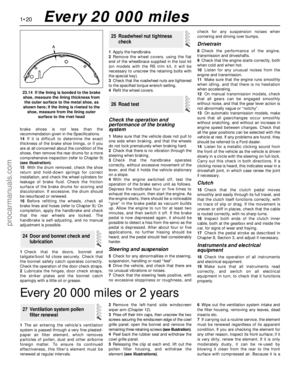 34
34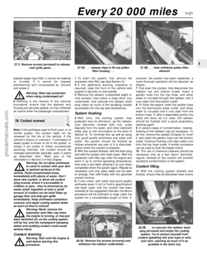 35
35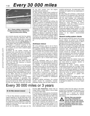 36
36 37
37 38
38 39
39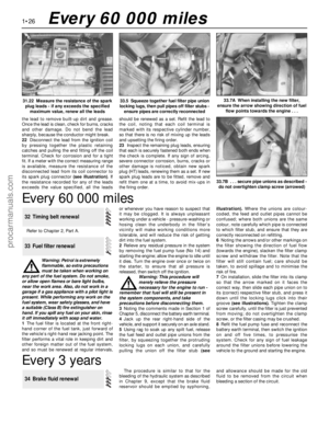 40
40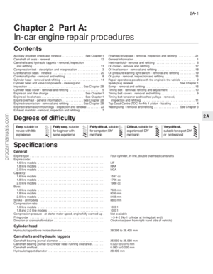 41
41 42
42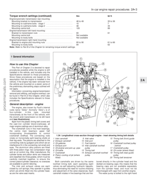 43
43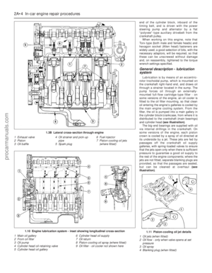 44
44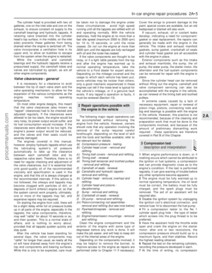 45
45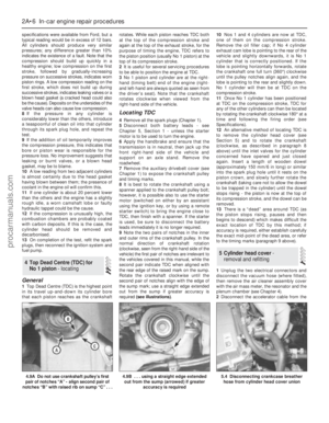 46
46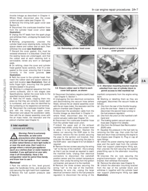 47
47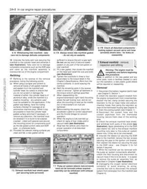 48
48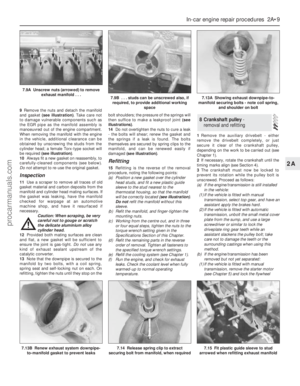 49
49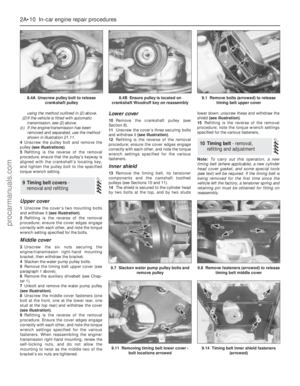 50
50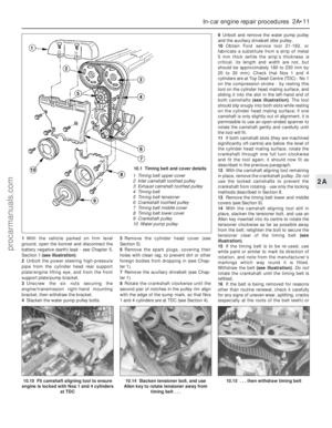 51
51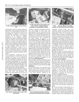 52
52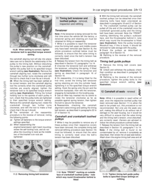 53
53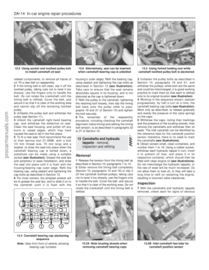 54
54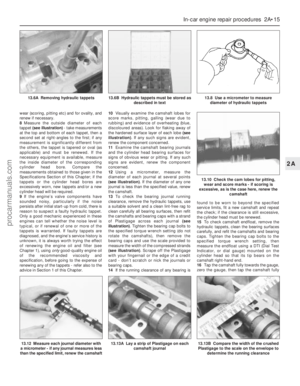 55
55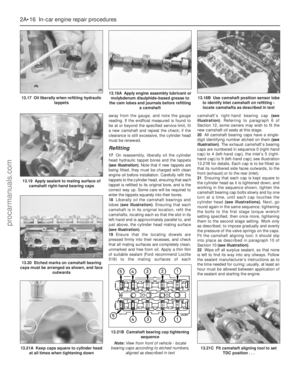 56
56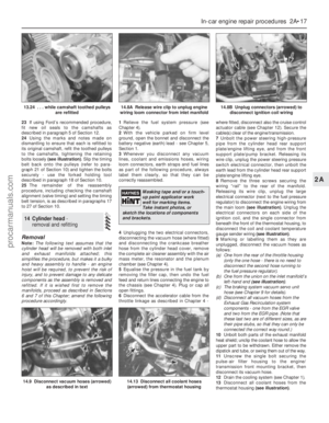 57
57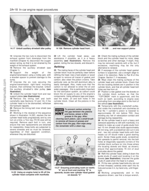 58
58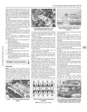 59
59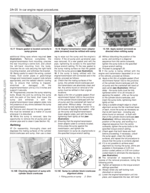 60
60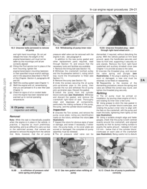 61
61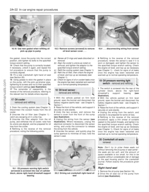 62
62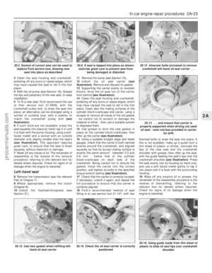 63
63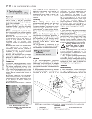 64
64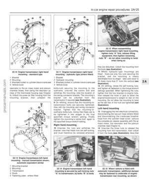 65
65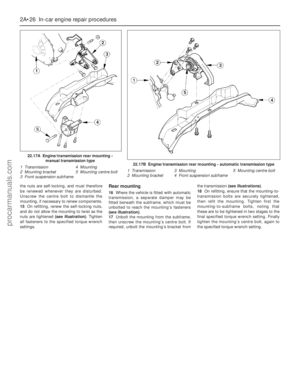 66
66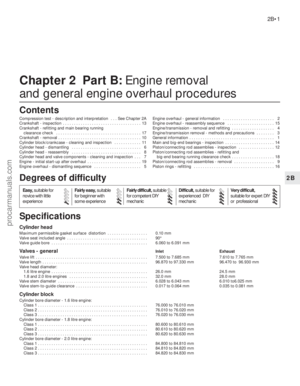 67
67 68
68 69
69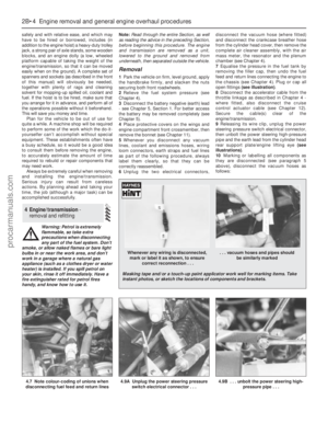 70
70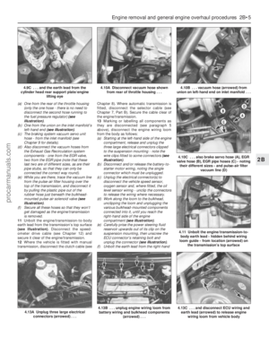 71
71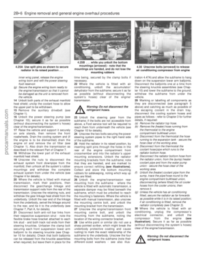 72
72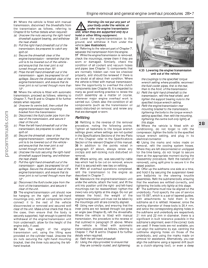 73
73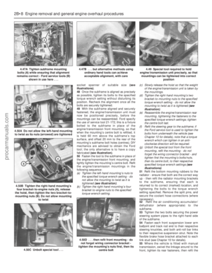 74
74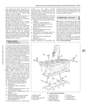 75
75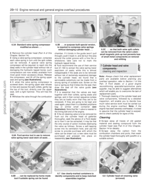 76
76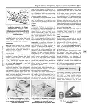 77
77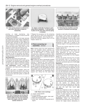 78
78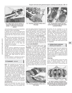 79
79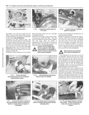 80
80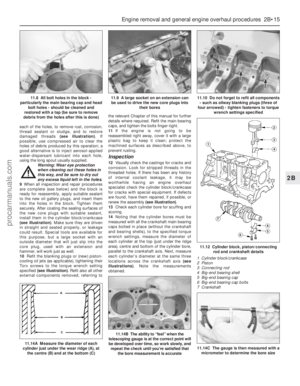 81
81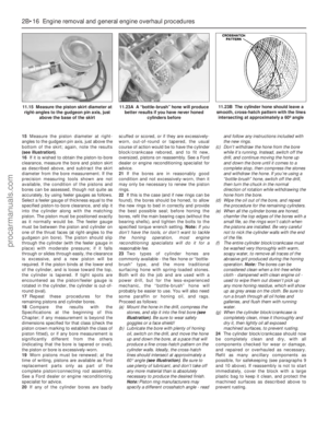 82
82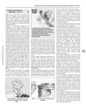 83
83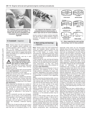 84
84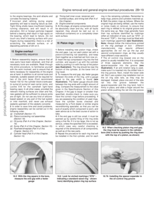 85
85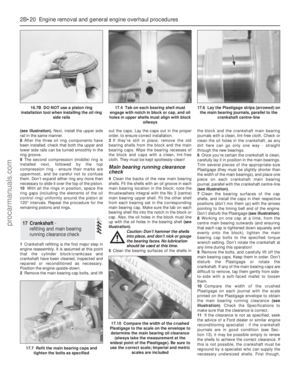 86
86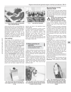 87
87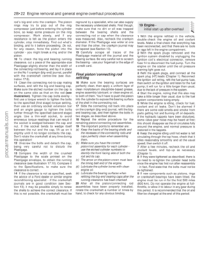 88
88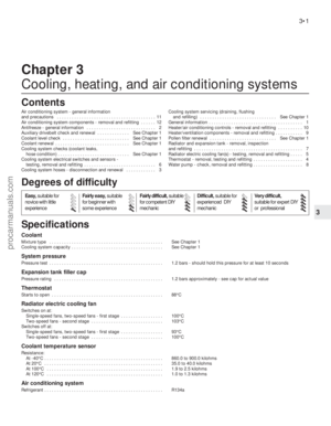 89
89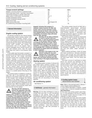 90
90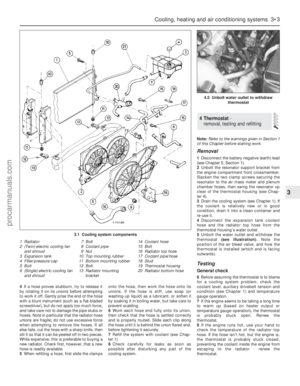 91
91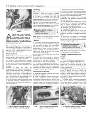 92
92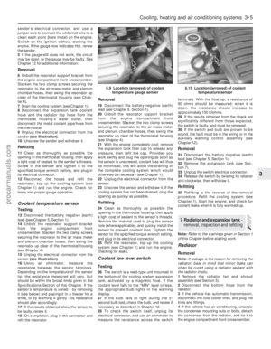 93
93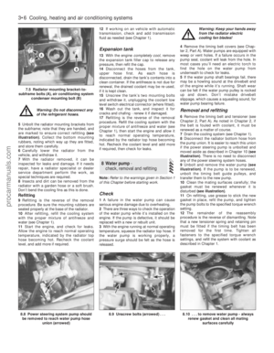 94
94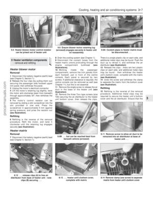 95
95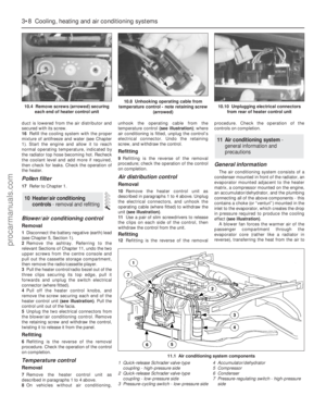 96
96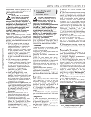 97
97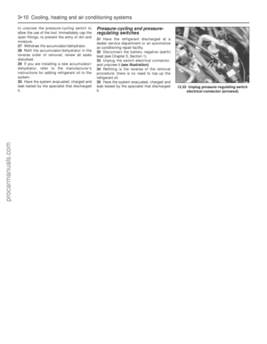 98
98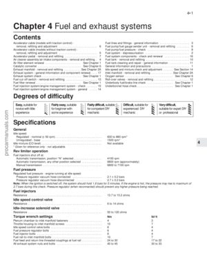 99
99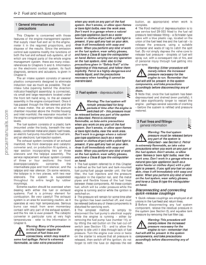 100
100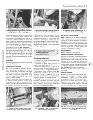 101
101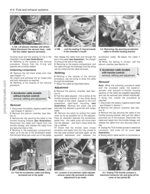 102
102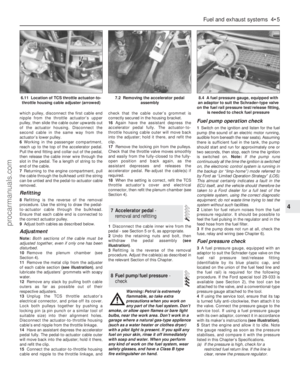 103
103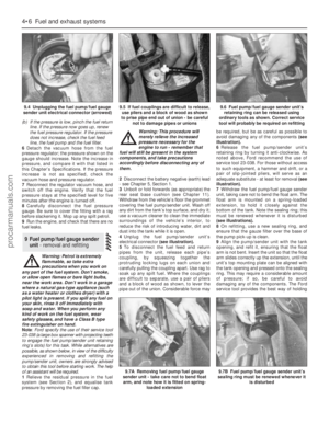 104
104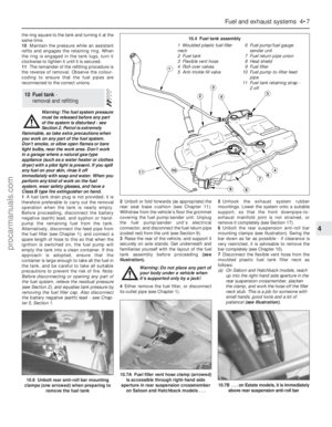 105
105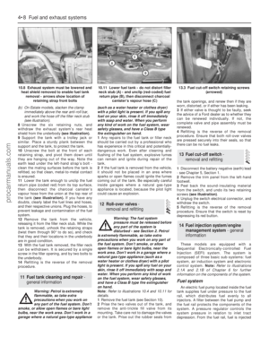 106
106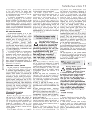 107
107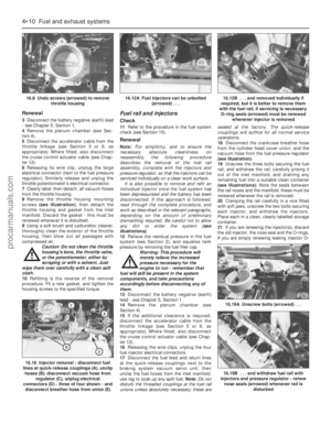 108
108 109
109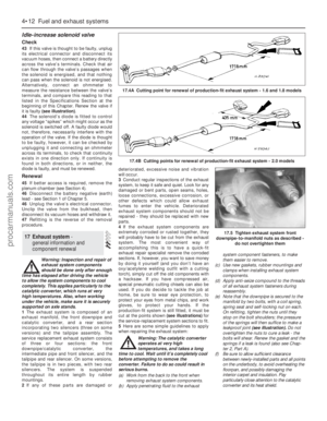 110
110 111
111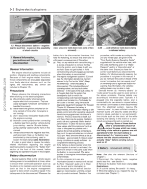 112
112 113
113 114
114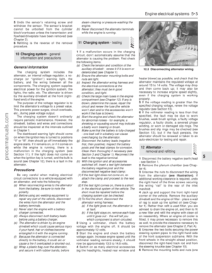 115
115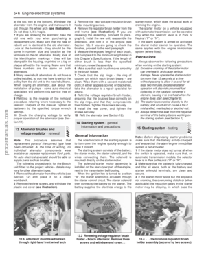 116
116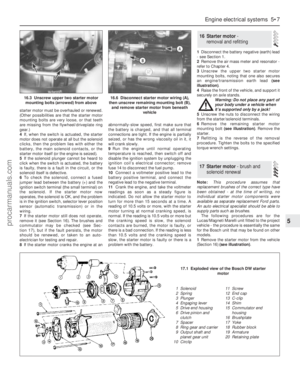 117
117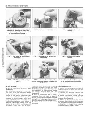 118
118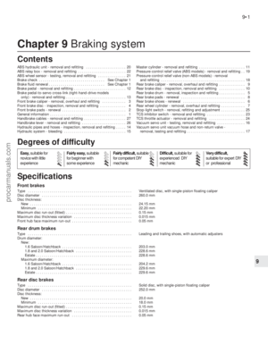 119
119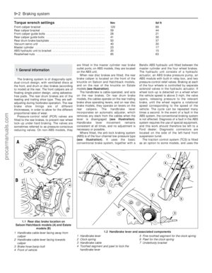 120
120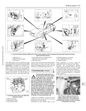 121
121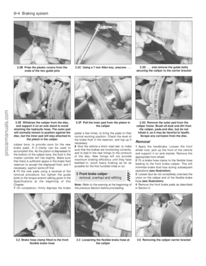 122
122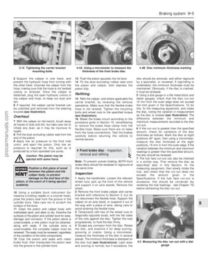 123
123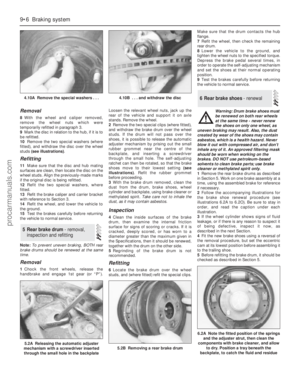 124
124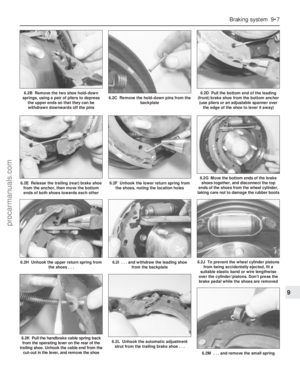 125
125 126
126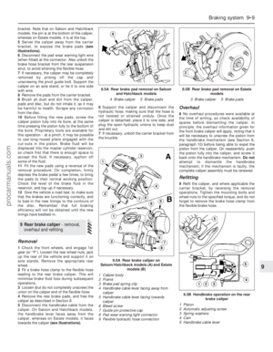 127
127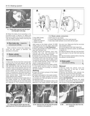 128
128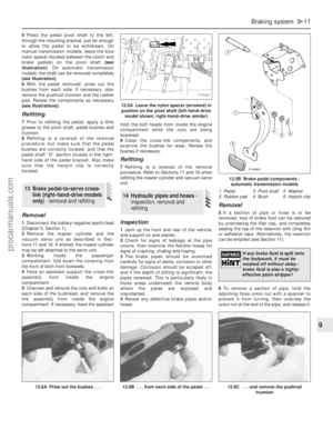 129
129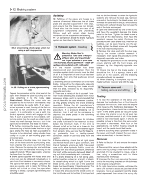 130
130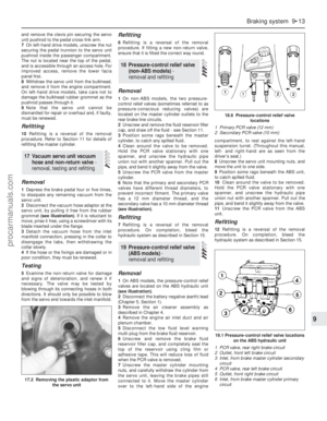 131
131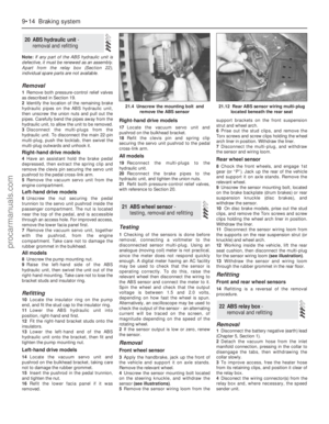 132
132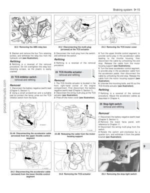 133
133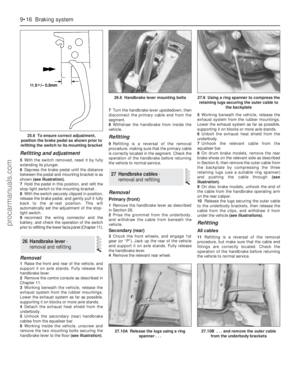 134
134 135
135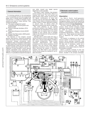 136
136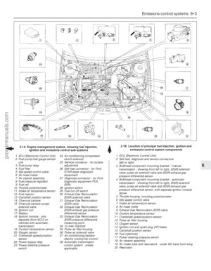 137
137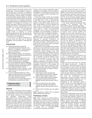 138
138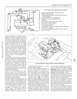 139
139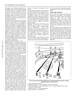 140
140 141
141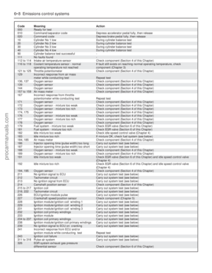 142
142 143
143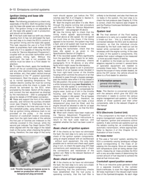 144
144 145
145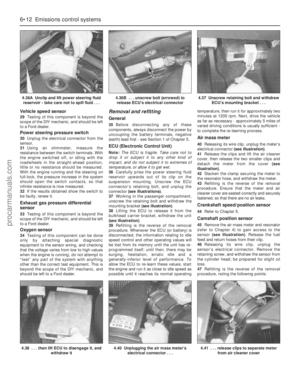 146
146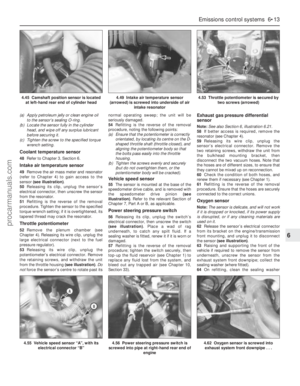 147
147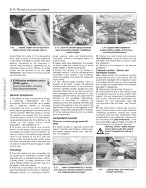 148
148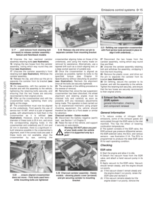 149
149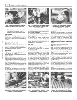 150
150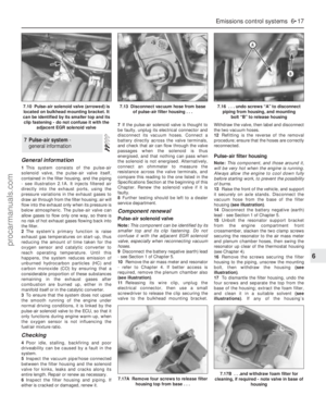 151
151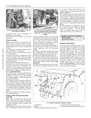 152
152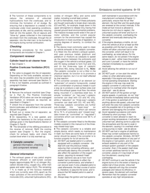 153
153 154
154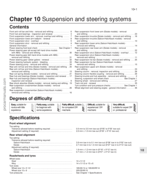 155
155 156
156 157
157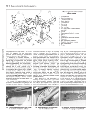 158
158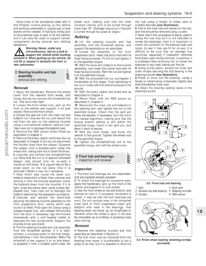 159
159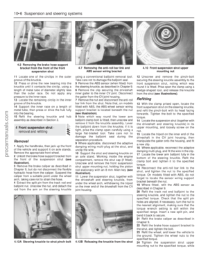 160
160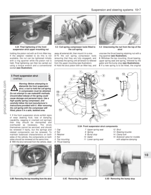 161
161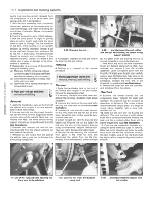 162
162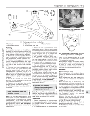 163
163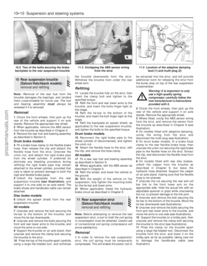 164
164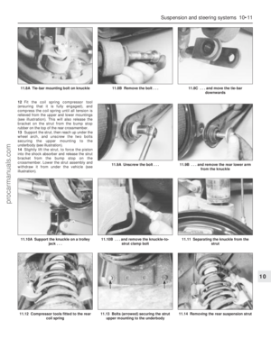 165
165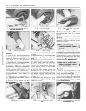 166
166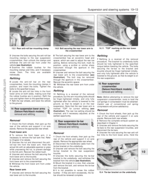 167
167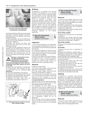 168
168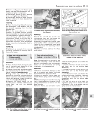 169
169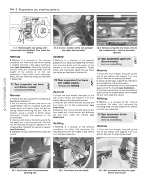 170
170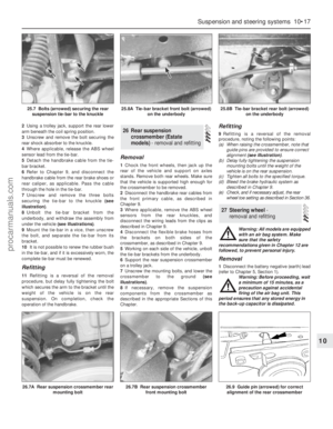 171
171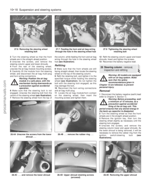 172
172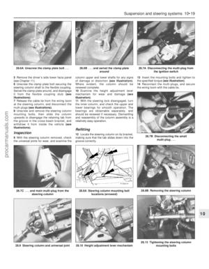 173
173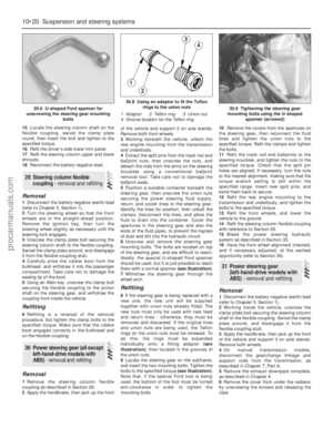 174
174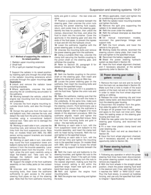 175
175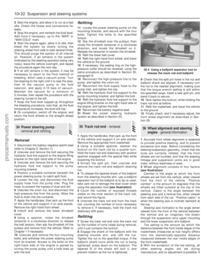 176
176 177
177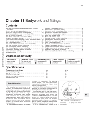 178
178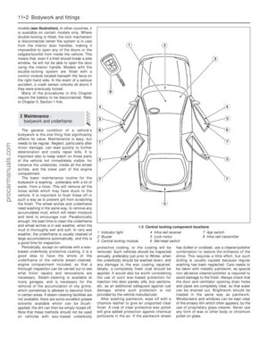 179
179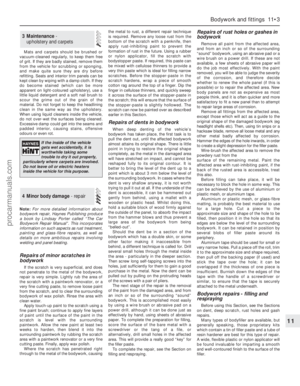 180
180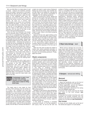 181
181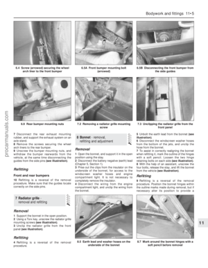 182
182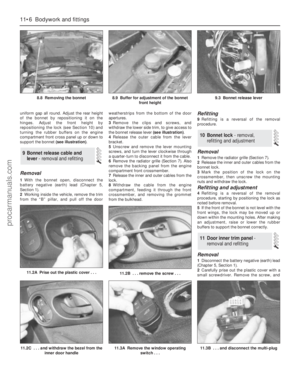 183
183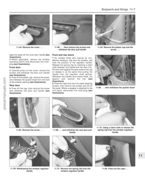 184
184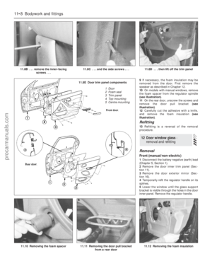 185
185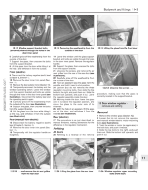 186
186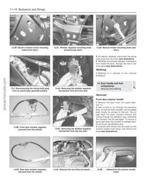 187
187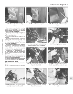 188
188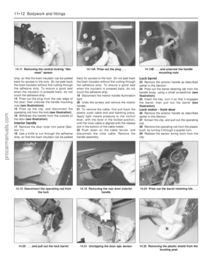 189
189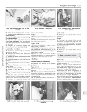 190
190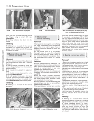 191
191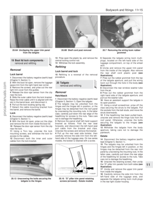 192
192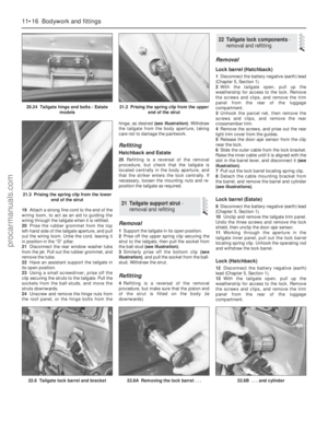 193
193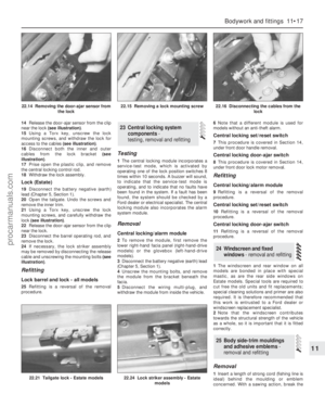 194
194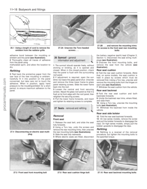 195
195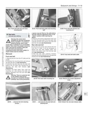 196
196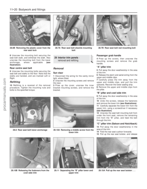 197
197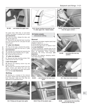 198
198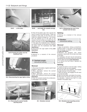 199
199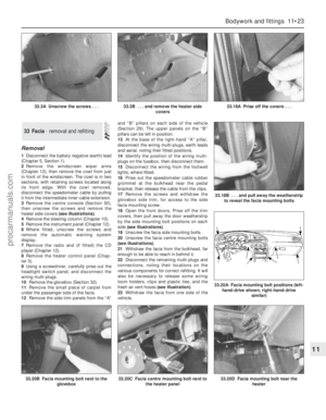 200
200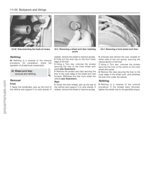 201
201 202
202 203
203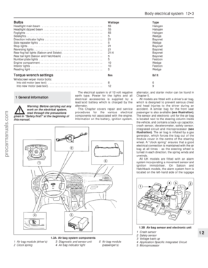 204
204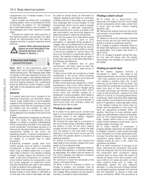 205
205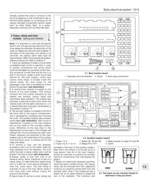 206
206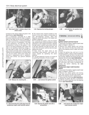 207
207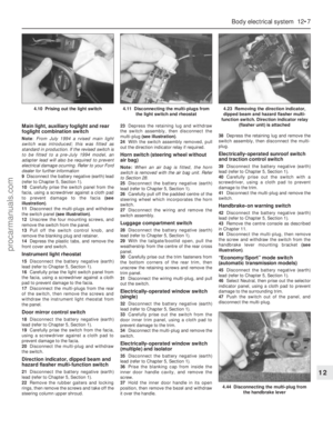 208
208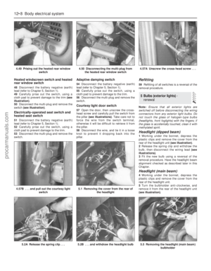 209
209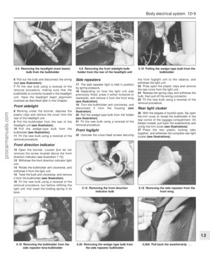 210
210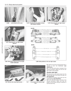 211
211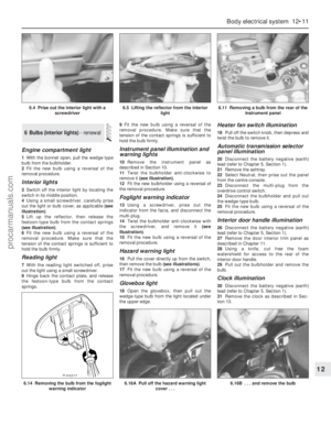 212
212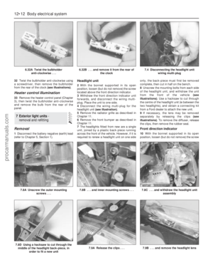 213
213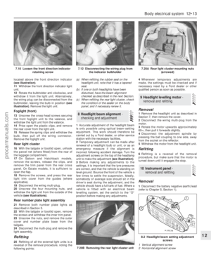 214
214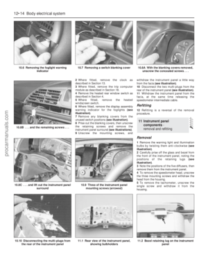 215
215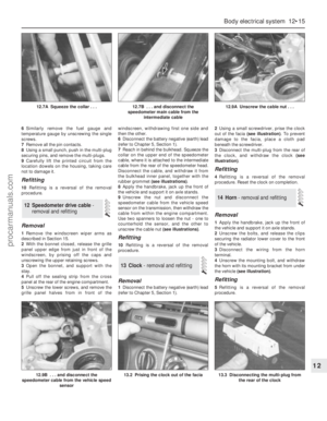 216
216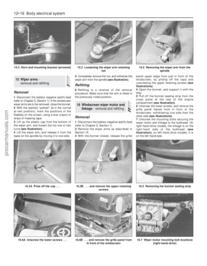 217
217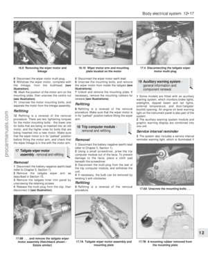 218
218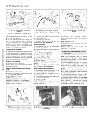 219
219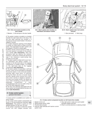 220
220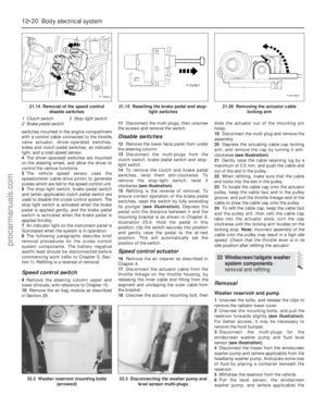 221
221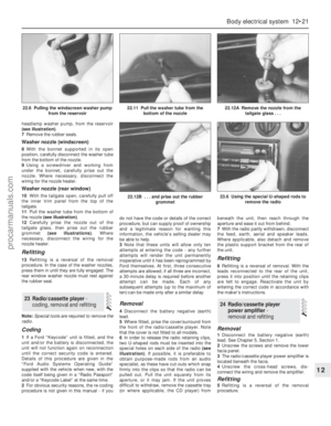 222
222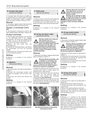 223
223 224
224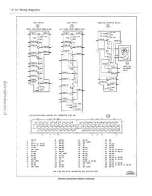 225
225 226
226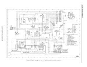 227
227 228
228 229
229 230
230 231
231 232
232 233
233 234
234 235
235 236
236 237
237 238
238 239
239 240
240 241
241 242
242 243
243 244
244 245
245 246
246 247
247 248
248 249
249 250
250 251
251 252
252 253
253 254
254 255
255 256
256 257
257 258
258 259
259 260
260 261
261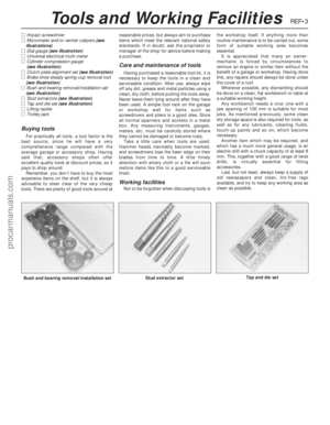 262
262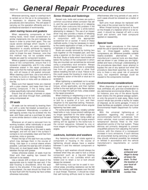 263
263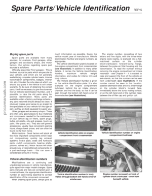 264
264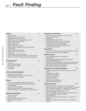 265
265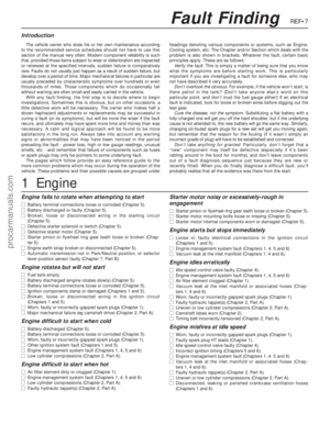 266
266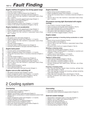 267
267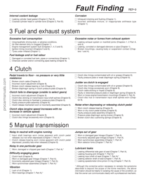 268
268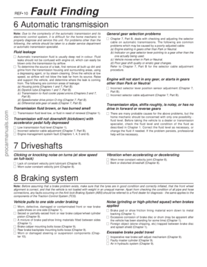 269
269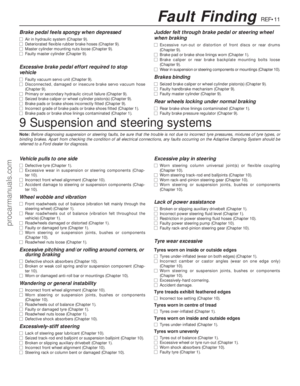 270
270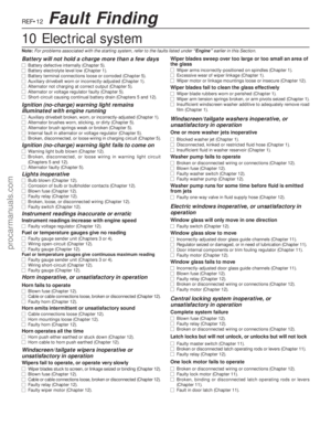 271
271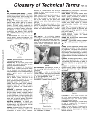 272
272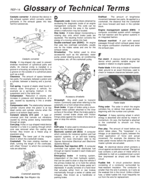 273
273 274
274 275
275 276
276 277
277 278
278