Page 177 of 296

1 General information
The braking system is of the diagonally
split, dual-circuit hydraulic type, with servo
assistance to the front disc brakes and rear
drum brakes. The dual-circuit hydraulic
system is a safety feature - in the event of a
malfunction somewhere in one of the
hydraulic circuits, the other circuit continues
to operate, providing at least some braking
effort. Under normal circumstances, both
brake circuits operate in unison, to provide
efficient braking.
The master cylinder (and the vacuum servo
unit to which it is bolted) is located on the left-
hand side of the bulkhead in the engine
compartment. On all right-hand drive variants,
they are jointly operated via a transverse
cross-link from the brake pedal.
Brake pressure control valves are fitted in-
line to each rear brake circuit, their function
being to regulate the braking force available at
each rear wheel, reducing the possibility of
the rear wheels locking up under heavy
braking. Courier models also have a “light-
laden” valve incorporated into the rear braking
circuits for the same reason. The front brake discs are of the ventilated
type on XR2i and ABS-equipped models, with
solid discs fitted on all other models. The front
brake calipers are of single sliding piston type
mounted on the front spindle carriers each
side. Each rear brake shoe assembly is operated
by a twin-piston wheel cylinder. The leading
brake shoe in each brake unit has a thicker
lining than the trailing shoe, so that they wear
proportionally. To take up the brake
adjustment as the linings wear, each rear
brake assembly incorporates an automatic
adjuster mechanism. The cable-operated handbrake acts on
both rear brakes, to provide an independent
means of brake operation. An anti-lock braking system (ABS) is
available on some models, and has many of
the components in common with the conventional braking system. Further details
on ABS can be found later in this Chapter.
Note:
When servicing any part of the system,
work carefully and methodically; also observe
scrupulous cleanliness when overhauling any
part of the hydraulic system. Always renew
components (in axle sets, where applicable) if
in doubt about their condition, and use only
genuine Ford replacement parts, or at least
those of known good quality. Note the
warnings given in “Safety first” and at relevant
points in this Chapter concerning the dangers
of asbestos dust and hydraulic fluid.
2 Front brake pads - renewal
2
Warning: Disc brake pads MUST
be renewed on both front
wheels at the same time -
NEVER renew the pads on only
one wheel, as uneven braking may result.
The front brake calipers will be of Bendix
or Teves manufacture, and if they or their
component parts require renewal, ensure
that the correct type is fitted. Dust created
by wear of the pads may contain asbestos,
which is a health hazard. Never blow it out
with compressed air, and do not inhale any
of it. DO NOT use petroleum-based
solvents to clean brake parts - use brake
cleaner or methylated spirit only. DO NOT allow any brake fluid, oil or grease to
contact the brake pads or disc. Also refer
to the warning in Section 13 concerning
the dangers of hydraulic fluid.
1
Chock the rear wheels then jack up the
front of the car and support it on axle stands
(see “Jacking and Vehicle Support” ). Remove
the front roadwheels.
2 Hold the caliper support spring with a pair
of pliers, and prise it out of its location in the
caliper housing using a screwdriver (see
illustration) .
3 Prise free the blanking plugs from the
caliper upper and lower mounting bolts.
Unscrew the bolts, then withdraw the caliper
from the anchor bracket (see illustrations).
Suitably support the caliper to avoid straining
the brake hose.
Torque wrench settingsNm lbf ft
Master cylinder to servo . . . . . . . . . . . . . . . . . . . . . . . . . . . . . . . . . . . .\
. 20 to 25 15 to 18
Servo to mounting bracket . . . . . . . . . . . . . . . . . . . . . . . . . . . . . . . . . . . 35 to 45 26 to 33
Pedal-to-servo cross-link brackets to bulkhead . . . . . . . . . . . . . . . . . . 20 to 25 15 to 18
Rear drum/hub to axle flange bolts* . . . . . . . . . . . . . . . . . . . . . . . . . . . . 56 to 76 41 to 56
Caliper-to-spindle carrier (anchor bracket) bolts . . . . . . . . . . . . . . . . . . 50 to 66 37 to 49
Caliper piston housing retaining bolts . . . . . . . . . . . . . . . . . . . . . . . . . . 20 to 25 15 to 18
Load-apportioning valves to bracket . . . . . . . . . . . . . . . . . . . . . . . . . . . 20 to 25 15 to 18
Load-apportioning valve bracket to vehicle . . . . . . . . . . . . . . . . . . . . . . 21 to 28 15 to 21
Load-apportioning valve adjustment screw . . . . . . . . . . . . . . . . . . . . . . 12 to 16 9 to 12
Load-apportioning valve-to-axle beam link rod nut . . . . . . . . . . . . . . . . 21 to 28 15 to 21
Modulator pivot and adjusting clamp bolts . . . . . . . . . . . . . . . . . . . . . . 22 to 28 16 to 21
Modulator drivebelt cover . . . . . . . . . . . . . . . . . . . . . . . . . . . . . . . . . . . .\
8 to 12 6 to 9
Roadwheel nuts . . . . . . . . . . . . . . . . . . . . . . . . . . . . . . . . . . . .\
. . . . . . . 70 to 110 52 to 74
*Applies to all models except Courier. No figures are quoted by the manu\
facturers for Courier models.
9•2 Braking system
2.3b . . . unscrew the bolts then withdraw the caliper from the anchor bracket2.3a Remove the rubber blanking plugs foraccess to the caliper mounting bolts . . .
2.2 Prise out the caliper support spring with a screwdriver
1595Ford Fiesta Remakeprocarmanuals.com
http://vnx.su
Page 178 of 296

4Withdraw the pads from the caliper piston
housing or anchor bracket. The outer pad will
normally remain in position in the anchor
bracket, but the inner pad will stay attached to
the piston in the caliper, and may need to be
carefully prised free. If the old pads are to be
refitted, ensure that they are identified so that
they can be returned to their original
positions.
5 Brush the dust and dirt from the caliper and
piston, but do not inhale it, as it is a health
hazard . Inspect the dust cover around the
piston for damage and for evidence of fluid
leaks, which if found will necessitate caliper
overhaul as described in Section 3.
6 If new brake pads are to be fitted, the
caliper piston will need to be pushed back
into its housing, to allow for the extra pad
thickness - use a C-clamp to do this. Note
that, as the piston is pressed back into the
bore, it will displace the fluid in the system,
causing the fluid level in the brake master
cylinder reservoir to rise and possibly
overflow. To avoid this possibility, a small
quantity of fluid should be removed from the
reservoir. If any brake fluid is spilt onto the
bodywork, hoses or adjacent components in
the engine compartment, wipe it clean without
delay.
7 Prior to refitting, check that the pads and
the disc are clean. Where new pads are to be
installed, peel the protective backing paper
from them. If the old pads are to be refitted,
ensure that they are correctly located as
noted during their removal.
8 Locate the inner and outer brake pad into
position in the caliper. Relocate the caliper
into position on the anchor bracket, and insert
the mounting bolts.
9 Tighten the mounting bolts to the specified
torque, and refit the blanking plugs. Relocate
the caliper support spring.
10 Repeat the procedure on the opposite
front brake. 11
Before lowering the vehicle, check that
the fluid level in the brake master cylinder
reservoir is up to the “Maximum level” mark,
and top-up with the specified fluid type if
required (see “Weekly Checks” ). Depress the
brake pedal a few times to position the pads
against the disc, then recheck the fluid level in
the reservoir and further top-up if necessary.
12 Refit the roadwheels, then lower the
vehicle to the ground. Tighten the roadwheel
retaining nuts to the specified torque.
13 To allow the new brake pads to bed-in
and reach full efficiency, a running-in period of
approximately 100 miles or so should be
observed before hard use and heavy braking.
3 Front brake caliper - removal,
overhaul and refitting
4
Note: Before starting work, refer to the
warning at the beginning of Section 13
concerning the dangers of hydraulic fluid, and
to the warning at the beginning of Section 2
concerning the dangers of asbestos dust.
Removal
1 Chock the rear wheels then jack up the
front of the car and support it on axle stands
(see “Jacking and Vehicle Support” ). Remove
the front roadwheels.
2 Fit a brake hose clamp to the flexible brake
hose leading to the front brake caliper. This
will minimise brake fluid loss during
subsequent operations.
3 Loosen by half a turn, the union on the
caliper end of the flexible brake hose.
4 Remove the front brake pads as described
in Section 2.
5 Support the caliper in one hand, and
prevent the brake hose from turning with a
spanner in the other hand. Unscrew the
caliper from the hose, making sure that the
hose is not twisted unduly or strained (see
illustration) . Once the caliper is detached,
cover or plug the open hydraulic unions to
keep them clean.
6 If required, the caliper anchor bracket can
be unbolted and removed from the spindle
carrier (see illustration) .
Overhaul
7With the caliper on the bench, wipe away all
traces of dust and dirt, but avoid inhaling the
dust, as it is a health hazard .
8 Remove the piston from its bore by
applying low air pressure (from a foot pump,
for example) into the caliper hydraulic fluid
hose port. In the event of a high-pressure air
hose being used, keep the pressure as low as
possible, to enable the piston to be extracted,
but to avoid the piston being ejected too
quickly and being damaged. Position a
suitable piece of wood between the caliper
frame and the piston to prevent this
possibility. Any fluid remaining in the caliper
will probably be ejected with the piston.
9 Using a suitable hooked tool, carefully extract
the dust cover from its groove in the piston
and the seal from its groove in the caliper bore,
but take care not to scratch or damage the
piston and/or the bore in the caliper.
10 Clean all the parts in methylated spirit or
clean brake fluid, and wipe dry using a clean
lint-free cloth (see illustration) . Inspect the
piston and caliper bore for signs of damage,
scuffing or corrosion. If these conditions are
evident, renew the caliper body assembly.
11 If the components are in satisfactory
condition, a repair kit which includes a new
seal and dust cover must be obtained.
12 Lubricate the piston bore in the caliper
and the seal with clean brake fluid. Carefully
fit the seal in the caliper bore, using fingers
only (no tools) to manipulate it into position in
its groove. When in position, check that it is
not distorted or twisted.
13 Locate the dust cover over the piston so
that its inner diameter is engaged in the piston
groove. Smear the area behind the piston
groove with the special lubricating grease
supplied in the repair kit, then insert the piston
into the caliper. Push the piston into position in
the bore, and simultaneously press the dust
cover into the piston housing so that it is seated
correctly. Take particular care not to distort or
damage the seal or cover as they are fitted.
Refitting
14 If the anchor bracket was removed, fit it
into position on the spindle carrier, and tighten
the retaining bolts to the specified torque.
Braking system 9•3
3.10 Brake caliper and piston components
A Dust cover C Piston
B Piston seal D Brake caliper
3.6 Undoing a brake caliper anchor bracket bolt3.5 Hold the brake hose with a spannerand unscrew the caliper from the hose
9
1595Ford Fiesta Remake
An ideal way to remove fluidfrom the master cylinder
reservoir is to use a clean
syringe or an old poultry
baster.
procarmanuals.com
http://vnx.su
Page 179 of 296

15Unplug the hydraulic hose, and check that
the unions are clean. Reconnect the caliper to
the hose so that the hose is not twisted or
strained. The hose union connection can be
fully tightened when the caliper is refitted.
16 Refit the brake pads as described in
Section 2.
17 The brake hydraulic hose can now be fully
tightened. When secured, turn the steering
from lock-to-lock to ensure that the hose
does not foul on the wheel housing or
suspension components.
18 Bleed the brake hydraulic system as
described in Section 13 or 14 according to
type. Providing suitable precautions were
taken to minimise loss of fluid, it should only
be necessary to bleed the relevant front
brake.
19 Refit the roadwheel, lower the vehicle to
the ground, then tighten the wheel nuts to the
specified torque.
4 Front brake disc - inspection,
removal and refitting
2
Note: Before starting work, refer to the
warning at the beginning of Section 2
concerning the dangers of asbestos dust.
Inspection
Note: If a disc requires renewal, BOTH front
discs should be renewed or reground at the
same time to ensure even and consistent
braking. New brake pads should also be fitted.
1 Chock the rear wheels then jack up the
front of the car and support it on axle stands
(see “Jacking and Vehicle Support” ). Remove
the appropriate front roadwheel.
2 Temporarily refit two of the wheel nuts to
diagonally-opposite studs, with the flat sides
of the nuts against the disc. Tighten the nuts
progressively, to hold the disc firmly.
3 Scrape any corrosion from the disc. Rotate
the disc, and examine it for deep scoring,
grooving or cracks. Using a micrometer,
measure the thickness of the disc in several
places. Light wear and scoring is normal, but
if excessive, the disc should be removed, and
either reground by a specialist, or renewed. If regrinding is undertaken, at least the minimum
thickness must be maintained. Obviously, if
the disc is cracked, it must be renewed.
4
Using a dial gauge, check that the disc run-
out, measured at a point 10.0 mm from the
outer edge of the disc, does not exceed the
limit given in the Specifications. To do this, fix
the measuring equipment, and rotate the disc,
noting the variation in measurement as the
disc is rotated (see illustration). The
difference between the minimum and
maximum measurements recorded is the disc
run-out.
5 If the run-out is greater than the specified
amount, check for variations of the disc
thickness as follows. Mark the disc at eight
positions 45° apart, then using a micrometer,
measure the disc thickness at the eight
positions, 15.0 mm in from the outer edge. If
the variation between the minimum and
maximum readings is greater than the
specified amount, the disc should be
renewed.
Removal
6 Remove the caliper and its anchor bracket
with reference to Section 3, but do not
disconnect the hydraulic brake hose.
Suspend the caliper assembly from the front
suspension coil spring, taking care to avoid
straining the brake hose.
7 Remove the wheel nuts which were
temporarily refitted in paragraph 2.
8 Unscrew the screw securing the disc to the
hub, and withdraw the disc (see
illustrations) . If it is tight, lightly tap its rear
face with a hide or plastic mallet.
Refitting
9 Refit the disc in a reversal of the removal
sequence. If new discs are being fitted, first remove their protective coating. Ensure
complete cleanliness of the hub and disc
mating faces and tighten the screw securely.
10
Refit the caliper/anchor bracket with
reference to Section 3.
11 Refit the roadwheel, lower the vehicle to
the ground, and tighten the wheel nuts to the
specified torque.
5 Rear brake drum - removal,
inspection and refitting
2
Note: Before starting work, refer to the
warning at the beginning of Section 6
concerning the dangers of asbestos dust.
Removal
1 Chock the front wheels then jack up the
rear of the car and support it on axle stands
(see “Jacking and Vehicle Support” ). Remove
the appropriate rear roadwheel, and release
the handbrake.
2 Undo the four bolts securing the drum/hub
and stub axle assembly to the rear axle
flange, then withdraw the drum/hub from the
axle. If the brake drum is stuck on the shoes,
remove the rubber access plug from the rear
of the brake backplate, and release the
automatic brake adjuster by levering the
release catch on the adjuster pawl through the
backplate (see illustration) .
3 With the brake drum removed, brush or
wipe the dust from the drum, brake shoes,
9•4 Braking system
5.2 Removing the rubber access plug from
the rear of the brake backplate
4.8b . . . and remove the disc from the hub4.8a Extract the brake disc securing screw . . .4.4 Checking brake disc run-out using a dial gauge
1595Ford Fiesta Remake
If a dial gauge is not
available, check the run-out
by positioning a fixed
pointer near the outer edge,
in contact with the disc face. Rotate
the disc and measure the maximum
displacement of the pointer with feeler
blades.
procarmanuals.com
http://vnx.su
Page 180 of 296

wheel cylinder and backplate. Take great care
not to inhale the dust, as it may contain
asbestos.
4 If required, remove the hub from the drum
as described in Chapter 10.
Inspection
Note: If a brake drum requires renewal, BOTH
rear drums should be renewed at the same
time to ensure even and consistent
braking. New brake shoes should also be
fitted.
5 Clean the inside surfaces of the brake drum
and hub, then examine the internal surface of
the brake drum for signs of scoring or cracks.
If any deterioration of the friction surface is
evident, renewal of the drum is necessary. To
detach the hub from the drum, refer to
Chapter 10.
Refitting
6 Check that the automatic brake adjuster is
fully retracted, then refit the drum/hub to the
axle. Tighten the retaining bolts to the
specified torque.
7 With the brake drum refitted, refit the
roadwheel. Fully depress the brake pedal
several times, to actuate the rear brake
adjuster and take up the adjustment. Check
that the rear wheels spin freely when the
brakes are released, then apply the
handbrake, lower the vehicle and tighten the
wheel nuts to the specified torque.
6 Rear brake shoes - renewal
2
Warning: Drum brake shoes
MUST be renewed on both rear
wheels at the same time -
NEVER renew the shoes on only
one wheel, as uneven braking may result.
Also, the dust created by wear of the
shoes may contain asbestos, which is a
health hazard. Never blow it out with
compressed air, and don’t inhale any of it.
An approved filtering mask should be worn
when working on the brakes. DO NOT use
petroleum-based solvents to clean brake
parts - use brake cleaner or methylated
spirit only.
1 Remove the rear brake drum with reference
to Section 5.
2 Note the fitted positions of the springs and
the adjuster strut.
3 Depress the cups holding the brake shoes
in position and rotate them through 90° to
release them from the locking pins (see
illustration) . Carefully remove the cups and
springs, then withdraw the locking pins from
the rear of the brake backplate.
4 Lift the shoes from their lower pivot and
remove the lower pull-off spring (see
illustration) . Note that on some models anti-
rattle shims may be fitted between the brake
shoe and the lower pivot (see illustration). Iffitted, remove the shims and store them
safely.
5
With the shoe assembly pulled away from
the wheel cylinder, disengage the handbrake
cable from its operating lever on the trailing
shoe (see illustration) .
6 Remove the upper pull-off spring, noting
the method of location.
7 Release the automatic brake adjuster cam
and pawl, then remove the adjuster strut
which is held in position by spring tension
(see illustrations) .
8 Using a screwdriver, lever off the spring clip
securing the handbrake operating lever to the
trailing shoe and separate the assembly (see
illustration) .
Braking system 9•5
6.4b Arrangement of brake shoe anti-
rattle shims - where fitted
A Shims C Lower pull-off spring
B Lower pivot D Brake shoes
6.5 Disengage the handbrake cable from its operating lever on the trailing shoe
6.4a Detach the lower pull-off spring6.3 Depress and turn the cups securing the brake shoes
6.8 Lever off the spring clip securing thehandbrake operating lever to the trailing
shoe6.7b Detach the adjuster strut6.7a Release the automatic brake adjustercam and pawl
9
1595Ford Fiesta Remakeprocarmanuals.com
http://vnx.su
Page 181 of 296

9Detach the automatic brake adjuster
cam in a similar manner to that described
in the previous paragraph, noting its
orientation.
10 Clean the adjuster strut and its associated
components.
11 Clean the backplate, then apply a little
high-melting-point grease to the shoe contact
points on the backplate and the lower anchor
plate (see illustration) . On models so
equipped, refit the anti-rattle shims to the
brake shoe lower pivot on the backplate
ensuring that they are securely located.
12 Fit the handbrake operating lever to the
trailing shoe, using a new spring clip.
13 Fit the automatic brake adjuster cam to
the leading shoe, using a new spring clip.
14 Apply a small amount of high-melting-
point grease to the automatic brake adjuster
cam and pawl contact faces, and where
the cam and handbrake operating lever
sweep across their respective brake shoes.
Do not over-apply, as this may result in lining
contamination in use - a thin smear will
suffice. Take care not to allow any grease to
contact the brake linings.
15 Fit the adjuster strut to the trailing shoe,
securing with its spring, then connect the free
end of the strut to the automatic brake
adjuster cam. Fit the upper pull-off spring
between the tops of the two brake shoes.
16 Reconnect the handbrake cable to its
operating lever.
17 Position the brake shoes onto the
backplate so that their upper leading edges
rest against the wheel cylinder pistons, and
their lower leading edges engage either side
of the lower pivot. Fit the lower pull-off spring
into its locating slots at the bottom end of
each brake shoe.
18 Insert the brake shoe locking pins through
the rear of the backplate, then relocate the
springs and cups. Depress and turn the cups
through 90° to secure.
19 Check that the brake shoes and their
associated components are correctly refitted,
then refit the brake drum with reference to
Section 5.
20 Repeat the procedure on the remaining
rear brake.
7 Rear wheel cylinder -
removal, overhaul and refitting
3
Note: Before starting work, refer to the
warning at the beginning of Section 13
concerning the dangers of hydraulic fluid.
Removal
1 Remove the brake drum as described in
Section 5.
2 Using a suitable hose clamp, isolate the
relevant rear brake unit by clamping its
flexible brake hose.
3 Disconnect the brake pipe at the wheel
cylinder union, and fit a blanking plug to the
brake pipe to prevent dirt ingress.
4 On all models except Courier, drill out the
pop-rivets securing the brake backplate to the
axle flange, and withdraw the backplate
assembly with the brake shoes in situ. Note
that it is not possible to remove the backplate
completely as the handbrake cable will still be
attached to the brake shoes.
5 Expand the brake shoes by pulling their
tops away from the wheel cylinder. The
automatic brake adjuster will hold the shoes
clear of the wheel cylinder for ease of
removal.
6 Remove the single bolt securing the wheel
cylinder to the brake backplate, and withdraw
the wheel cylinder (see illustration).
Overhaul
7Clean any heavy dirt or grease deposits
from the external surfaces of the wheel
cylinder, then pull off the dust-excluding
covers (see illustration) .
8 The pistons and seals will probably shake
out. If they do not, apply air pressure from a
foot-operated tyre pump to the brake pipe
connection to eject them.
9 Examine the surfaces of the pistons and the
cylinder bores for scoring or signs of metal-to-
metal rubbing. If evident, renew the complete
cylinder assembly.
10 If the cylinder is to be renewed, note that three sizes are used across the Fiesta range,
dependent on specification. Ensure that the
new cylinder obtained is of the correct size to
maintain the rear braking balance.
11
Where the pistons and cylinder bores are
in good condition, discard the rubber
seals and dust excluders and obtain a repair
kit.
12 Any cleaning of the components should
be done using clean hydraulic fluid or
methylated spirit - nothing else.
13 Reassemble by dipping the first piston in
clean hydraulic fluid, then manipulate its seal
into position using fingers only. Ensure that
the seal is fitted correctly with its raised lip
facing away from the brake shoe bearing face
of the piston.
14 Insert the first piston into the wheel
cylinder from the opposite end of the cylinder
body. With it located in position, fit a dust-
excluding cover to it.
15 Fit the seal to the second piston, as
described in paragraph 13, then insert the
spring to the wheel cylinder, followed by the
second piston. Take care not to damage the
lip of the seal when fitting to the wheel
cylinder - additional lubrication with clean
hydraulic fluid and a slight twisting action
may help. Once again, only fingers should be
used.
16 Fit the dust excluding cover to the second
piston.
Refitting
17 Refitting is the reverse sequence to
removal. When refitting the backplate, locate
it in position and temporarily insert the
hub/drum retaining bolts to ensure correct
alignment. Now secure the brake backplate
using new pop rivets. Release the automatic
brake adjuster so that the brake shoes are
brought into contact with the wheel cylinder,
before refitting the hub/drum assembly as
described in Section 5.
18 On completion, bleed the brake hydraulic
system as described in Section 13 or 14 (as
applicable).
9•6 Braking system
7 .7 Exploded view of rear wheel cylinder
components
A Dust cap E Piston
B Bleed screw F Seal
C Wheel cylinder G Spring
D Dust-excluding cover7.6 Rear view of brake backplate
A Wheel cylinder-to-brake backplate retaining bolt
B Wheel cylinder brake pipe connection
C Bleed screw
6.11 Brake shoe contact points on brake backplate (arrowed)
1595Ford Fiesta Remakeprocarmanuals.com
http://vnx.su
Page 182 of 296

8 Rear brake backplate-
removal and refitting
3
Removal
1 Remove the brake drum/hub assembly as
described in Section 5.
2 Remove the rear brake shoes as described
in Section 6.
3 Compress the three retaining lugs, and
release the handbrake cable from the
backplate by pushing it back through the
plate (see illustration) .
4 Using a suitable hose clamp, isolate the
relevant rear brake unit by clamping its
flexible brake hose.
5 Disconnect the brake pipe at the wheel
cylinder union, and fit blanking plugs to
prevent dirt ingress.
6 Drill out the pop-rivets securing the
backplate to the rear axle, and remove the
backplate (see illustration) .
7 Remove the single bolt securing the wheel
cylinder to the brake carrier plate, and
withdraw the wheel cylinder.
8 If required, remove the handbrake
adjustment plunger from the backplate by
gently prising the spring off, over the plunger
abutment, then withdraw the plunger from the
brake shoe side (see illustration) . Remove the
plunger collar from the rear of the backplate.
Refitting
9 Locate the wheel cylinder in positionand
securely tighten the retaining bolt. 10
If removed, refit the handbrake
adjustment plunger to the backplate.
11 Place the backplate in position and
temporarily insert the hub/drum retaining
bolts to ensure correct alignment. Now secure
the brake backplate using new pop rivets
12 Refit the handbrake cable, and ensure
that the retaining lugs are secure.
13 Connect the brake pipe to the wheel
cylinder and remove the brake hose clamp.
14 Refit the rear brake shoes as described in
Section 6.
15 Refit the brake drum/hub as described in
Section 5.
16 On completion, bleed the brake hydraulic
system as described in Section 13 or 14 (as
applicable).
9 Master cylinder - removal,
overhaul and refitting
3
Note: Before starting work, refer to the
warning at the beginning of Section 13
concerning the dangers of hydraulic fluid.
Removal
1 Disconnect the wiring multi-plug from the
fluid level warning indicator in the reservoir
filler cap, then remove the filler cap from the
reservoir. Note that the filler cap must not be
inverted. The brake fluid should now be
removed from the reservoir.
2 Identify each brake pipe and its connection
to the master cylinder. Unscrew the fluid pipe to master cylinder union nuts and disconnect
the pipes. On models equipped with anti-lock
brakes, disconnect the modulator return
hoses from the brake fluid reservoir, collecting
fluid spillage from the hoses in a suitable tray
(see illustration)
. The modulator return hose
unions should be disconnected by first
pushing the hose into the reservoir, then
retaining the collar against the reservoir body
whilst withdrawing the hose. Note that the
modulator return hoses are colour coded - the
left-hand modulator has a black return hose
and connector, and should be fitted to the
forward section of the reservoir, whilst the
right-hand modulator has a grey return hose
and connector, and should be fitted to the
rear section of the reservoir.
3 Unscrew the mounting nuts and withdraw
the master cylinder from the servo unit.
Overhaul
4 With the master cylinder removed, empty
any remaining fluid from it, and clean it
externally.
5 Withdraw the brake fluid reservoir from the
top of the master cylinder by pulling and
rocking it free from its retaining seals (see
illustration) .
6 Extract the reservoir seals from the top face
of the master cylinder (see illustration).
Braking system 9•7
8.8 Handbrake adjustment plunger
A Plunger B Spring C Collar8.6 Drilling out a pop-rivet securing the brake backplate to the axle flange8.3 Compress the retaining lugs (arrowed),and release the handbrake cable from the backplate
9.5 Removing the brake fluid reservoirfrom its seals in the master cylinder
9.2 Modulator return hose connections at the brake fluid reservoir
A Return hoses B Collars
9
1595Ford Fiesta Remake 9.6 Brake fluid reservoir seal
An ideal way to remove fluid
from the master cylinder
reservoir is to use a clean
syringe or an old poultry
baster.
procarmanuals.com
http://vnx.su
Page 183 of 296

7Using a suitable socket, firmly press the
primary piston into the master cylinder until
the secondary piston retaining pin becomes
visible through the secondary piston reservoir
opening. Remove the retaining pin using
needle-nosed pliers or similar tool (see
illustration) .
8 Remove the primary and secondary pistons
by shaking or gently tapping the master
cylinder (see illustrations) .
9 Examine the piston and cylinder bore
surfaces for scoring or signs of metal-to-metal
rubbing. If evident, renew the master cylinder
assembly as a complete unit.
10 Cleaning of components should be done
using clean brake hydraulic fluid or
methylated spirit - nothing else.
11 Obtain a master cylinder repair kit, and
brake fluid reservoir seals.
12 Having dipped the secondary piston
assembly in clean hydraulic fluid, insert it into
the master cylinder. Note that the seals on the
secondary piston have raised lips which face
away from each other, towards the extremities
of the piston (see illustration) . A slight
twisting action will assist insertion.
13 Using a suitable socket bar extension, or
similar tool, press the secondary piston into
the master cylinder to enable fitting of the
secondary piston retaining pin. 14
Dip the primary piston assembly in clean
hydraulic fluid and, using a similar twisting
action to that used for the secondary piston,
insert it into the master cylinder. Note that
both the seals fitted to the primary piston
have raised lips that face the same way -
towards its captive spring.
15 Insert new brake fluid reservoir seals to
the master cylinder then, using a similar rolling
action to that used to remove it, fit the
reservoir to the master cylinder.
16 It is recommended that a small quantity of
fluid is now poured into the reservoir and the
pistons depressed several times to prime the
unit.
Refitting
17 Locate the master cylinder to the servo
unit, having fitted a new dust cover as
applicable. Refit the two spring washers and
nuts, then tighten to the specified torque.
18 Remove the blanking plugs fitted on
removal of the unit, then reconnect the brake
pipes, tightening the unions securely.
Additionally, on vehicles equipped with anti-
lock brakes, reconnect the modulator return
hoses to the brake fluid reservoir in
accordance with their colour coding (see
paragraph 2), pushing the hoses firmly into
the reservoir body then levering out the collars
to retain. 19
Refill the brake fluid reservoir with fresh
fluid of the specified type, then bleed the
braking system in accordance with Section 13
or 14, as applicable.
20 On completion, ensure that the brake fluid
level is up to the MAX mark on the reservoir
before refitting the reservoir cap and the
warning indicator wiring multi-plug.
10 Brake pedal -
removal and refitting
1
Removal
1 Disconnect the battery negative (earth) lead
(refer to Chapter 5A, Section 1).
2 Remove the clip securing the brake servo
operating link pushrod to the brake pedal,
noting the bush fitted in the pedal, and
disconnect the brake stop light switch wiring
connector. Release the brake stop light switch
in a clockwise direction, and extract it from
the pedal bracket.
3 Remove the C-clip from its pedal shaft
location, at the right-hand side of the brake
pedal, to allow the shaft to be withdrawn
towards the centre of the vehicle.
4 As the pedal shaft is withdrawn, remove the
brake pedal from the servo operating link
pushrod. The brake pedal spacer can now be
slid off the shaft if required, and the brake rod
bush removed.
5 Prise the bushes out from both sides of the
brake pedal, and renew as necessary.
Refitting
6 Prior to refitting, apply a small amount of
molybdenum disulphide grease to the pedal
shaft.
7 Refitting is the reverse sequence to
removal, ensuring that the brake rod bush is
located correctly, and that the pedal shaft “D”
section locates into the pedal box right-hand
support.
8 When refitting the stop light switch, insert
the switch into its retainer, press it lightly
against the brake pedal until all free play is
just taken up, then turn the switch clockwise
to secure. Reconnect the switch wiring
connector.
9•8 Braking system
9 .12 Exploded view of master cylinder components
A Brake fluid reservoir
B Reservoir seals
C Secondary piston retaining pin D Master cylinder
E Secondary piston
F Primary piston
9.8b . . . followed by the secondary piston
assembly9.8a Removing the primary piston
assembly from the master cylinder . . .9.7 Removing the secondary piston retaining pin
1595Ford Fiesta Remakeprocarmanuals.com
http://vnx.su
Page 184 of 296
 lead
(refer to Chapter 5A, Section 1).
2 Disconnect the cross link pushrod from its
brake")
11 Brake pedal-to-servo cross-link - removal and refitting
3
Removal
1Disconnect the battery negative (earth) lead
(refer to Chapter 5A, Section 1).
2 Disconnect the cross link pushrod from its
brake pedal location by removing the retaining
clip on the brake pedal, noting the bush fitted
in the pedal.
3 Disconnect the wiring multi-plug from the
fluid level warning indicator in the master
cylinder reservoir filler cap, then remove the
filler cap. Note that the filler cap must not be
inverted. The brake fluid should now be
removed from the reservoir.
4 Identify each brake pipe and its connection
to the master cylinder. Unscrew the fluid pipe
to master cylinder union nuts and disconnect
the pipes. On models equipped with anti-lock
brakes, disconnect the modulator return
hoses from the brake fluid reservoir, collecting
fluid spillage from the hoses in a suitable tray.
The modulator return hose unions should be
disconnected by first pushing the hose into
the reservoir, then retaining the collar against
the reservoir body whilst withdrawing the
hose. Note that the modulator return hoses
are colour coded - the left-hand modulator
has a black return hose and connector, and
should be fitted to the forward section of the
reservoir, whilst the right-hand modulator has
a grey return hose and connector, and should
be fitted to the rear section of the reservoir.
5 Disconnect the vacuum hose from the
servo unit by carefully levering between the
hose connector and the servo housing collar
with a screwdriver.
6 Lift up the flap of sound insulation on the bulkhead, in the passenger side footwell, to
expose the servo mounting bracket retaining
nuts, and remove them
(see illustration).
7 Remove the four nuts securing the servo
unit to its mounting bracket assembly.
8 Pull the servo/master cylinder assembly
forward and remove the inner servo support
bracket.
9 Remove the spring clip and clevis pin
securing the servo actuating rod to the cross
link, then lift out the servo/master cylinder
assembly.
10 Remove the two nuts on the right-hand
side of the pedal box assembly to free the
cross link right-hand support bracket, then
withdraw the link from the vehicle (see
illustration) .
Refitting
11Refitting is the reverse procedure to
removal, ensuring that the brake pedal
pushrod grommet is seated correctly in the
bulkhead and that the pushrod itself locates
through the brake pedal before securing the
servo operating link support brackets. Ensure
correct location of the pushrod bush in the
brake pedal.
12 Bleed the complete brake hydraulic
system in accordance with Section 13 or 14
(as applicable).
12 Hydraulic pipes and hoses -
renewal
2
Note: Before starting work, refer to the
warning at the beginning of Section 13
concerning the dangers of hydraulic fluid.
1 If any pipe or hose is to be renewed,
minimise hydraulic fluid loss by disconnecting
the wiring multi-plug from the fluid level
warning indicator in the master cylinder
reservoir filler cap, then remove the filler cap.
Note that the filler cap must not be inverted.
Place a piece of plastic film over the reservoir
and seal it with an elastic band. Alternatively,
flexible hoses can be sealed, if required, using
a proprietary brake hose clamp; metal brake pipe unions can be plugged (if care is taken
not to allow dirt into the system) or capped
immediately they are disconnected. Place a
wad of rag under any union that is to be
disconnected, to catch any spilt fluid.
2
If a flexible hose is to be disconnected,
unscrew the brake pipe union nut before
removing the spring clip which secures the
hose to its mounting (see illustration). Where
the other end of the hose is connected
directly to the brake caliper, disconnect it by
unscrewing it from its tapped hole.
3 To unscrew the union nuts, it is preferable to
obtain a brake pipe spanner of the correct size;
these are available from most large motor
accessory shops. Failing this, a close-fitting
open-ended spanner will be required, though if
the nuts are tight or corroded, their flats may be
rounded-off if the spanner slips. In such a case,
a self-locking wrench is often the only way to
unscrew a stubborn union, but it follows that
the pipe and the damaged nuts must be
renewed on reassembly. Always clean a union
and surrounding area before disconnecting it. If
disconnecting a component with more than
one union, make a careful note of the
connections before disturbing any of them.
4 If a brake pipe is to be renewed, it can be
obtained, cut to length and with the union
nuts and end flares in place, from Ford
dealers. All that is then necessary is to bend it
to shape, following the line of the original,
before fitting it to the car. Alternatively, most
motor accessory shops can make up brake
pipes from kits, but this requires very careful
measurement of the original, to ensure that
the replacement is of the correct length. The
safest answer is usually to take the original to
the shop as a pattern.
5 Before refitting, blow through the new pipe
or hose with dry compressed air. Do not
overtighten the union nuts. It is not necessary
to exercise brute force to obtain a sound joint.
6 If flexible rubber hoses are renewed, ensure
that the pipes and hoses are correctly routed,
with no kinks or twists, and that they are
secured in the clips or brackets provided.
7 After fitting, bleed the hydraulic system as
described in Section 13 or 14 (as applicable),
wash off any spilt fluid, and check carefully for
fluid leaks.
Braking system 9•9
12.2 Prising out a spring retaining clip from a rigid pipe/flexible hose support bracket11.10 Exploded view of brake pedal-to-
servo cross link and its retaining brackets11.6 Servo mounting bracket retaining nuts
A Inner section retaining nuts
B Outer section retaining nuts
9
1595Ford Fiesta Remake
An ideal way to remove fluid from the master cylinder
reservoir is to use a clean
syringe or an old poultry
baster.
procarmanuals.com
http://vnx.su
 1
1 2
2 3
3 4
4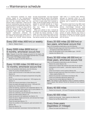 5
5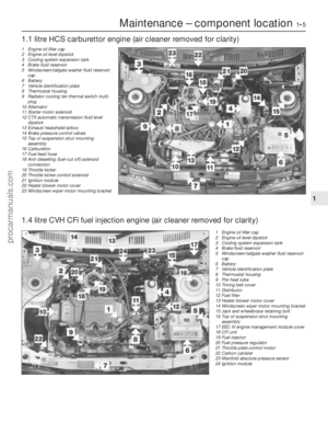 6
6 7
7 8
8 9
9 10
10 11
11 12
12 13
13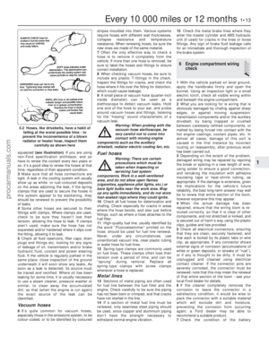 14
14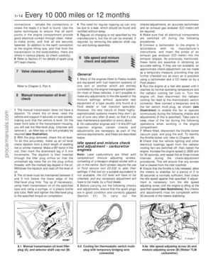 15
15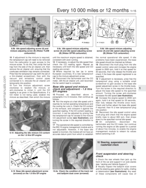 16
16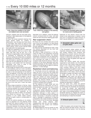 17
17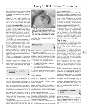 18
18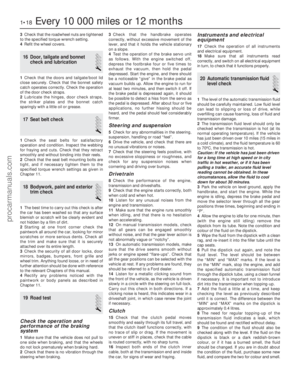 19
19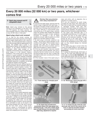 20
20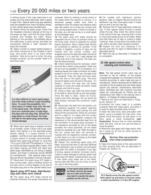 21
21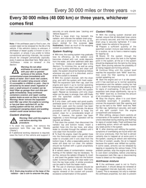 22
22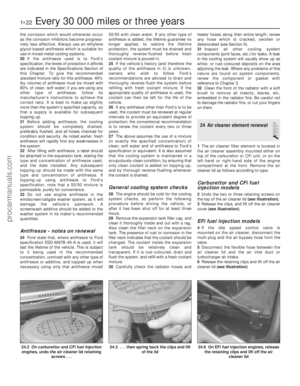 23
23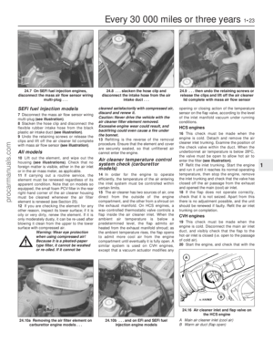 24
24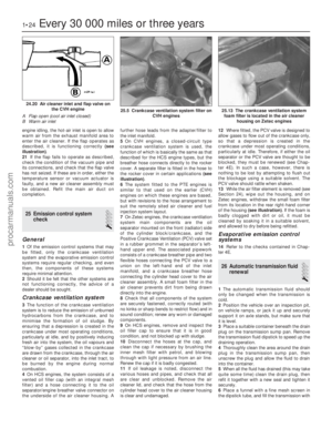 25
25 26
26 27
27 28
28 29
29 30
30 31
31 32
32 33
33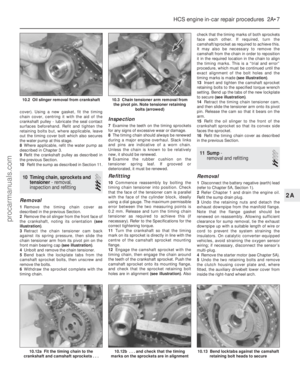 34
34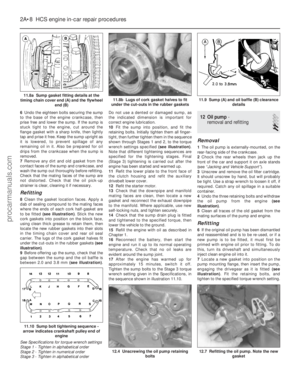 35
35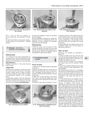 36
36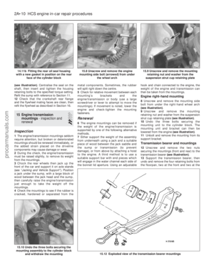 37
37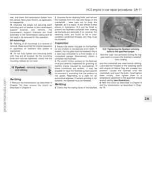 38
38 39
39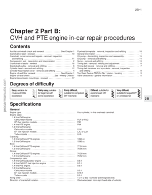 40
40 41
41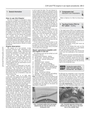 42
42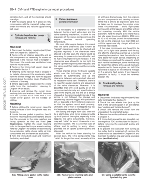 43
43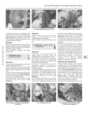 44
44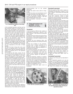 45
45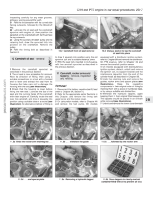 46
46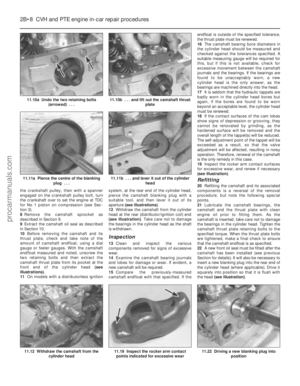 47
47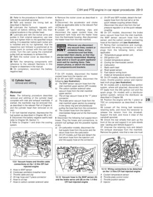 48
48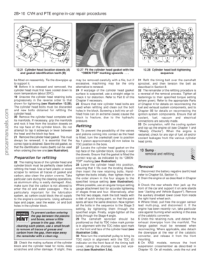 49
49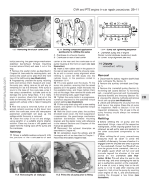 50
50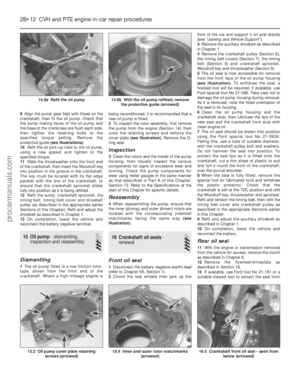 51
51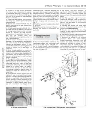 52
52 53
53 54
54 55
55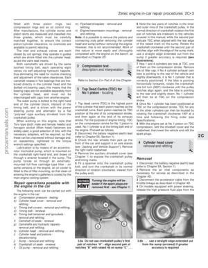 56
56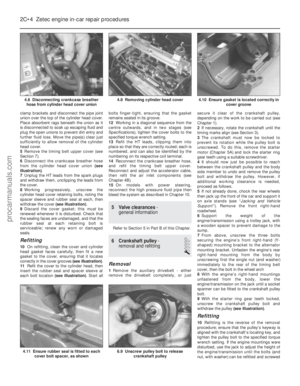 57
57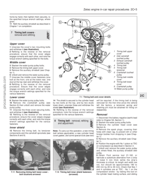 58
58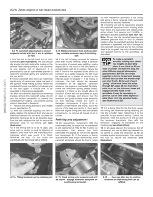 59
59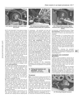 60
60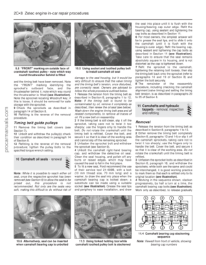 61
61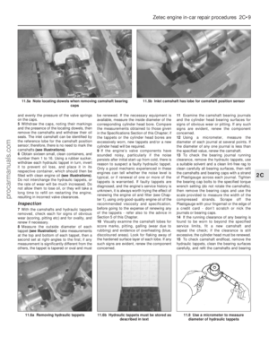 62
62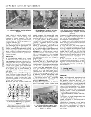 63
63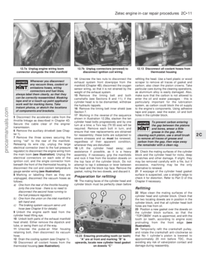 64
64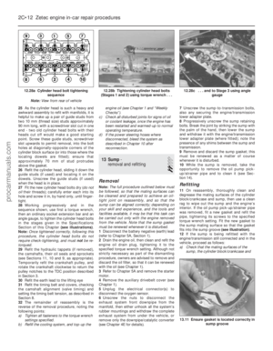 65
65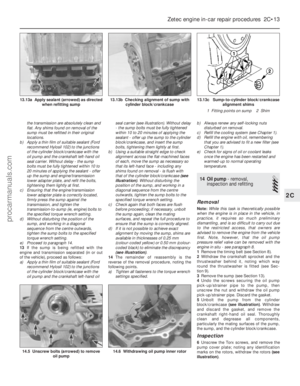 66
66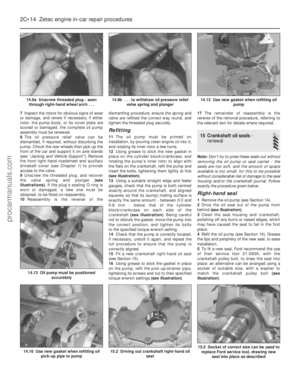 67
67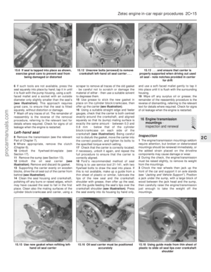 68
68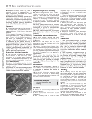 69
69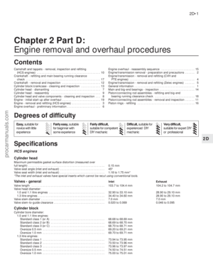 70
70 71
71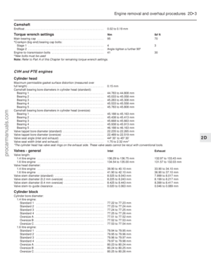 72
72 73
73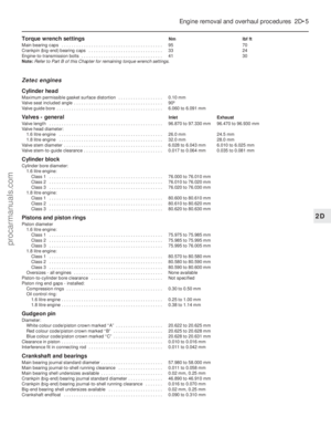 74
74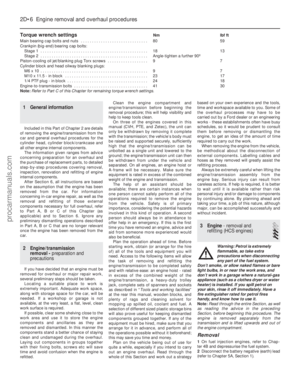 75
75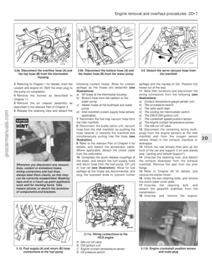 76
76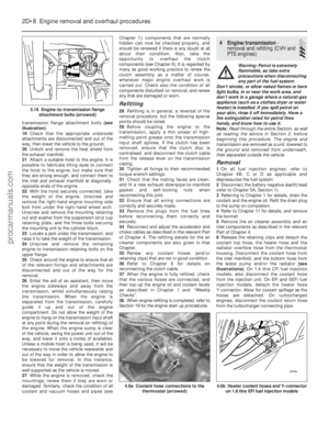 77
77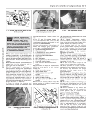 78
78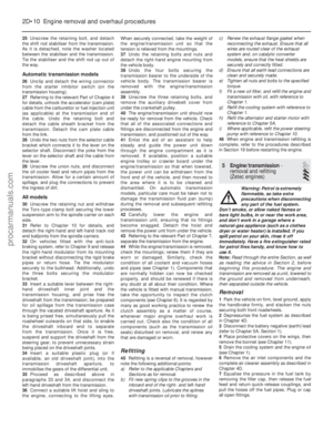 79
79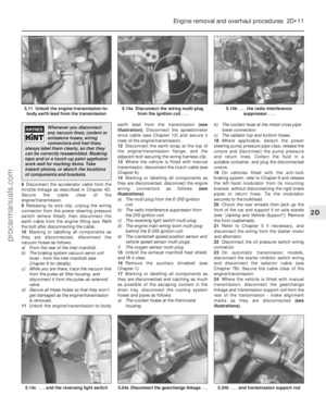 80
80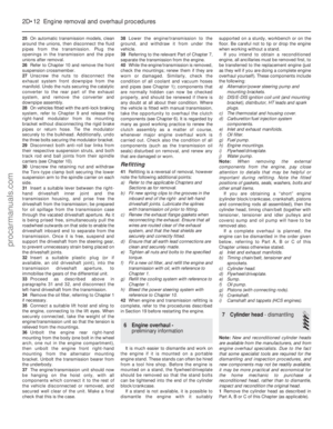 81
81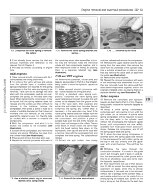 82
82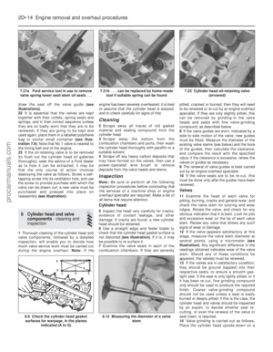 83
83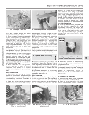 84
84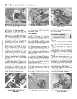 85
85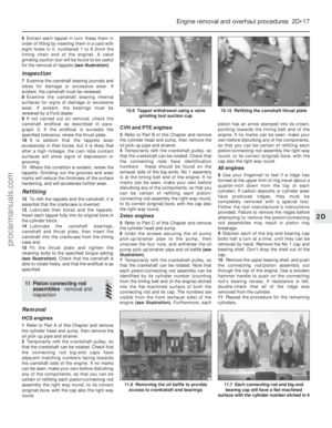 86
86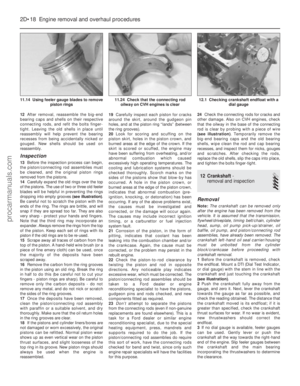 87
87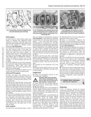 88
88 89
89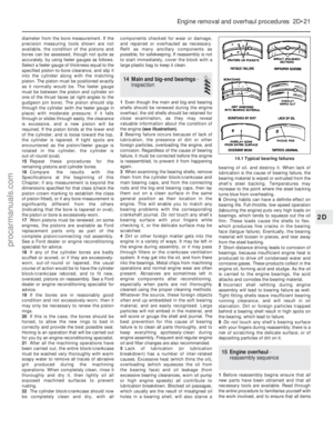 90
90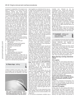 91
91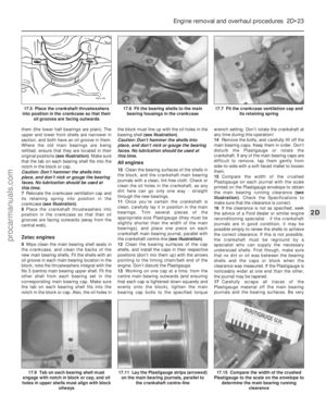 92
92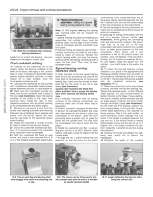 93
93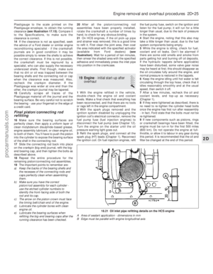 94
94 95
95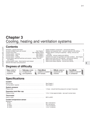 96
96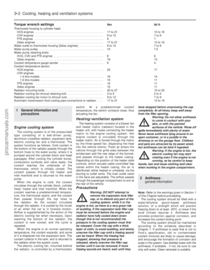 97
97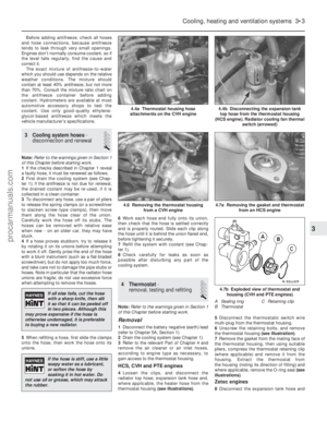 98
98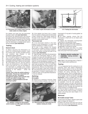 99
99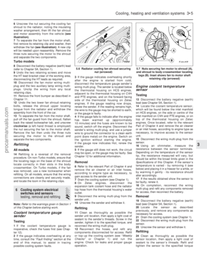 100
100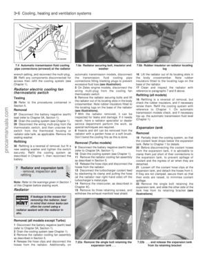 101
101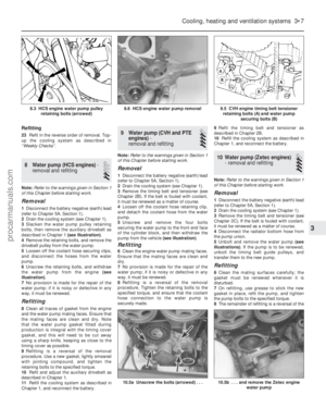 102
102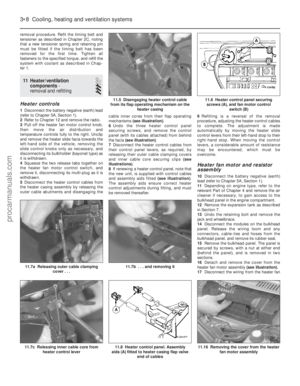 103
103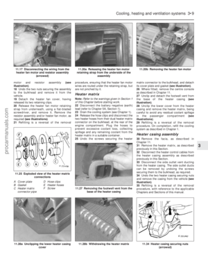 104
104 105
105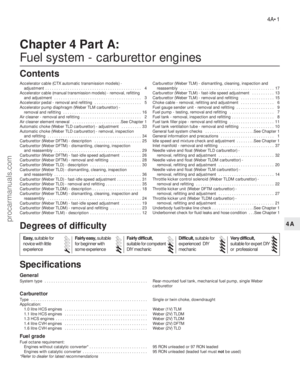 106
106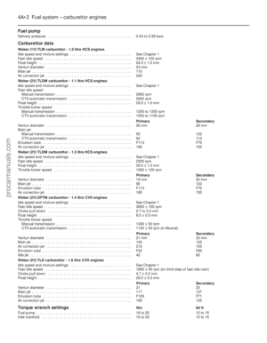 107
107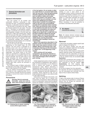 108
108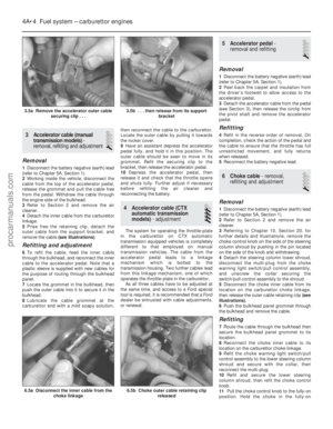 109
109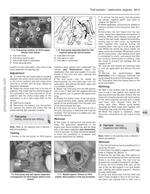 110
110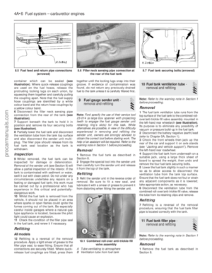 111
111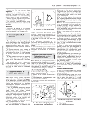 112
112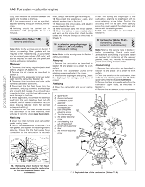 113
113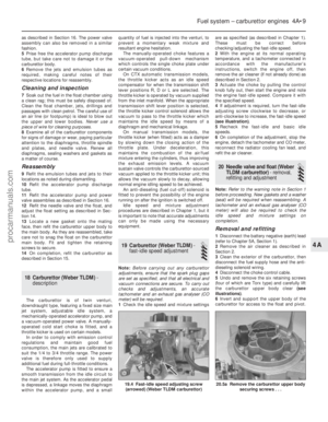 114
114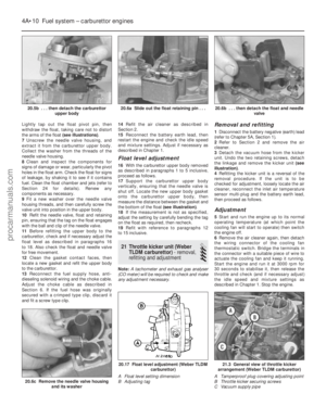 115
115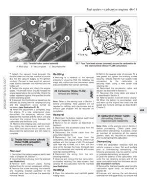 116
116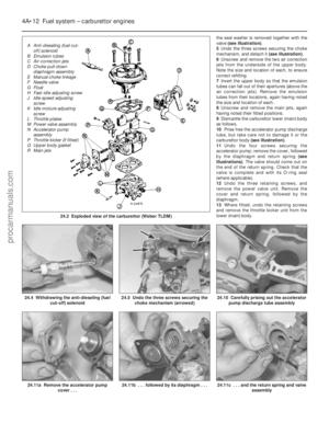 117
117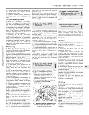 118
118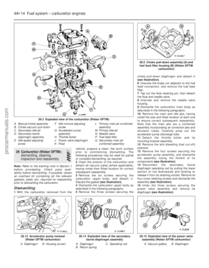 119
119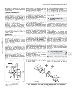 120
120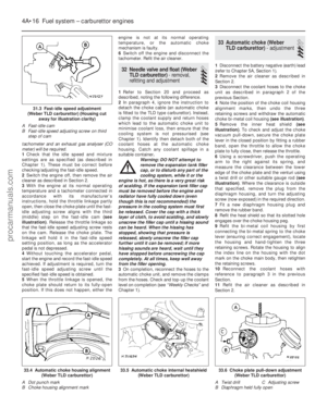 121
121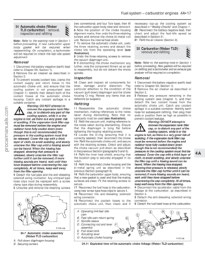 122
122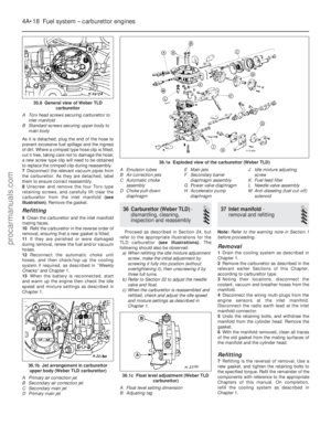 123
123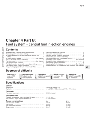 124
124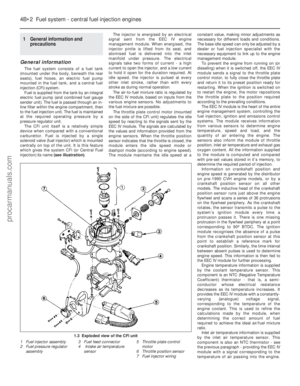 125
125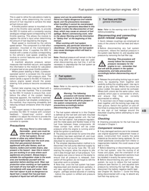 126
126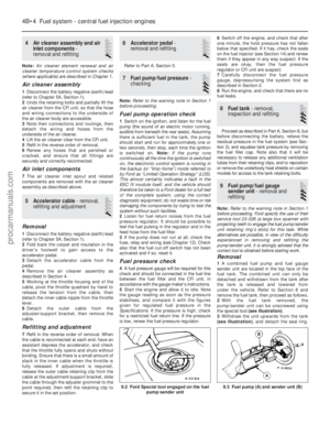 127
127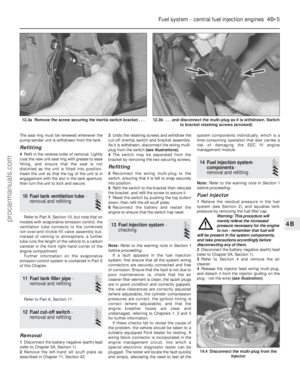 128
128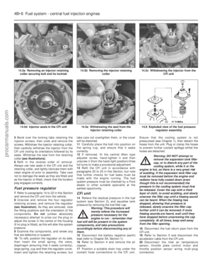 129
129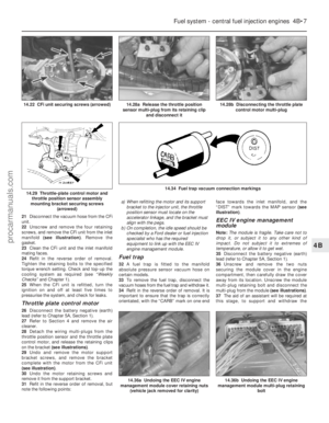 130
130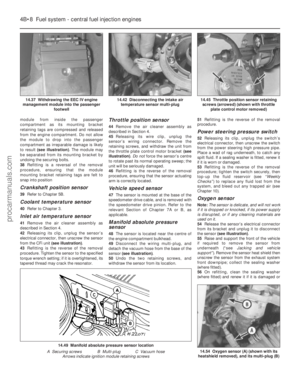 131
131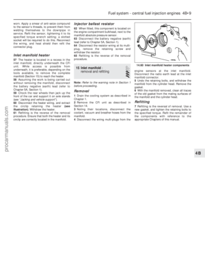 132
132 133
133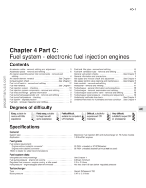 134
134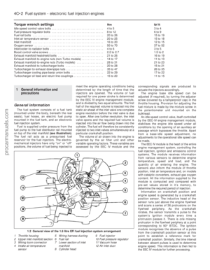 135
135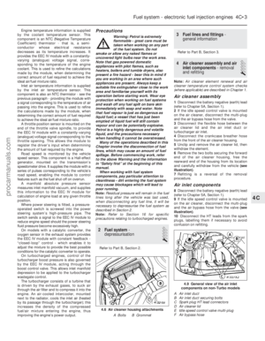 136
136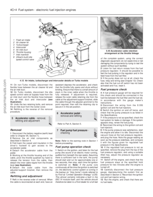 137
137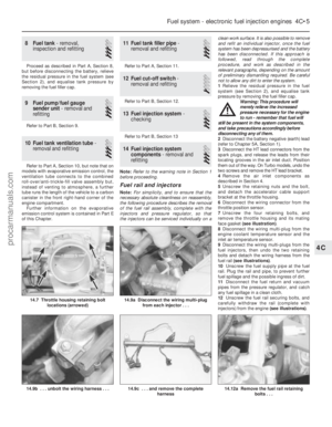 138
138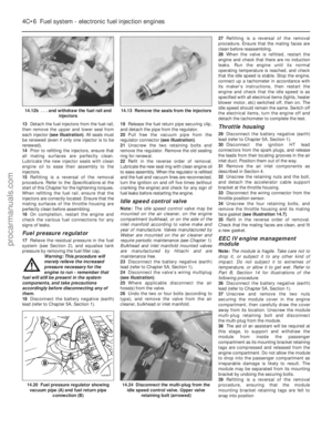 139
139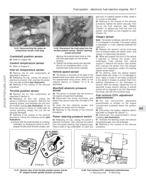 140
140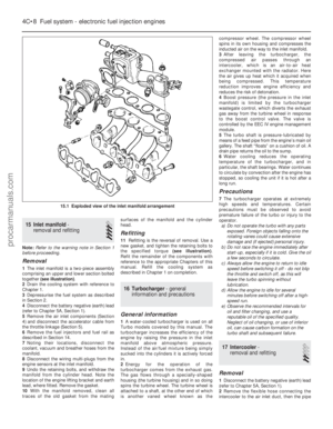 141
141 142
142 143
143 144
144 145
145 146
146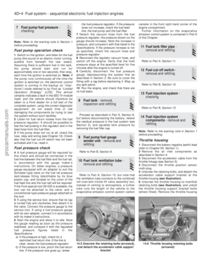 147
147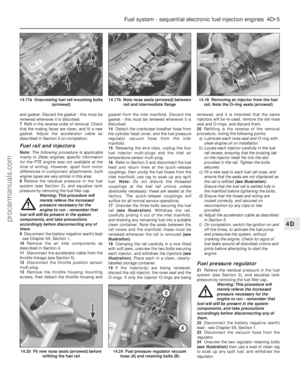 148
148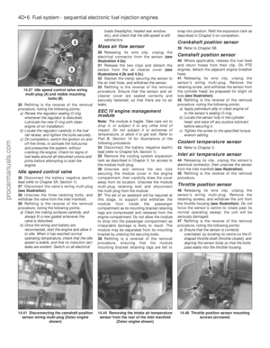 149
149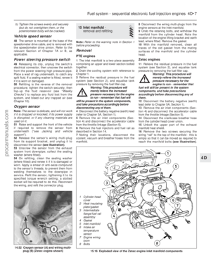 150
150 151
151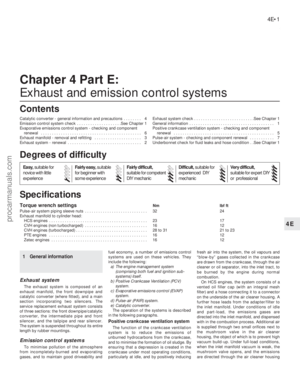 152
152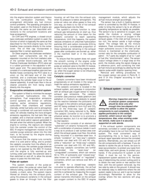 153
153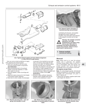 154
154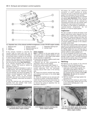 155
155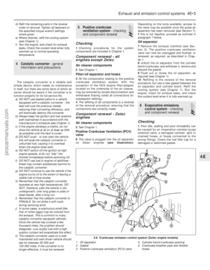 156
156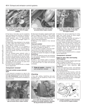 157
157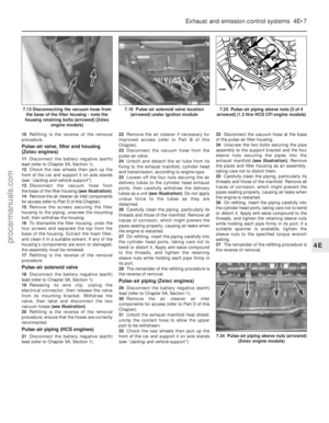 158
158 159
159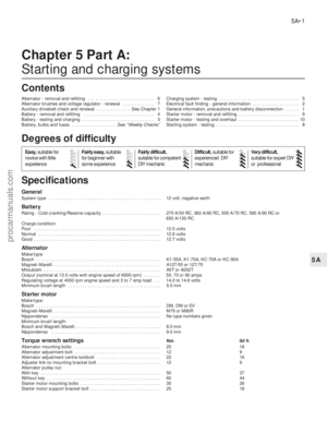 160
160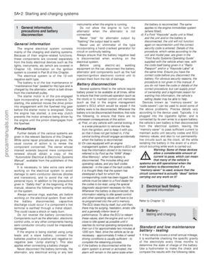 161
161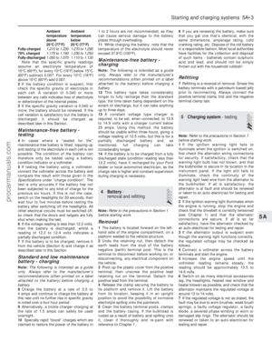 162
162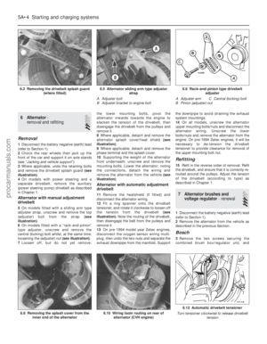 163
163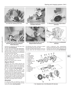 164
164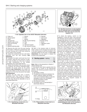 165
165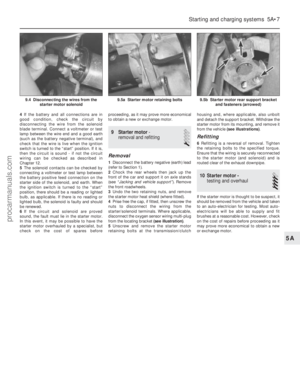 166
166 167
167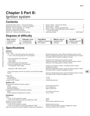 168
168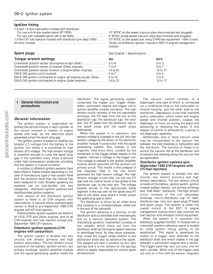 169
169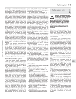 170
170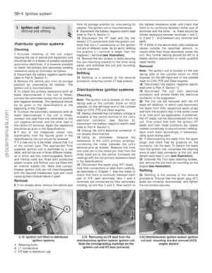 171
171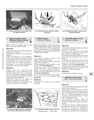 172
172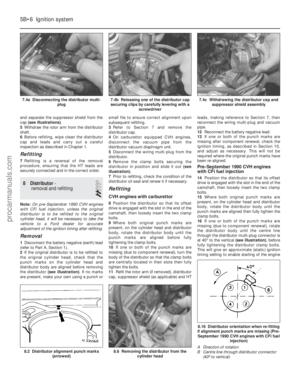 173
173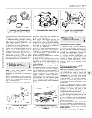 174
174 175
175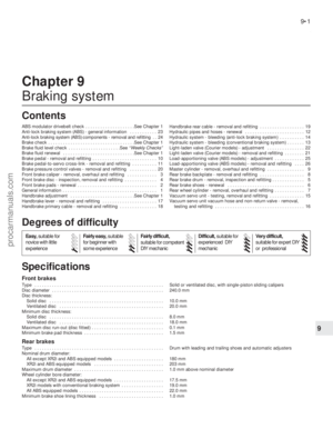 176
176 177
177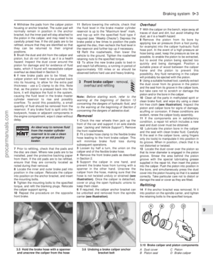 178
178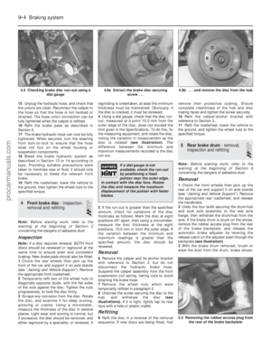 179
179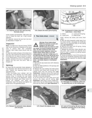 180
180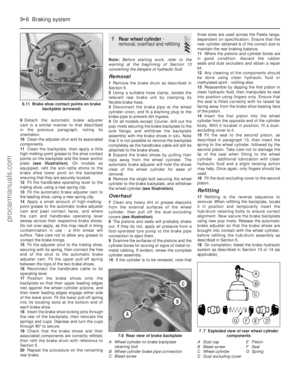 181
181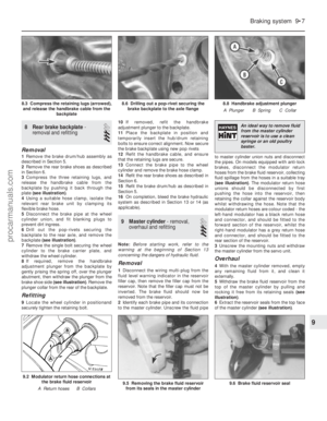 182
182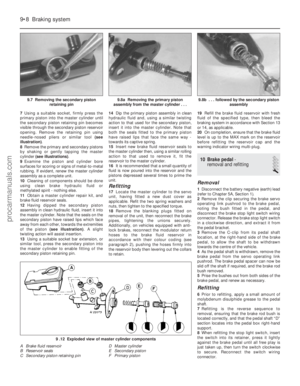 183
183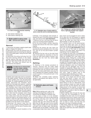 184
184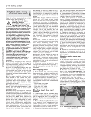 185
185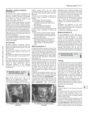 186
186 187
187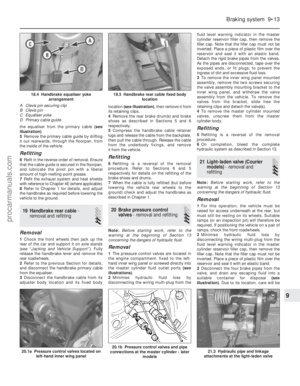 188
188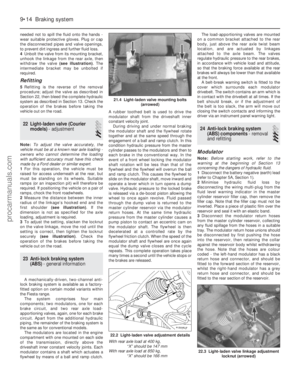 189
189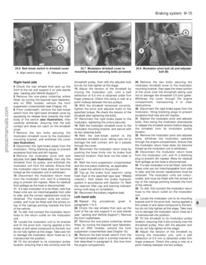 190
190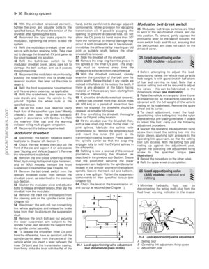 191
191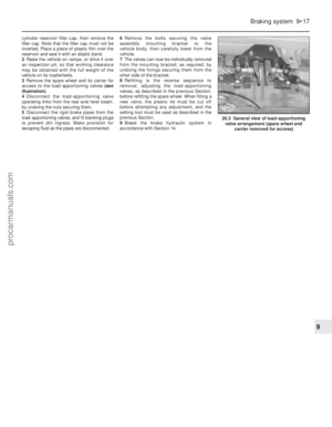 192
192 193
193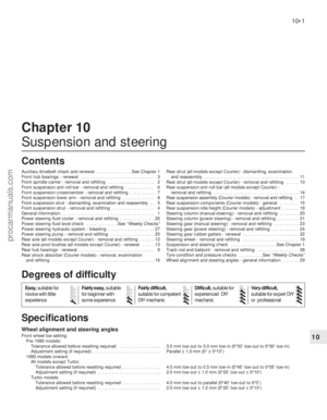 194
194 195
195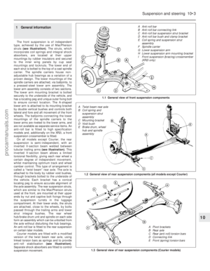 196
196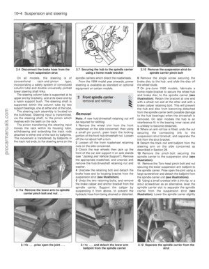 197
197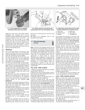 198
198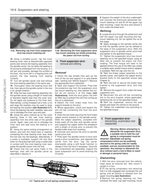 199
199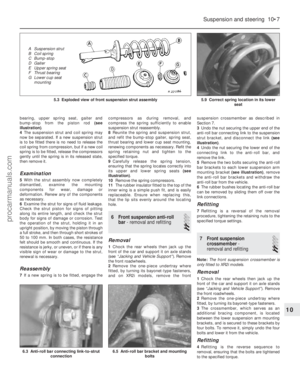 200
200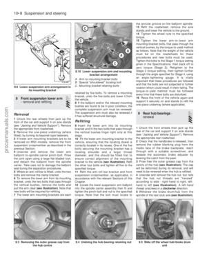 201
201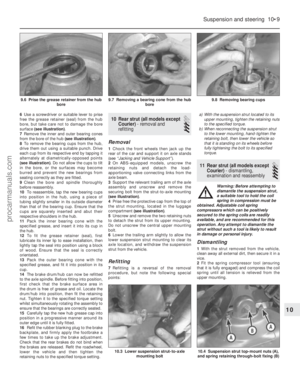 202
202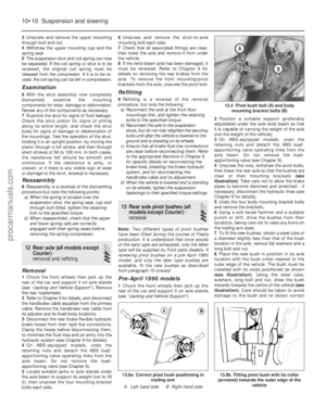 203
203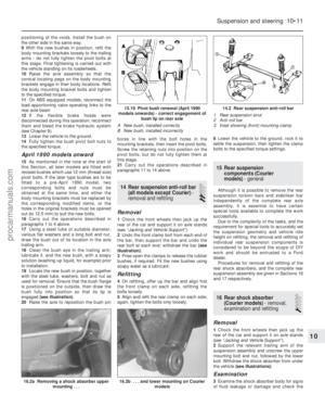 204
204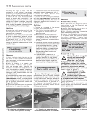 205
205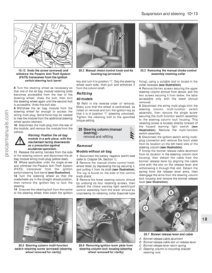 206
206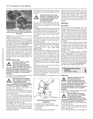 207
207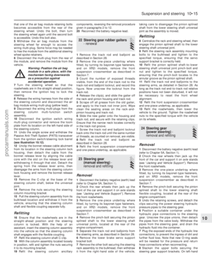 208
208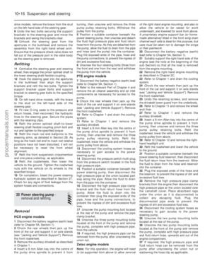 209
209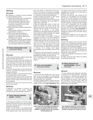 210
210 211
211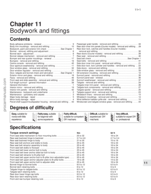 212
212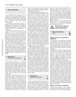 213
213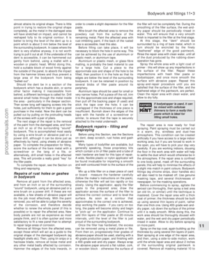 214
214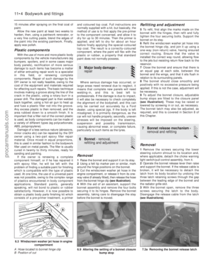 215
215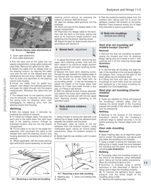 216
216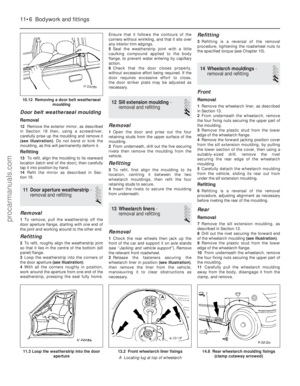 217
217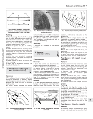 218
218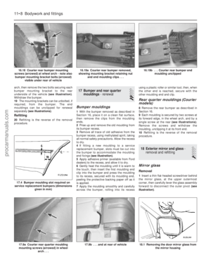 219
219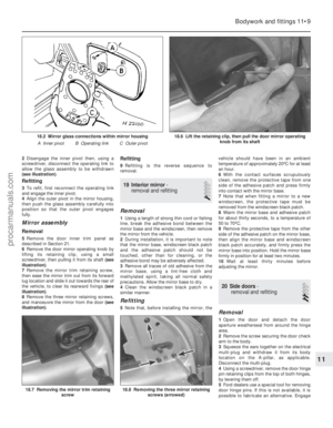 220
220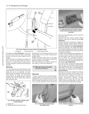 221
221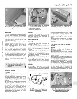 222
222 223
223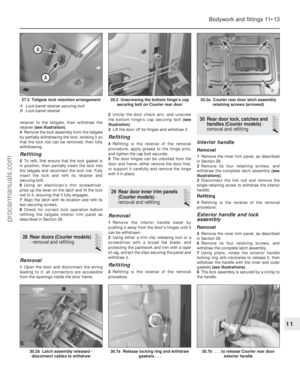 224
224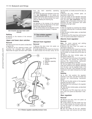 225
225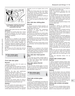 226
226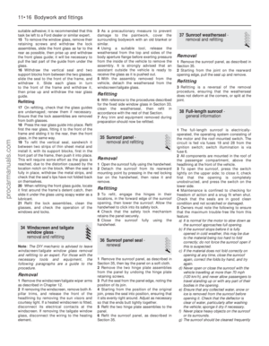 227
227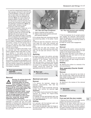 228
228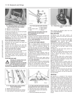 229
229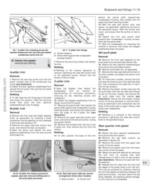 230
230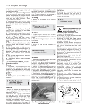 231
231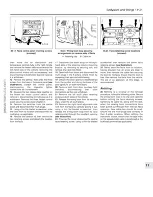 232
232 233
233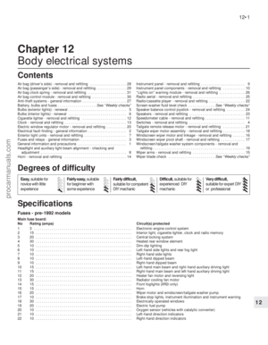 234
234 235
235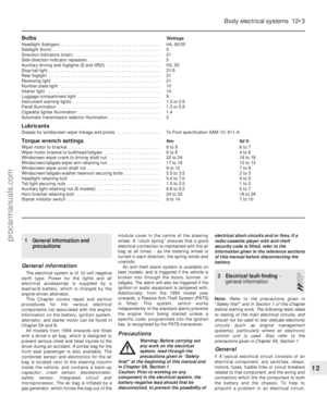 236
236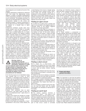 237
237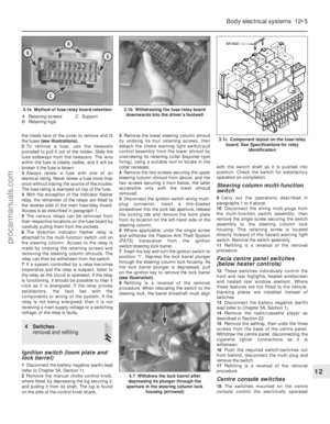 238
238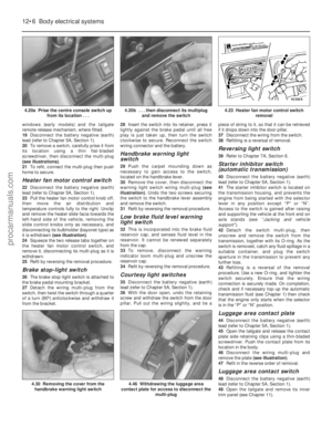 239
239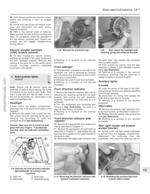 240
240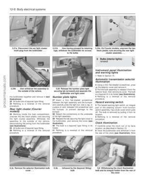 241
241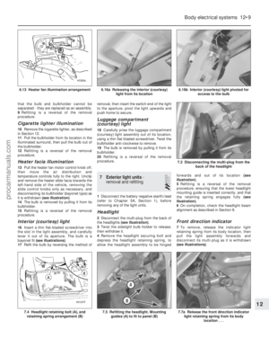 242
242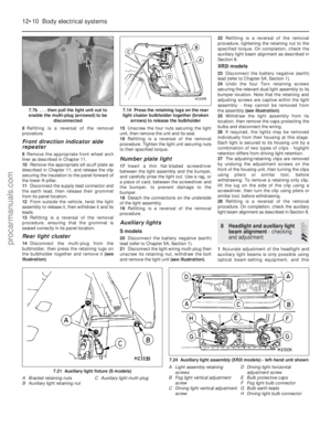 243
243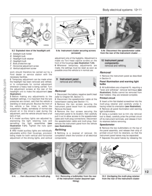 244
244 245
245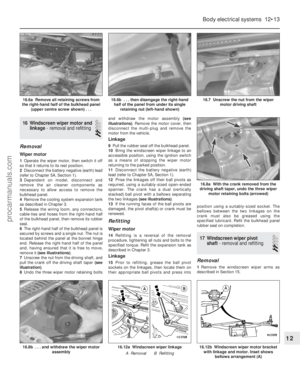 246
246 247
247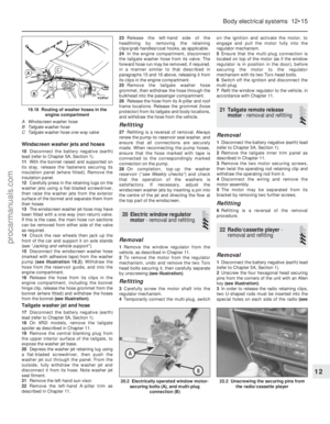 248
248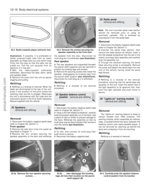 249
249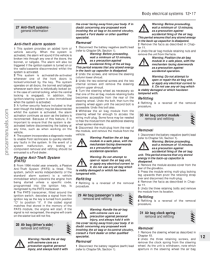 250
250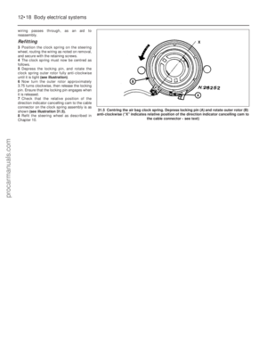 251
251 252
252 253
253 254
254 255
255 256
256 257
257 258
258 259
259 260
260 261
261 262
262 263
263 264
264 265
265 266
266 267
267 268
268 269
269 270
270 271
271 272
272 273
273 274
274 275
275 276
276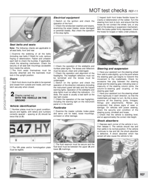 277
277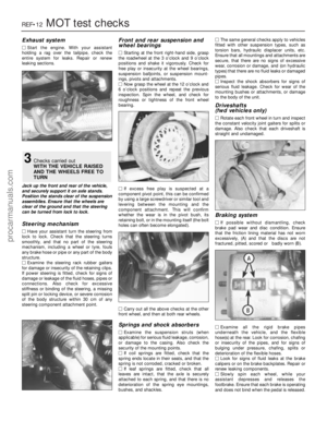 278
278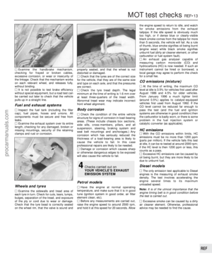 279
279 280
280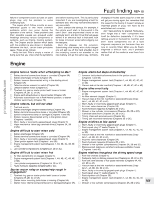 281
281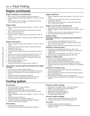 282
282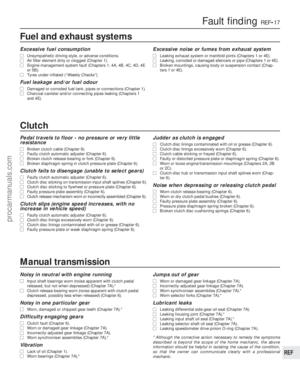 283
283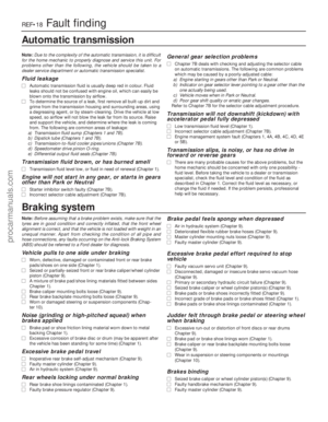 284
284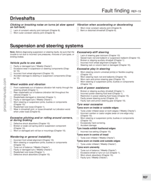 285
285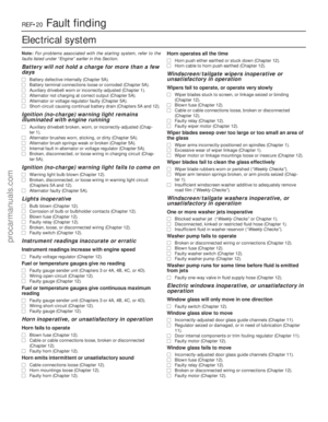 286
286 287
287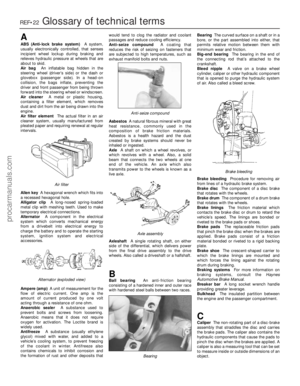 288
288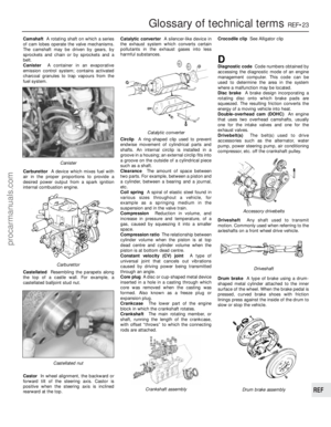 289
289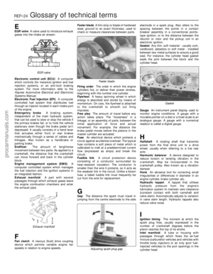 290
290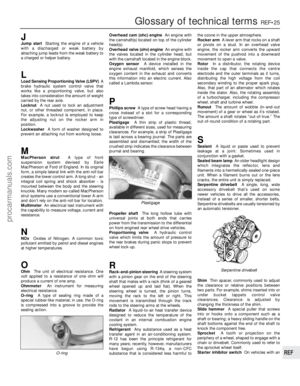 291
291 292
292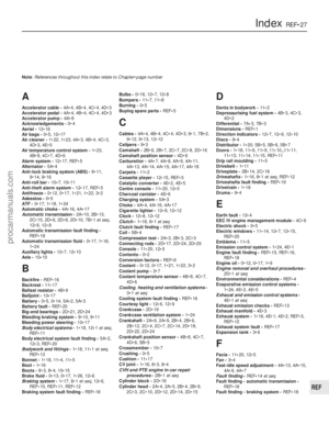 293
293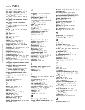 294
294 295
295