Page 225 of 296

Refitting
9Refitting is the reverse of the removal
procedure.
Upper and lower door catches
Removal
10 Remove the inner trim panel, as described
in Section 29.
11 Remove its four retaining screws, and
withdraw the complete latch assembly.
Disconnect the upper and lower catch cables from the latch assembly operating
mechanism.
12
Unbolt the catch and withdraw it from the
door (see illustration) . If the cables are
available separately (seek the advice of a Ford
dealer) they can be disconnected from each
catch by releasing the retaining clip.
Refitting
13 Refitting is the reverse of the removal
procedure; check the adjustment of the catch
before finally tightening the bolts.
14 The striker plates can be adjusted on their
slotted mounting bolt locations, if required.
31 Door window regulator -
removal and refitting
3
Manual front regulator
Removal
1 Remove the door inner trim panel, as
described in Section 21.
2 Locally detach the PVC sheet from the door
to allow access into the door cavity. Do not tear the sheet; cut closely around the clips, as
required.
3
Remove the door window glass, as
described in Section 32.
4 Drill the heads off the regulator securing
rivets and manoeuvre the regulator assembly
from the door (see illustration) . Lay the
regulator body in the bottom of the door, then
withdraw the gear mechanism and cable
followed by the rigid “pillar”.
Refitting
5 Refit the regulator by reversing the method
of removal, ensuring that it is securely riveted
to the door.
6 Refit the door window glass, as described
in Section 32.
7 Re-secure the PVC sheet then refit the door
inner trim panel as described in Section 21.
Electric front regulator
Removal
Note : For motor removal and refitting
procedure, refer to Chapter 12.
8 Remove the door inner trim panel, as
described in Section 21.
9 Locally detach the PVC sheet from the door
to allow access into the door cavity. Do not
tear the sheet; cut closely around the clips, as
required.
10 Remove the door window glass, as
described in Section 32.
11 Disconnect the multi-plug on the regulator
motor body, and remove the three nuts
securing the motor/winding mechanism
section of the assembly to the door.
12 Drill the heads off the regulator securing
rivets and manoeuvre the regulator assembly
from the door. Lay the regulator body in the
bottom of the door, then withdraw the gear
mechanism and cable followed by the rigid
“pillar”.
Refitting
13 To refit, first position the regulator
assembly in the door, and refit the three nuts
securing the motor/winding mechanism
section.
14 Re-rivet the pillar section of the regulator
assembly securely to door.
15 Reconnect the multi-plug to the regulator
motor body.
16 Refit the door window glass, as described
in Section 32.
17 Re-secure the PVC sheet then refit the
door inner trim panel as described in Sec-
tion 21.
Rear regulator
Removal
18 Remove the door inner trim panel, as
described in Section 21.
19 Locally detach the PVC sheet from the
door to allow access into the door cavity. Do
not tear the sheet; cut closely around the
clips, as required.
20 Drill the heads off the four regulator
securing rivets, and remove the two lower
11•14 Bodywork and fittings
31.4 Window regulator assembly (manual, front)
30.12 Courier rear door lower catch
removal
1595Ford Fiesta RemakeA Window glass lifting
channel
B Regulator assembly
C Rivets
D Screwsprocarmanuals.com
http://vnx.su
Page 226 of 296
 .
21 Support the window glass then, having
pushed the regulator into the door cavity,
disconnect the regulator arm from it. Remove
the regulator a")
window glass guide securing screws (see
illustration) .
21 Support the window glass then, having
pushed the regulator into the door cavity,
disconnect the regulator arm from it. Remove
the regulator assembly.
Refitting
22 Refitting is a reversal of the removal
procedure, ensuring that the window regulator
is securely riveted to the door. Check the
operation of the window regulator, by
temporarily refitting the regulator handle and,
if necessary, adjust the window glass guide to
ensure that the window glass does not stick
or judder.
23 Re-secure the PVC sheet then refit the
door inner trim panel as described in Sec-
tion 21.
32 Door window glass -
removal and refitting
3
Front side door glass
Removal
1 Remove the door inner trim panel, as
described in Section 21.
2 Locally detach the PVC sheet from the door
to allow access into the door cavity. Do not
tear the sheet; cut closely around the clips, as
required.
3 Remove the door belt weatherseal
moulding as described in Section 10.
4 Remove the two screws securing the
window glass lifting channel to the regulator
assembly, through either their upper or lower
access holes. Support the glass as the screws
are removed.
5 Remove the window glass by tilting it
forwards towards the hinge end of the door,
then withdraw it towards the latch end.
Refitting
6 To refit, position the window glass into the
door by reversing the method of removal.
7 Loosely refit the two screws to hold the
window glass lifting channel to the regulator assembly, but do not tighten them at this
stage.
8
Raise the window glass fully, then tighten
the retaining screws through their upper
access holes. This ensures correct positioning
of the window glass in its aperture.
9 Refit the door belt weatherseal moulding as
described in Section 10.
10 Re-secure the PVC sheet then refit the
door inner trim panel as described in Sec-
tion 21.
Rear side door sliding glass
Removal
11 Remove the door window regulator, as
described in Section 31, then fully lower the
window glass into the door.
12 Remove the door belt weatherseal
mouldings in a similar manner to that
described in Section 10.
13 Remove the remaining two window glass
guide securing screws from their location at
the top of the door, and disengage the top
of the guide.
14 Manoeuvre the fixed rear quarter window
glass forwards and out from its location, along
with the window glass guide. Lift out the
plastic strip.
15 Manoeuvre the door window glass up and
out of the door, from the exterior side of the
door.
Refitting
16 Refitting is a reversal of the removal
procedure, ensuring that the fixed rear quarter
window seats correctly in its location, and that
the window glass guide holds the window
glass correctly (refer to Section 31).
Rear side door fixed quarter
glass
17 The fixed rear quarter window glass is
removed and refitted in conjunction with the
rear side door sliding glass described
previously in this Section.
Rear door glass (Courier
models)
18 The rear door window glass on Courier
models is removed and refitted using the
same technique as for the fixed side window
glass described in Section 33.
33 Side window glass -
removal and refitting
3
Fixed side window glass
Removal
1 The lip of the weatherseal surrounding the
window glass must be released from the top
and sides of the body aperture flange, using a
suitable tool, before exerting pressure from
the inside of the vehicle to remove the glass.
Any surrounding interior trim should be
removed. It is important that an assistant helps and holds the glass from the outside as
it is pressed out from the inside.
2
With the assembly removed from the
vehicle, detach the weatherseal from the
window glass.
3 If the weatherseal is to be re-used it should
be cleaned. Do not use petrol, white spirit or
other similar substances, as they may cause
rapid rubber deterioration. Ensure that the
glass groove in the weatherseal is free from
any sealant or glass fragments.
4 Ensure that the body aperture flange is free
from any sealant also.
Refitting
5 Commence refitting by attaching the
weatherseal to the window glass, ensuring
that it is seated correctly.
6 Insert a length of nylon or terylene cord into
the body aperture flange groove of the
weatherseal, so that the cord ends emerge at
the top centre of the window, and overlap by
approximately 150.0 mm.
7 Offer the assembly to the body aperture,
and engage the lower lips of the weatherseal
over the body aperture flange. Ensure that the
engagement of the weatherseal lips is not
hampered in any way, and that the cord ends
are protruding inside the vehicle.
8 With an assistant applying a gentle even
pressure on the window glass from the
outside, pull one end of the cord at right-
angles to the glass. This will pull the inner lip
of the weatherseal over the body aperture
flange.
9 When the cord has been pulled halfway
around the aperture, repeat the procedure
with the other end of the cord. The cord
should release when the window glass is fully
fitted.
10 Refit any disturbed interior trim as
necessary.
Hinged side window glass
Removal
11 With an assistant standing outside ready
to take the window, unscrew the single screw
securing each hinge, then open the window
and unscrew the two screws securing the
catch to the body. Withdraw the window.
12 The weatherstrip can now be removed
and refitted, if required.
Refitting
13 To refit the window, have your assistant
stand outside and offer up the window so that
both hinge leaves enter their sockets, then
loosely refit the catch securing screws. Refit
the hinge securing screws, then adjust the
catch position to ensure that the window is
clamped evenly on to the weatherstrip over
the whole mating surface when the catch is
fastened. Tighten all screws securely.
Sliding side window and glass
Removal
14 To remove the complete sliding window
assembly on Courier Kombi models requires
special cutting equipment and supplies of
Bodywork and fittings 11•15
31.20 Regulator retaining rivets (A) and lower window glass guide securing screws (B) on rear door
11
1595Ford Fiesta Remakeprocarmanuals.com
http://vnx.su
Page 227 of 296

suitable adhesive; it is recommended that this
task be left to a Ford dealer or similar expert.
15To remove the window glass, remove their
retaining screws and withdraw the lock
assemblies, slide the front glass as far to the
rear as possible, then prise up and withdraw
the front glass guide; it will be necessary to
pull the last part of the guide from under the
glass.
16 Withdraw the vertical seal and two
support blocks from between the two glasses,
slide the seal to the front of the frame, and
withdraw it. Slide each glass in turn
to the front of the frame and withdraw it,
then prise up and withdraw the rear glass
guide.
Refitting
17 On refitting, check that the glass guides
are undamaged; renew them if necessary.
Ensure that the lock assemblies are removed
from both glasses.
18 Press the rear glass guide into place. Refit
first the rear glass, fitting it to the front of the
frame and sliding it to the rear, then the front
glass, in the same way.
19 To refit the vertical seal, sandwich it
between two strips of thin sheet metal and
install it, with its support blocks, first in the
front part of the frame, then push it into place.
This will require some effort as the glass is
reached, due to the distortion caused by the
location notch on the block. When the seal is
fully in place, withdraw the metal strips, and
check that the seal’s lips have not folded back
on themselves.
20 When refitting the front glass guide, locate
it first around the frame’s detent catch, then
slide it under the glass using soapy water as a
lubricant.
21 Refit the lock assemblies, clean the
glasses, and check the operation of the
windows and locks.
34 Windscreen and tailgate window glass -
removal and refitting
4
Note : The DIY mechanic is advised to leave
windscreen/tailgate window glass removal
and refitting to an expert. For those with the
necessary tools and equipment, the
following paragraphs are a guide to the
procedure.
Removal
1 Remove the windscreen/tailgate wiper arms
as described in Chapter 12.
2 If removing the windscreen, remove both A-
pillar trims, and release the front of the
headlining by removing the sun visors and
courtesy light. If a heated windscreen is fitted,
disconnect its electrical contacts at the
windscreen. If removing the tailgate window
glass, disconnect the wiring to the heating
element. 3
As a precautionary measure to prevent
damage to the paintwork, cover the
surrounding bodywork with an old blanket or
similar.
4 Using a suitable tool, release the
weatherseal from the top and sides of the
body aperture flange before exerting pressure
from the inside of the vehicle to remove the
assembly. It is strongly advised that an
assistant outside the vehicle is ready to
receive the glass as it is pushed out.
5 With the assembly removed from the
vehicle, detach the weatherseal from the
windscreen/tailgate glass.
Refitting
6 With reference to the procedures described
for the fixed side window glass in Section 33,
clean the weatherseal, then refit in
accordance with the rest of that Section.
7 Any trim and equipment removed during
preparation should now be refitted.
35 Sunroof panel -
removal and refitting
1
Removal
1 Open the sunroof fully using the handwheel.
2 Detach the sunroof from its rearward
mounting point by pressing in the red locking
bar on the handwheel, then raise it and
remove.
Refitting
3 To refit, engage the hinges in their
locations, in the forward edge of the sunroof
opening, then lower the sunroof. Allow the
handwheel to click into its safety lock.
4 Check that the safety lock mechanism
retains the panel securely.
5 Close the sunroof fully using the
handwheel.
36 Sunroof panel seal -
renewal
1
1 Remove the sunroof panel, as described in
Section 35, then lay the panel on a soft cloth.
2 Remove the two hinge plate assemblies
from the panel by undoing the hinge plate
retaining screws.
3 Pull the seal from the panel edge, noting the
position of its join.
4 Starting from the position of the original
join, press the seal into position, ensuring that
it sits evenly right around. Adjust as necessary
so that the ends butt tightly together.
5 Refit the two hinge plate assemblies to the
panel.
6 Refit the sunroof panel, as described in
Section 35.
37 Sunroof weatherseal -
removal and refitting
1
Removal
1 Remove the sunroof panel, as described in
Section 35.
2 Starting from the joint on the rearward
opening edge, pull the seal up and remove.
Refitting
3 Refitting is a reversal of the removal
procedure, ensuring that the weatherseal
does not deform at the corners, or split at the
joint.
38 Full-length sunroof -
general information
1 The full-length sunroof is electrically-
operated, the operating system consisting of
the motor and the roof-mounted switch. The
circuit is fed via fuses 18 and 28 from the
ignition switch; switch illumination is via
fuse 6.
2 All components are mounted in the roof of
the passenger compartment, above the
headlining at the front of the vehicle.
3 To open the sunroof, press the switch
lightly on the upper side; to close it, check
first that the opening is completely
unobstructed, and press the switch on the
lower side.
4 Maintenance is confined to checking for
freedom of action and a snug fit when shut.
Check that the seals are in good clean
condition and not scratched or damaged.
5 Owners must note the following to ensure
that the maximum trouble-free life from this
feature:
a) It is normal for the motor to slow down as
the sunroof approaches full opening.
b) If the sunroof stops before it is fully
opened in cold weather, this may be due
to the material being too hard to fold
correctly; do not force the sunroof open if
this is suspected.
c) If the material does not fold correctly on
opening at any time, close the sunroof
again, correct the folds by hand, and try
again.
d) Never open or close the sunroof with the
vehicle travelling at more than 70 mph
(120 km/h), and never allow passengers to
travel standing up or with any part of their
bodies in the opening.
e) Ensure that any collected water, snow or ice is removed from the sunroof before
opening it. Check that the deflector is
clear of water, particularly after washing
the vehicle; sponge it dry if necessary.
f) Never place heavy objects on the sunroof or its surrounds.
g) The sunroof should be cleaned frequently
11•16 Bodywork and fittings
1595Ford Fiesta Remakeprocarmanuals.com
http://vnx.su
Page 228 of 296

to avoid the material being stained by dirt.
Use a sponge, soft brush or soft cloth and
a neutral detergent, rinsing with a gentle
flow of clean water from directly above
until all traces of dirt and detergent are
removed. Neveruse a high-pressure jet,
pressure washer or similar, and do not
aim the jet from a hose at the joints of the
sunroof with the body (or water will enter
the passenger compartment). Neveruse
alcohol, petrol, thinners or similar
products to clean the material.
h) If the vehicle is parked in heavy rain, or if it is parked outside for long periods, a
proprietary car cover or tarpaulin should
be used to protect the roof and body. Do
not leave the sunroof open for long
periods; the material will stiffen in its folds,
with a consequent risk of tearing when the
sunroof is eventually operated again.
6 If the system fails with the sunroof open, it
can be closed in emergency by switching off
the ignition, prising out the access plug in
front of the switch, and using the crank
provided to rotate the motor shaft clockwise
until the roof is closed.
7 If the switch is thought to be at fault, it can
be removed after first disconnecting the
battery negative (earth) lead (refer to Chap-
ter 5, Section 1) ; the switch can then be
eased from its housing until the wires can be
disconnected. Refitting is the reverse of the
removal procedure.
8 If any other failure or problem is
encountered, the general inaccessibility of the
system’s components means that servicing
and fault-finding is beyond the capabilities of
most owners; the vehicle should be taken to a
Ford dealer for attention.
39 Front seat and slide assembly -
removal and refitting
1
Removal
Warning: On vehicles fitted with
mechanical seat belt pre-
tensioning stalks, be careful
when handling the seat, as the
tensioning device (“grabber”) contains a
powerful spring, which could cause injury
if released in an uncontrolled fashion. The
tensioning mechanism should be
immobilised by inserting a safety “transit
clip” available from Ford parts stockists.
You are strongly advised to seek the
advice of a Ford dealer as to the correct
use of the “transit clip” and the safety
implications before proceeding.
1 On pre-1994 models, slide the seat fully
rearwards to expose the two front slide
assembly to floorpan bolts. Remove all four
bolts securing the slides to the floorpan, and
remove the seat from the vehicle.
2 On later models, pull off the trim cover from
the outer slide. 3
On vehicles fitted with mechanical seat belt
pre-tensioning stalks, fit the safety “transit
clip”.
4 Slide the seat fully rearwards, remove the
inner slide trim cover then unscrew and
remove the front slide assembly to floorpan
bolts.
5 Now slide the seat fully forward, and
unscrew the rear slide securing bolts each
side. Lift the seat and remove it from the
vehicle.
Refitting
6 Position the seat in the vehicle, and align
the slide assemblies with their mounting bolt
locations in the floorpan. Refit the front
securing bolts first, followed by the
rear securing bolts, to ensure that the seat
runs smoothly in its slide mechanism. Tighten
the bolts to the specified torque. On later
models, remove the “transit clip” (where
applicable) and refit the trim covers.
40 Rear seat -
removal and refitting
1
Backrest and catch
Removal
1 To remove the backrest, release the
backrest catch/catches, then fold the
backrest forwards.
2 Remove the hinge-to-backrest securing
screws, then remove the backrest (see
illustration) .
3 The hinges may be removed at this stage if
required, by undoing the hinge-to-body
securing screws.
4 If desired, the rear seat backrest catch may
be removed by removing the catch retaining
bolts (see illustration) .
Refitting
5If removed, refit the backrest catch and
secure with the retaining bolts.
6 To install the backrest, align the hinges to
the body and backrest, then loosely refit the
securing screws. 7
Fold the backrest into its upright position
and engage the backrest catch/catches.
Adjust the alignment of the components then,
when correct, tighten the securing screws to
their specified torques.
8 Check for correct catch engagement.
Cushion
Removal
9To remove the cushion, remove the three
screws securing the forward edge of the seat
cushion to the raised floorpan section.
10 Push down and back on the cushion, to
disengage the hook and catch on the rear
underside of the seat.
11 Remove the seat from the vehicle after
guiding the seat belt clips through the slits in
the seat cushion.
Refitting
12 Refitting the cushion is a reversal of the
removal procedure.
Seat assembly (Courier Kombi
models)
Removal
13 The seats are secured by two bolts at
each forward hinge, visible once the seat has
been folded forwards. Unbolt the hinges and
withdraw the seat assembly.
Refitting
14 Refitting is the reverse of the removal
procedure.
41 Seat belts -
removal and refitting
3
Removal
Front seat belt (five-door models)
1 Remove the cover from the upper anchor
position and remove the anchor bolt.
2 Remove the lower anchor bolt from its
location on the floor by the base of the B-
pillar. Prevent the retractor unit from reeling in
too great a quantity of seat belt by attaching a
clothes peg, or similar item, to the seat belt.
Bodywork and fittings 11•17
40.4 Rear seat backrest catch retaining bolts (arrowed)40.2 Rear seat hinge arrangement
A Hinge-to-backrest screw locations
B Hinge-to-body screw locations (removed after backrest detached)
11
1595Ford Fiesta Remakeprocarmanuals.com
http://vnx.su
Page 229 of 296

securing the seat belt retractor unit to its
location in the base of the B-pill")
3Remove the B-pillar trim and sill scuff plate
as described in Section 42.
4 Remove the bolt (two bolts on later models)
securing the seat belt retractor unit to its
location in the base of the B-pillar (see
illustration) , then remove the retractor unit
and the seat belt from the vehicle.
Front seat belt (three-door models)
5 Remove the rear quarter trim panel, as
described in Section 42.
6 Undo the bolt securing the seat belt
retractor unit to its location, then remove the
retractor unit and seat belt from the vehicle.
Front seat belt (Van models)
7 Remove the cover from the upper anchor
position and remove the anchor bolt.
8 Undo the bolt securing the retractor unit
and integral lower anchor position, then
remove the retractor unit and seat belt from
the vehicle.
Front seat belt stalk
Warning: On vehicles fitted with
mechanical seat belt pre-
tensioners, any work on the seat
belt stalk should be entrusted to
a Ford dealer. The following procedure is
therefore only applicable to models with conventional seat belt stalks which DO
NOT incorporate any form of pre-
tensioning device.
9
Remove the bolt securing the seat belt stalk
assembly to the floor, between the two front
seats, noting the arrangement of washers and
spacers (see illustration) . Remove the stalk
assembly from the vehicle.
Front seat belt height adjuster
Note : If a height adjuster mechanism is not
fitted, it is possible to lower the upper anchor
position from its production setting, by
removing the plug from the lower adjuster
plate hole and bolting the anchor into this (see
illustration 41.13) . The plug can then be fitted
to the production setting hole.
10 Remove the height adjuster knob by
carefully inserting a small screwdriver into the
aperture on the underside of the knob, and
gently levering it off.
11 Remove the anchor cover, again using a
screwdriver, then remove the anchor bolt and
anchor (see illustration) .
12 Remove the door aperture weatherseal(s)
around the B-pillar location, then remove the
B-pillar trim, as described in Section 42.
13 Remove the bolts securing the adjuster
plate to the B-pillar, noting washer fitment, then remove the adjuster plate from the
vehicle
(see illustration) .
Rear seat belts
14Remove the rear seat cushion, as
described in Section 40, then also remove the
parcel shelf.
15 Undo the bolt securing each seat belt
buckle assembly to its body location (see
illustration) , and remove the buckle
assemblies from the vehicle, as required.
16 Prevent the retractor units from reeling in
too much seat belt by attaching a clothes peg
or similar item to the belt, close to the
retractor unit.
17 Detach the seat belt lower anchor by
removing its retaining bolt.
18 Remove the upper anchor bolt cover and
undo the bolt securing the anchor to its
location. Detach the anchor, noting any
spacer fitment.
19 On vehicles fitted with a parcel shelf,
remove the seat belt guide from the parcel
shelf support/rear loudspeaker housing, then
pass the seat belt through it.
20 On vehicles without a parcel shelf as
standard, remove the trim panel covering the
seat belt retractor unit, where fitted, by
undoing its retaining screws. Remove the seat
belt guide from the trim panel, then pass the
seat belt through it.
21 Remove the bolt securing the seat belt
retractor unit to its body location, then
withdraw the retractor unit and the seat belt
from the vehicle.
Refitting
22 Refitting is a reversal of the removal
procedure, noting the following points. Ensure
that the tag on the retractor unit engages in its
body location and, in the case of the rear seat
belts, that it does not trap the wiring loom
between itself and the body. Having fitted the
upper anchor to its location, ensure that it can
rotate freely. The stalk assembly anchor(s)
must engage to the anti-rotation floorpin(s)
and, when refitting a rear centre lap
belt/buckle assembly, the lap belt must be
fitted to lie on the right-hand side of the
vehicle. Tighten all bolts to their specified
torque.
11•18 Bodywork and fittings
41.15 Rear seat belt and buckle securing
arrangements (rear seat cushion removed)
A Seat belt lower anchor retaining bolts
B Centre lap belt/single buckle assembly securing bolt
C Dual buckle assembly securing bolt41.13 Seat belt upper anchor position (fixed and adjustable)
A Adjuster plate securing bolt
B Anchor bolt position (production setting)
C Lower setting for fixed type (if required)
41.11 Removing a seat belt upper anchor cover41.9 Front seat belt stalk assembly
A Bolt
B Anti-rotation plate
C Stalk D Metal washers
E Paper washer
F Floorpin
41.4 Seat belt retractor unit location in
base of B-pillar (five-door models)
A Retractor unit locating tag
B Retractor unit securing bolt
1595Ford Fiesta Remakeprocarmanuals.com
http://vnx.su
Page 230 of 296
 .
2 Detach the do")
42 Interior trim panels-
removal and refitting
2
A-pillar trim
Removal
1 Remove the securing screw from the trim
panel, located near to the windscreen top
corner (see illustration) .
2 Detach the door aperture weatherseal from
around the trim panel, then pull the trim panel
from the pillar.
Refitting
3 To refit, align the trim fixing lugs to the pillar
and press into position. Refit the securing
screw then push the door aperture
weatherseal back onto its flange.
B-pillar trim
Removal
4 Remove the front seat belt height adjuster
knob, as applicable, by inserting a small
screwdriver into the aperture on the underside
of the knob and levering it off.
5 Remove the upper seat belt anchor bolt
cover, and remove the bolt, as required.
6 Open the doors and detach the door
aperture weatherstrip from the area around
the B-pillar trim. 7
Remove the securing screws and detach
the trim.
Refitting
8 Refitting is the reverse sequence to
removal, tightening the seat belt anchor bolt
to the specified torque. Ensure that the
anchor is free to rotate.
C-pillar trim
Removal
9 Open the tailgate, then detach the
loudspeaker from its location by
disconnecting its multi-plug connection,
removing its two retaining screws and
unhinging it.
10 Detach the tailgate weatherstrip from its
flange, around the trim panel.
11 Remove the parcel shelf, then slacken the
parcel shelf support/rear loudspeaker housing
retaining screws, and remove the single screw
from the base of the C-pillar trim (see
illustration) .
12 Remove the upper seat belt anchor bolt
cover, and remove the bolt and anchor, noting
any spacer fitment.
13 Remove the screw(s) from the top of the
C-pillar trim, then remove the trim from the
vehicle.
Refitting
14 To refit, position the base of the trim behind the parcel shelf support/rear
loudspeaker housing, then loosely refit the
upper and lower securing screws.
15
Refit the seat belt anchor, bolt, and
spacer, as applicable, tightening the bolt to
the specified torque. Refit the anchor bolt
cover, and ensure that the anchor is free to
rotate.
16 Tighten the trim and parcel shelf
support/rear loudspeaker housing screws,
then refit the parcel shelf.
17 Refit the loudspeaker by reversing the
method of removal, then press the tailgate
weatherstrip back into place.
Sill scuff plate
Removal
18 Remove the front seat adjacent to the
scuff plate to be removed (see Section 39).
19 Detach the door aperture weatherstrip(s)
from around the scuff plate location.
20 Remove the B-pillar trim, as applicable.
21 Remove the lower seat belt anchor bolt on
five-door models, and detach the anchor from
its location.
22 On three-door models, remove the bolt
securing the forward end of the seat belt slide
bar, then manoeuvre the slide bar to free it
from its rear location.
23 Remove the plastic screws securing the
sill scuff plate, then slip the seat belt through
its slot on five-door models, and remove the
sill scuff plate from the vehicle (see
illustration) . Should the soft plastic screws
round off during attempts to remove them,
force an electrician’s thin screwdriver into the
body of the screw and try again, fitting a new
screw upon reassembly.
Refitting
24 Refitting is a reversal of the removal
procedure, tightening the seat belt anchor
bolts to the specified torque.
Rear quarter trim panel
Removal
25 Detach the door aperture weatherstrip
from around the trim location.
26 Remove the rear seat cushion, as
described in Section 40.
27 Remove the screw from the upper rear
corner of the trim panel.
28 Remove the plastic stud from the lower
rear corner of the trim panel.
29 Detach the seat belt slide bar by removing
the bolt from its forward end then
manoeuvring it to free it from its rear location
(see illustration) . Remove the seat belt from
the slide bar.
30 Release the trim clips from the front and
top edges of the panel using a trim clip tool.
This may be achieved by carefully inserting
two thin flat-bladed screwdrivers between the
panel and the body - one each side of the clip
being released, and applying gentle leverage,
if a trim clip tool is not available.
Bodywork and fittings 11•19
42.11 C-pillar trim fixings
A Screw locations
B Parcel shelf support/rear loudspeaker housing location42.1 A-pillar trim retaining screw (A),
heated windscreen live wire (B) and heated windscreen earth wire (C)
42.29 Seat belt lower slide bar anchorarrangement (three-door models)
A Bush location B Anchor bolt42.23 B-pillar trim being removed to
expose seat belt removal/refitting slot in sill scuff plate (arrowed)
11
1595Ford Fiesta Remakeprocarmanuals.com
http://vnx.su
Page 231 of 296

31Remove the seat belt upper anchor bolt
cover and undo the bolt.
32 Carefully prise up the seat belt guide from
its trim panel location, and remove it from the
seat belt. Allow the seat belt to retract through
the trim panel, clamping a clothes peg, or
similar item, onto its end to prevent it being
fully wound into the retractor.
33 Manoeuvre the trim panel out from under
the scuff plate, slackening or removing the
rearward scuff plate retaining screws if
necessary.
Refitting
34 Engage the trim panel under the scuff
plate, and refit and tighten the scuff plate
retaining screws as necessary.
35 Pull the seat belt through the trim panel,
refit the guide and press the panel onto the
body to re-engage the trim clips.
36 Refit the upper seat belt anchor,
tightening the bolt to the specified torque, and
refit its cover. Ensure that the anchor is free to
rotate.
37 Refit the plastic stud and the screw to the
lower and upper rear corners of the trim,
respectively.
38 Refit the seat belt to the slide bar, then
refit the slide bar by reversing the method of
removal. Ensure that the seat belt is not
twisted as it is located on the slide bar, and
that the bolt is tightened to the specified
torque.
39 Refit the rear seat cushion by reversing
the method of removal.
40 Press the door aperture weatherstrip back
into position.
Load compartment trim panels
(Courier models)
Removal
41 Using either a trim clip releasing tool or a
screwdriver with a broad flat blade, and
protecting the paintwork and trim with a layer
of rag, extract the clips securing the panel and
withdraw it.
Refitting
42 Refitting is the reverse of the removal
procedure.
43 Parcel shelf support/
loudspeaker housing -
removal and refitting
3
Removal
1 Remove the rear seat belt and retractor unit
from the appropriate side of the vehicle, as
described in Section 41.
2 Disconnect the luggage compartment
(courtesy) light, where fitted, by prising the
light assembly from its location using a thin
flat-bladed screwdriver, then twist the
bulbholder anti-clockwise to remove.
3 Detach the loudspeaker, where fitted, by
removing its retaining screws, disengaging its
locating tags and disconnecting its multi-plug. 4
Fold the seat backrest forward. Remove the
parcel shelf support/rear loudspeaker housing
retaining screws, then manoeuvre it out from
under the quarter panel trim as necessary, to
clear the seat backrest catch striker pin.
Refitting
5 Refitting is a reversal of the removal
procedure.
44 Passenger grab handle -
removal and refitting
1
Removal
1 Carefully prise up the trim flaps on either
end of the handle to expose the two mounting
screws.
2 Undo the mounting screws and remove the
grab handle.
Refitting
3 Refitting is the reverse procedure to
removal.
45 Centre console -
removal and refitting
1
Removal
1 Disconnect the battery negative (earth) lead
(refer to Chapter 5A, Section 1).
2 Carefully prise up the console switches, as
necessary, using a flat-bladed screwdriver,
then disconnect their multi-plugs.
3 Unscrew the gear lever knob, then raise the
gaiter from its location and lift it off over the
gear lever (see illustration) . A similar method
is also used to remove the selector cover on
automatic transmission equipped vehicles.
4 Undo the four screws securing the centre
console to the floor pan (see illustration). On
automatic transmission equipped models,
ensure that the bulb assembly does not
restrict centre console removal. Remove the
centre console.
Refitting
5 Refitting is a reversal of the removal
procedure, ensuring that the gaiter (or
selector cover) locates correctly to the centre
console (as applicable).
46 Facia - removal and refitting
4
Removal
Warning: On vehicles fitted with
a passenger’s air bag, seek the
advice of a Ford dealer
concerning safety implications when
removing the facia assembly.
1 Disconnect the battery negative (earth) lead
(refer to Chapter 5A, Section 1).
2 Remove the upper and lower steering
column shrouds, and the steering wheel as
described in Chapter 10.
3 Remove the two screws securing the
instrument cluster bezel from its underside,
and carefully detach the bezel (see Chap-
ter 12).
4 Disconnect the steering column multi-
function switch assembly and remove its
single retaining screw. Remove the assembly.
5 Disconnect the ignition loom multi-plug on
the steering column.
6 Disconnect the brake pedal stop-light
switch loom connection.
7 Disconnect the speedometer cable at the
transmission casing, to allow easier removal
of the instrument cluster.
8 Remove the four screws securing the
instrument cluster to its location, then
carefully pull it out to allow access to the
speedometer cable and multi-plug
connections. Disconnect the speedometer
cable and multi-plug, then remove the
instrument cluster from the vehicle (see
Chapter 12).
9 Remove the radio assembly and
loudspeaker balance control, where fitted (see
Chapter 12).
10 Remove the centre console, where fitted,
as described in Section 45.
11 Pull the heater fan motor control knob off,
11•20 Bodywork and fittings
45.4 Centre console securing screws
(arrowed)45.3 Removing the gear lever gaiter fromthe centre console
1595Ford Fiesta Remakeprocarmanuals.com
http://vnx.su
Page 232 of 296

then move the air distribution and
temperature controls fully to the right. Unclip
and remove the heater slide facia towards the
left-hand side of the vehicle, removing the
slide control knobs only as necessary, and
disconnecting its bulbholder (bayonet type) as
it is withdrawn.
12Remove the ashtray, then undo the three
screws from the base of the centre panel (see
illustration) . Detach the centre panel,
disconnecting the cigarette lighter
connections as it is withdrawn.
13 Squeeze the two release tabs together on
the heater fan motor control switch, and
remove it, disconnecting its multi-plug as it is
withdrawn. Remove the three heater control
panel securing screws (see Chapter 3).
14 Remove the switches from the centre
panel and disconnect their multi-plugs.
15 Using a thin flat-bladed screwdriver, prise
the clock from its location and disconnect its
multi-plug, as applicable.
16 Remove the fusebox lid, then remove the
two retaining screws and detach the fusebox
from the facia. 17
Disconnect the earth strap on the right-
hand side of the steering column mounting
bracket, by removing its securing bolt, and
remove any cable-ties fitted.
18 Open both front doors and disconnect the
multi-plugs in the A-pillars, where fitted, by
squeezing their ears and withdrawing.
19 Detach the door aperture weatherstrips
from the A-pillar and along the base of the
door aperture, on both front doors.
20 Remove both front door courtesy light
switches, disconnecting their loom
connections as they are withdrawn.
21 Remove the sill scuff plate retaining
screws on both sides of the vehicle.
22 Release the wiring loom from its securing
clips, under the sill scuff plates.
23 Remove the right-hand adjustable side
vent from the facia by carefully prising it out,
using a thin flat-bladed screwdriver, then
release the wiring loom loop from its facia
retaining clip through the resultant opening
(see illustration) .
24 Prise up the cover obscuring the central
facia retaining screw, using a thin flat-bladed screwdriver then remove the seven facia
retaining screws
(see illustration) .
25 Gently ease the facia from its location,
having ensured that all wires are clear to
move, then remove the cable-ties securing
the loom to the facia. Ensure that the loom is
free, then remove the facia from the vehicle.
The aid of an assistant, at this stage, is
recommended.
Refitting
26 Refitting is a reversal of the removal
procedure, noting the following points. Secure
the wiring loom loop to its clip and cable -tie
before refitting the facia retaining screws,
tightening its cable-tie, along with the rest,
when the viewing loom connections have
been pulled out through their relevant facia
openings. New cable-ties should be used.
Ensure that the multi-plugs seat correctly in
their A-pillar locations. When refitting the
instrument cluster, ensure that the tape mark
on the speedometer cable is positioned at the
bulkhead grommet (as applicable).
Bodywork and fittings 11•21
46.24 Facia retaining screw locations (arrowed)46.23 Wiring loom loop securing
arrangements on reverse side of facia
A Retaining clip B Cable tie46.12 Facia centre panel retaining screws (arrowed)
11
1595Ford Fiesta Remakeprocarmanuals.com
http://vnx.su
 1
1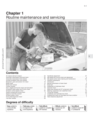 2
2 3
3 4
4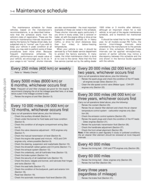 5
5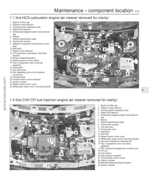 6
6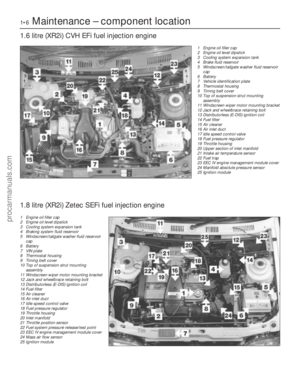 7
7 8
8 9
9 10
10 11
11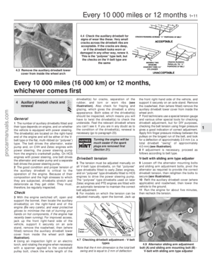 12
12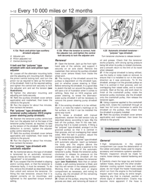 13
13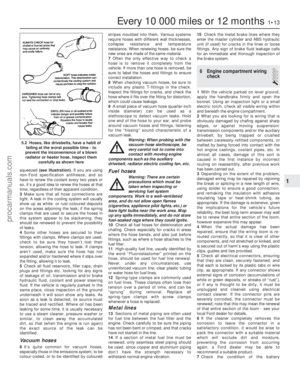 14
14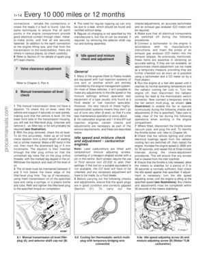 15
15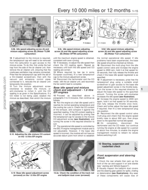 16
16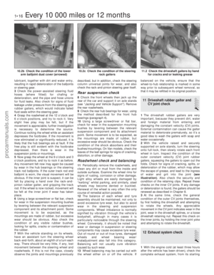 17
17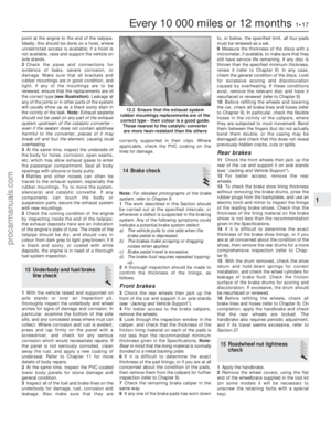 18
18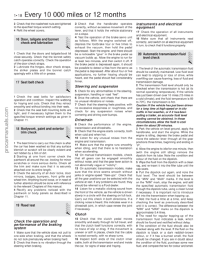 19
19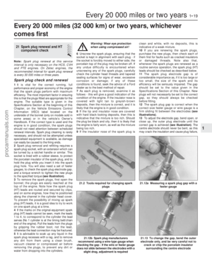 20
20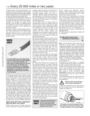 21
21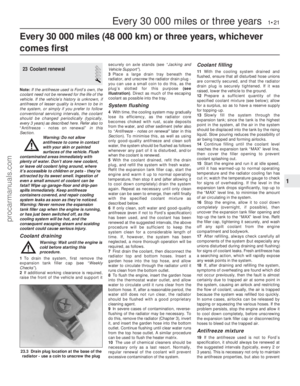 22
22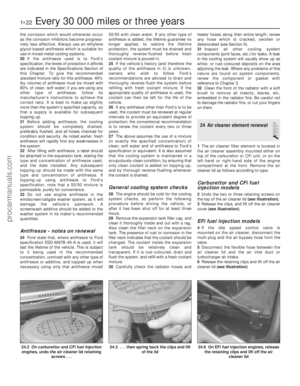 23
23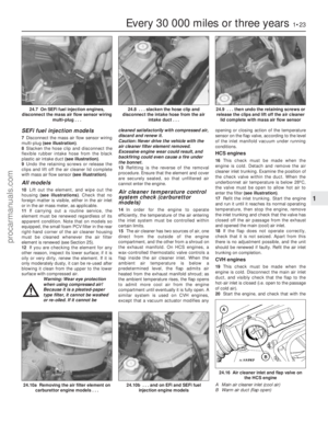 24
24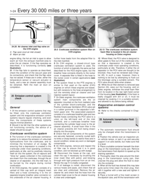 25
25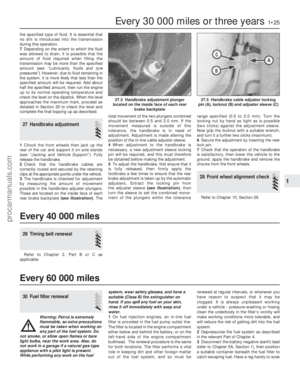 26
26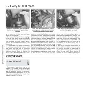 27
27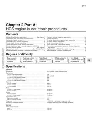 28
28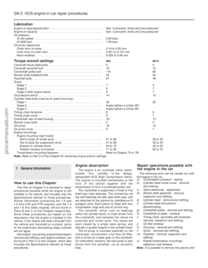 29
29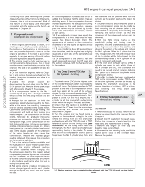 30
30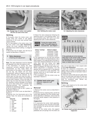 31
31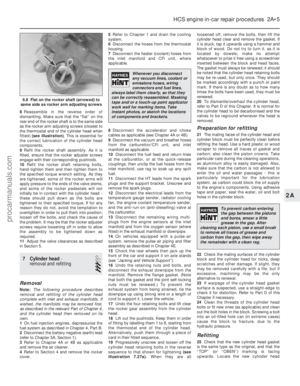 32
32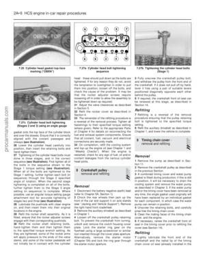 33
33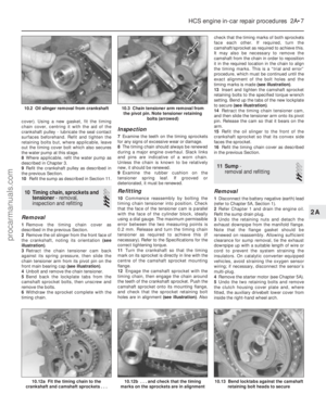 34
34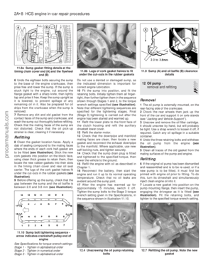 35
35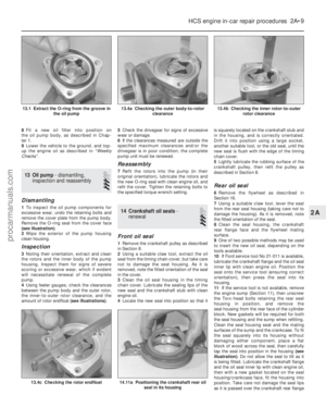 36
36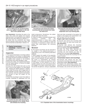 37
37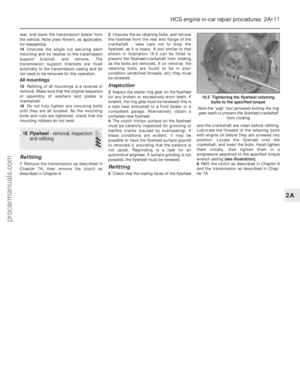 38
38 39
39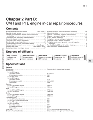 40
40 41
41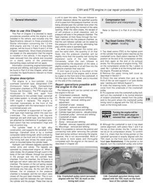 42
42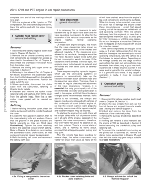 43
43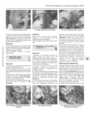 44
44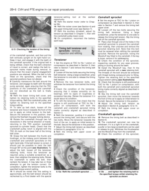 45
45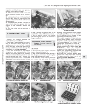 46
46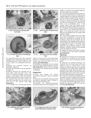 47
47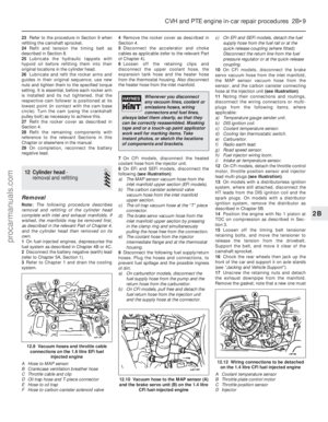 48
48 49
49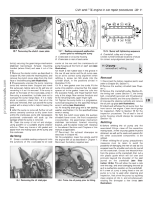 50
50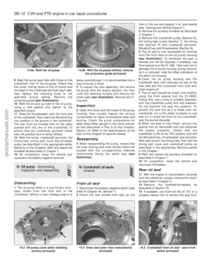 51
51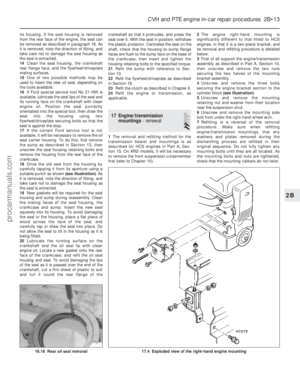 52
52 53
53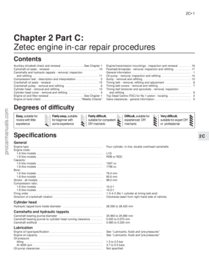 54
54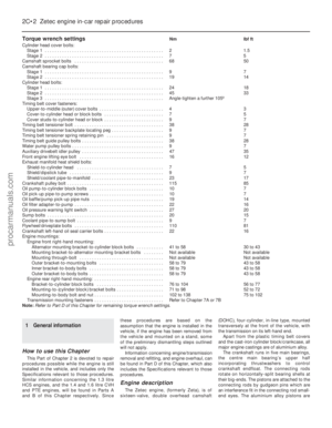 55
55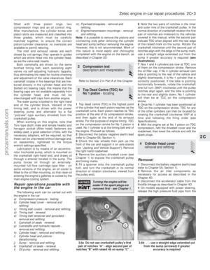 56
56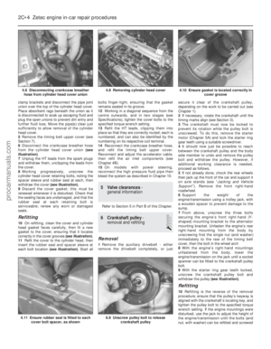 57
57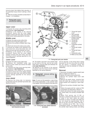 58
58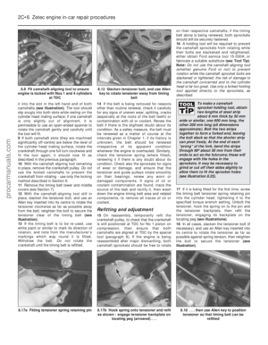 59
59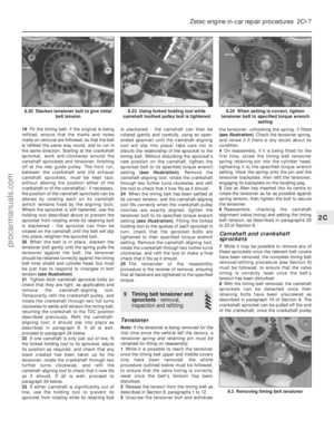 60
60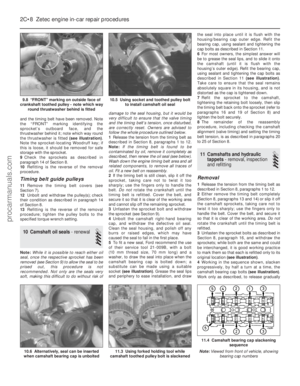 61
61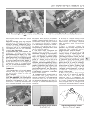 62
62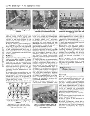 63
63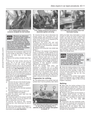 64
64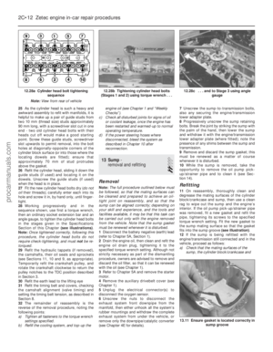 65
65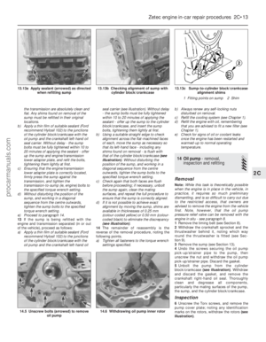 66
66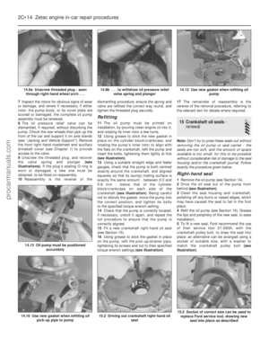 67
67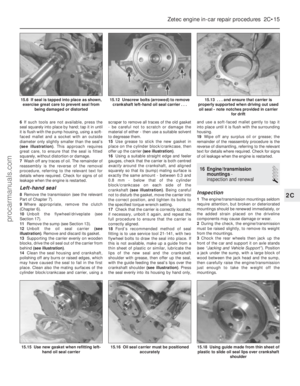 68
68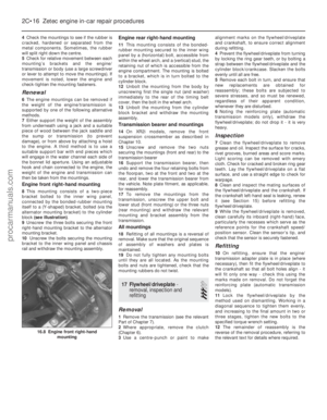 69
69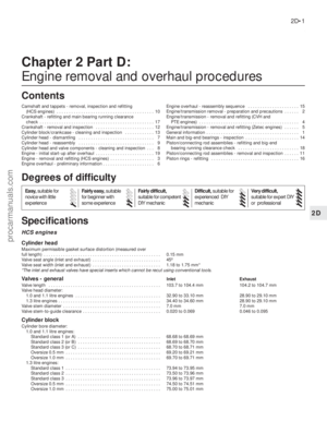 70
70 71
71 72
72 73
73 74
74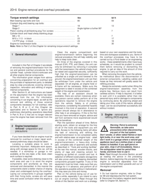 75
75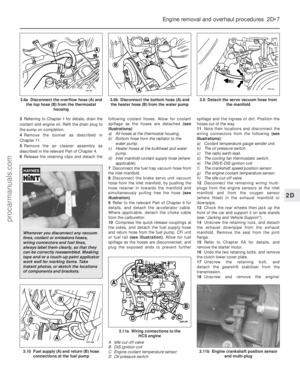 76
76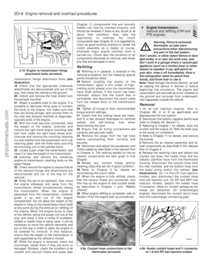 77
77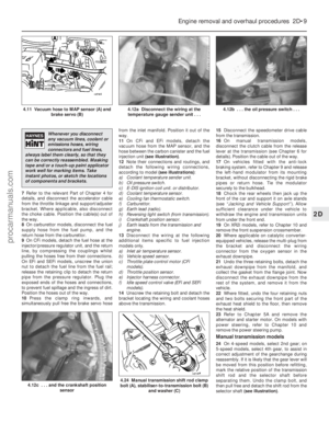 78
78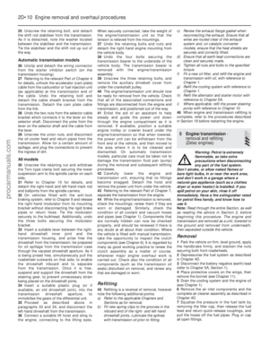 79
79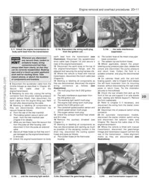 80
80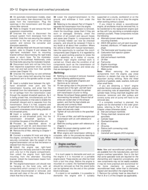 81
81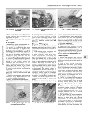 82
82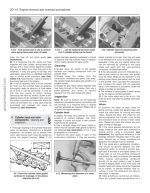 83
83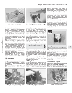 84
84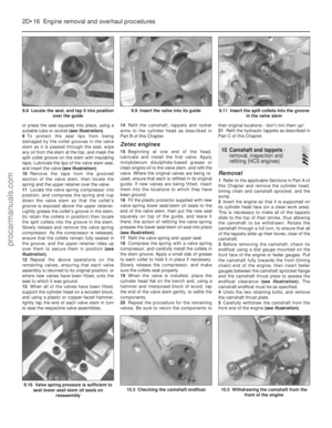 85
85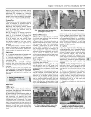 86
86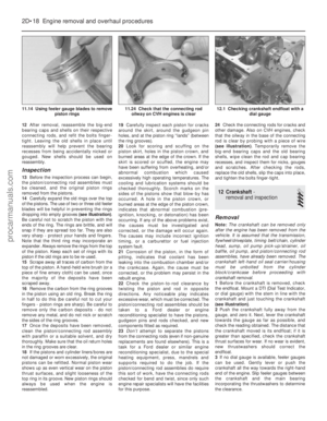 87
87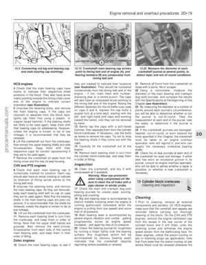 88
88 89
89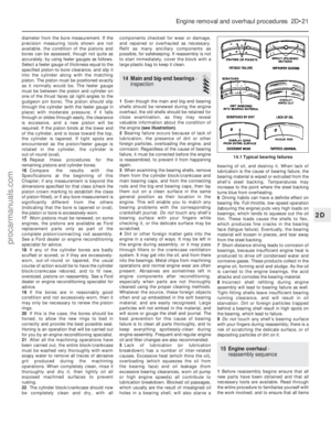 90
90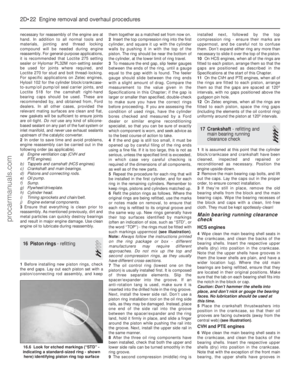 91
91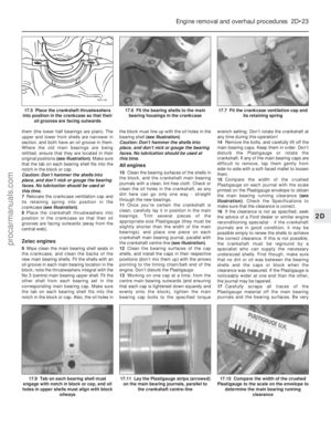 92
92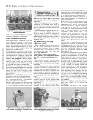 93
93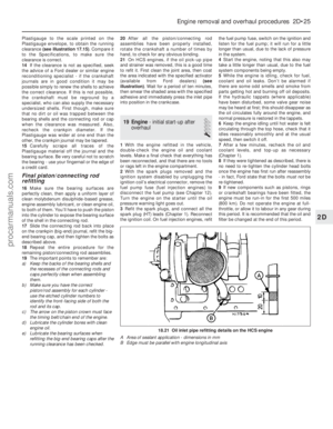 94
94 95
95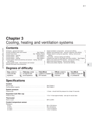 96
96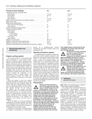 97
97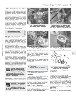 98
98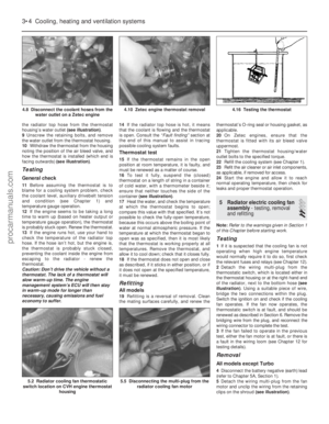 99
99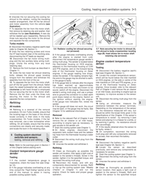 100
100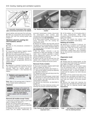 101
101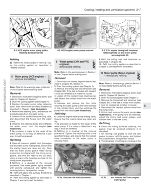 102
102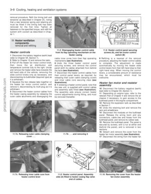 103
103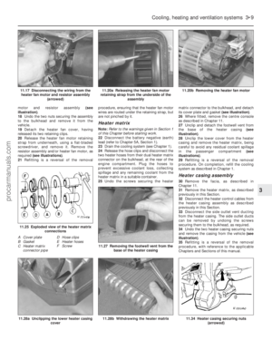 104
104 105
105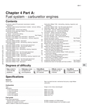 106
106 107
107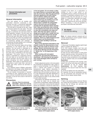 108
108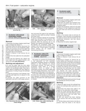 109
109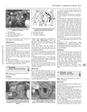 110
110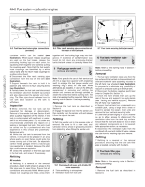 111
111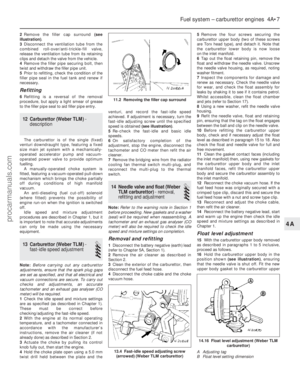 112
112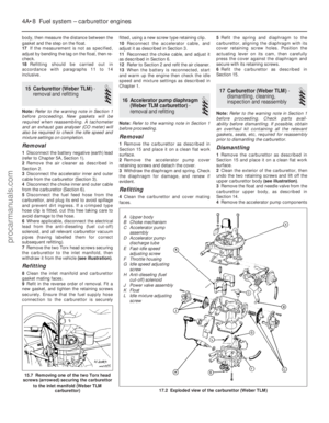 113
113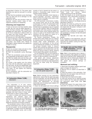 114
114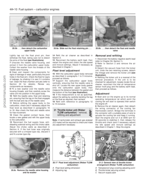 115
115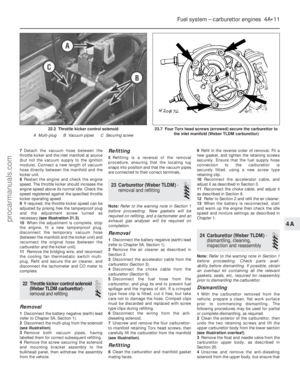 116
116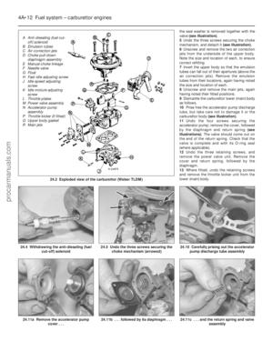 117
117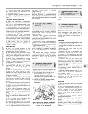 118
118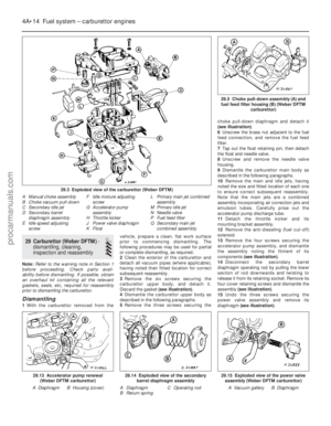 119
119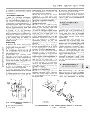 120
120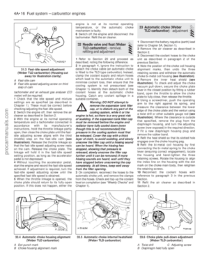 121
121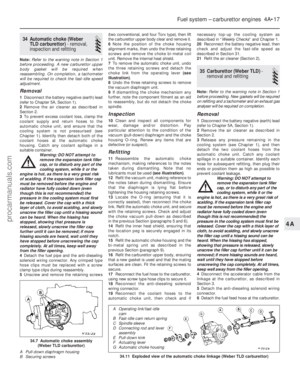 122
122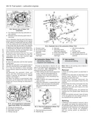 123
123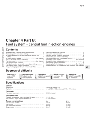 124
124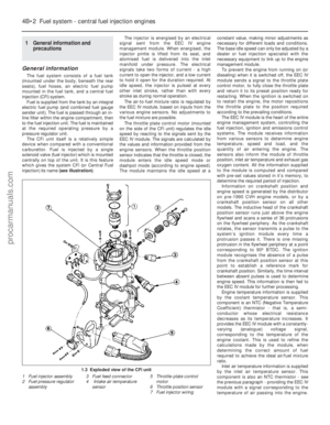 125
125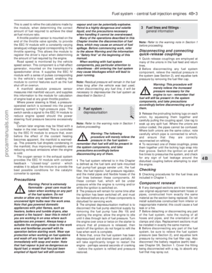 126
126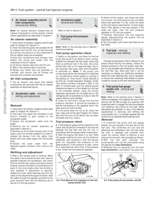 127
127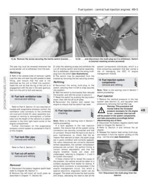 128
128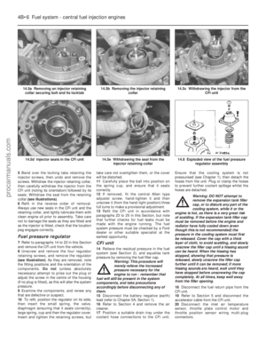 129
129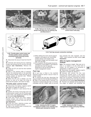 130
130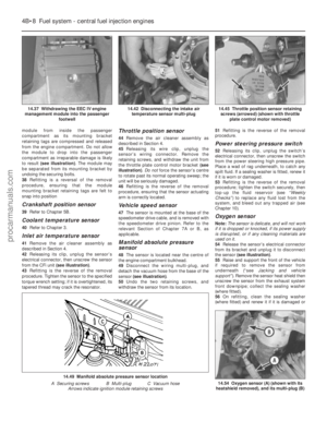 131
131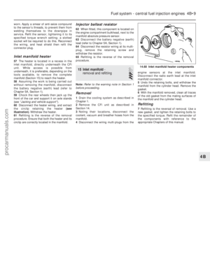 132
132 133
133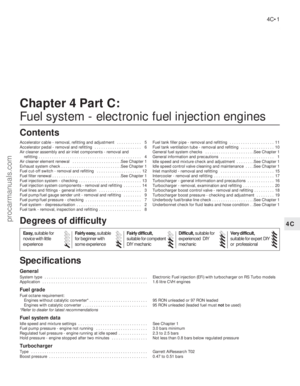 134
134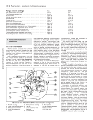 135
135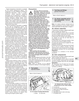 136
136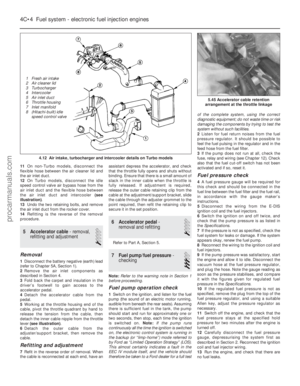 137
137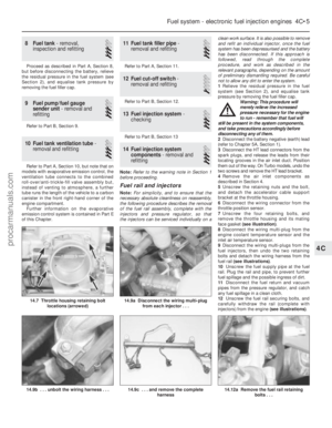 138
138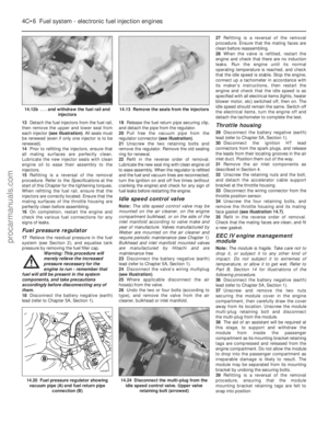 139
139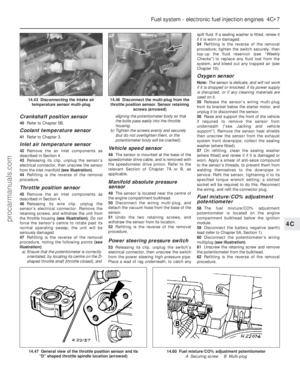 140
140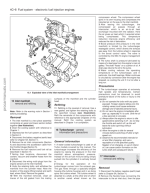 141
141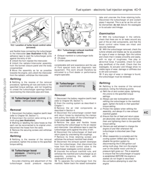 142
142 143
143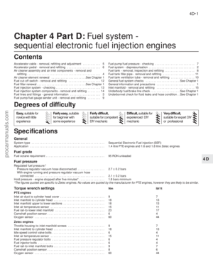 144
144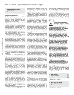 145
145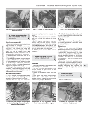 146
146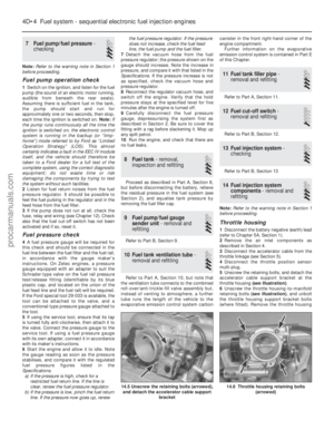 147
147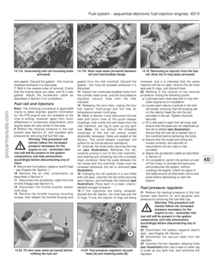 148
148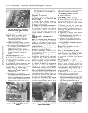 149
149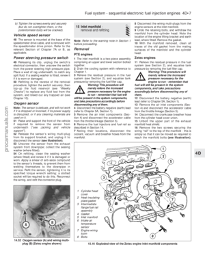 150
150 151
151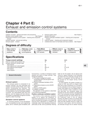 152
152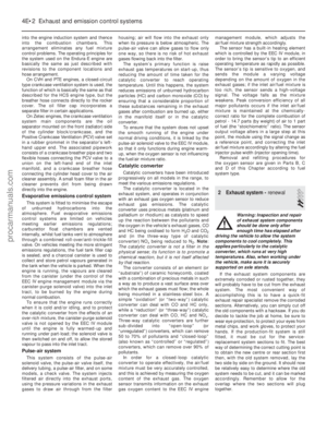 153
153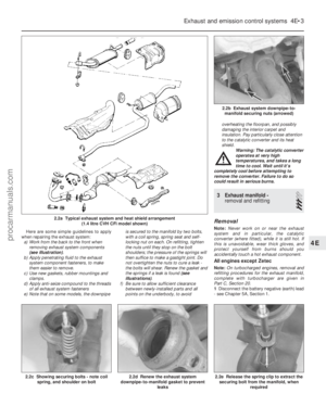 154
154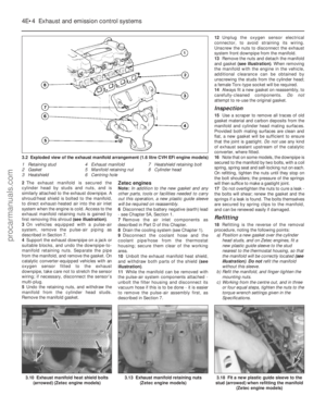 155
155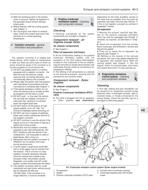 156
156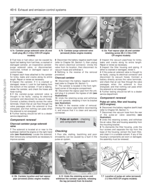 157
157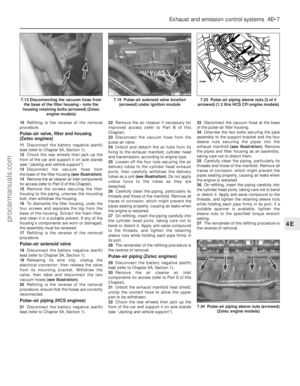 158
158 159
159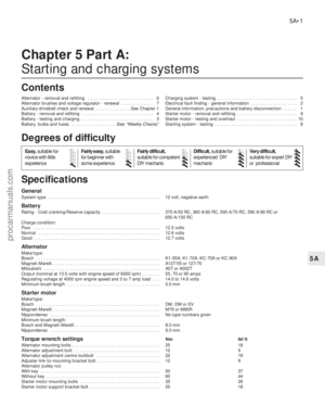 160
160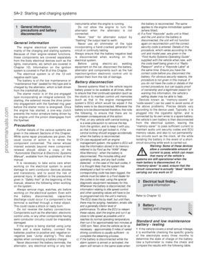 161
161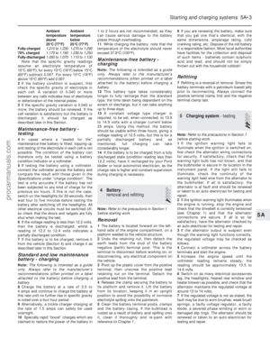 162
162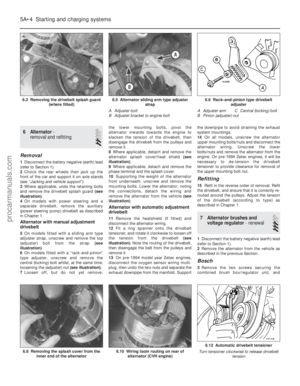 163
163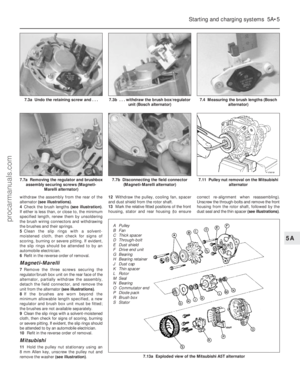 164
164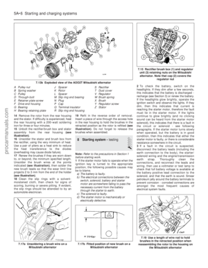 165
165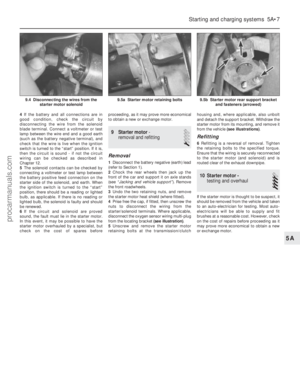 166
166 167
167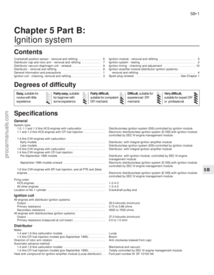 168
168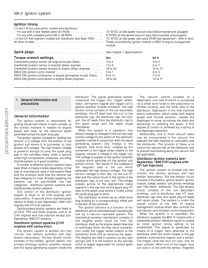 169
169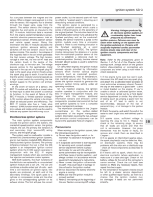 170
170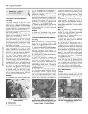 171
171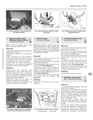 172
172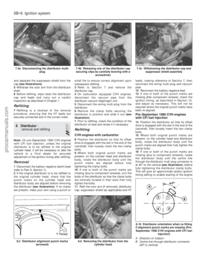 173
173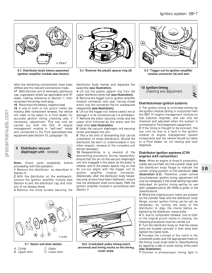 174
174 175
175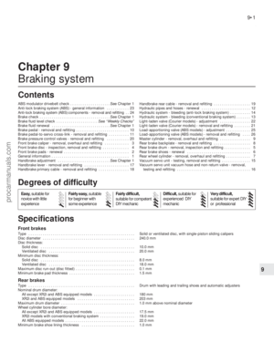 176
176 177
177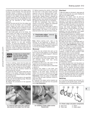 178
178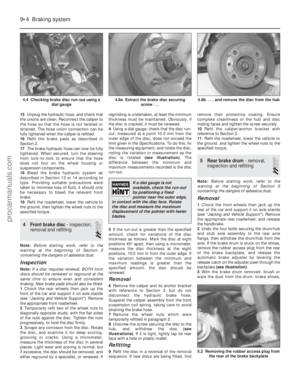 179
179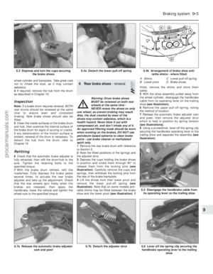 180
180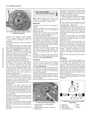 181
181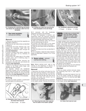 182
182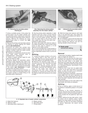 183
183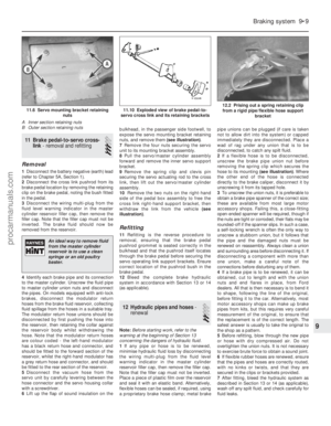 184
184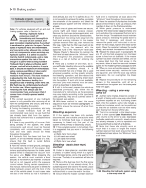 185
185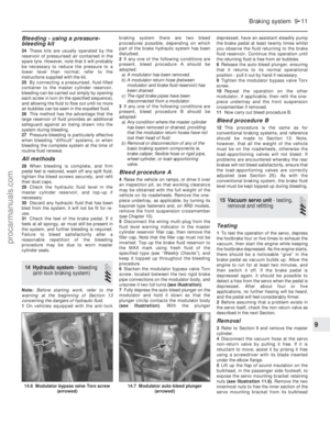 186
186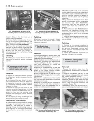 187
187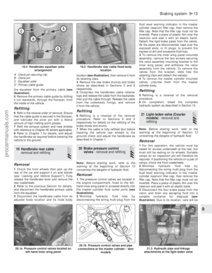 188
188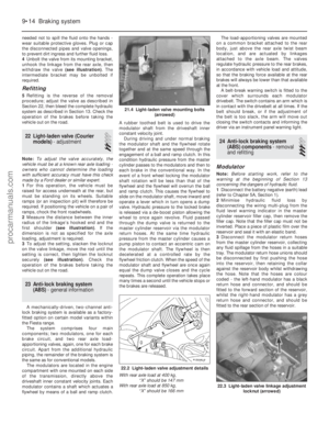 189
189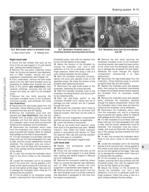 190
190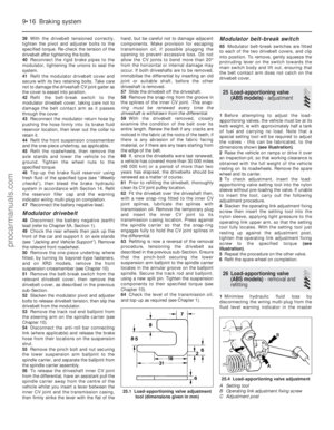 191
191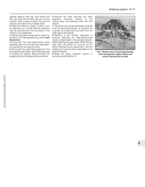 192
192 193
193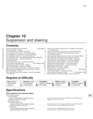 194
194 195
195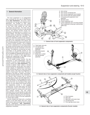 196
196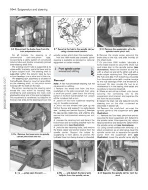 197
197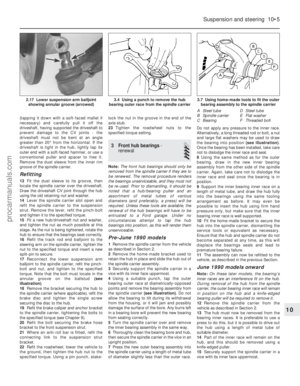 198
198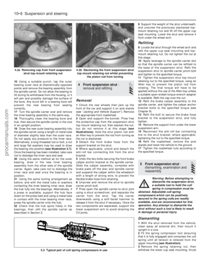 199
199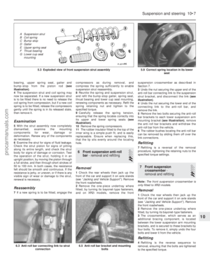 200
200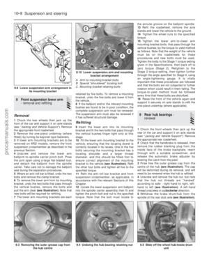 201
201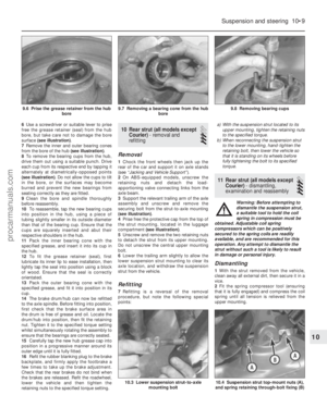 202
202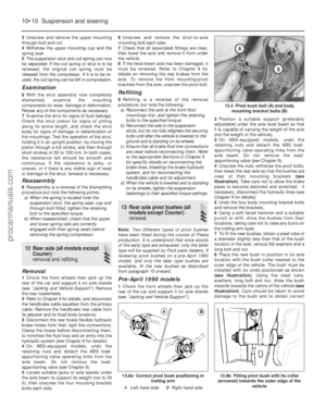 203
203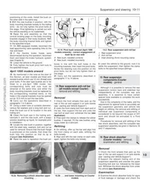 204
204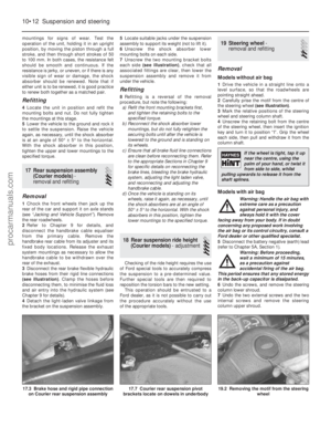 205
205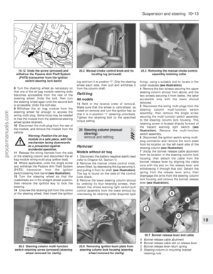 206
206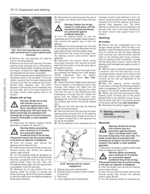 207
207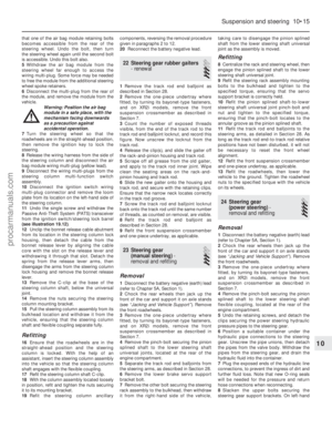 208
208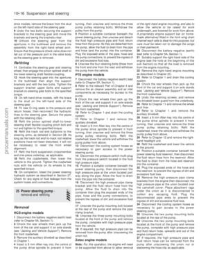 209
209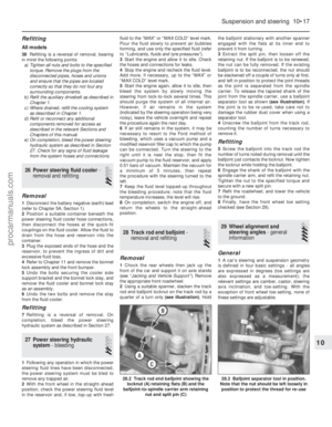 210
210 211
211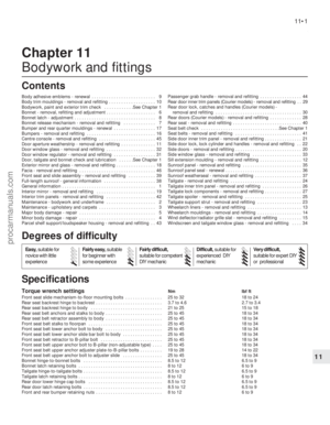 212
212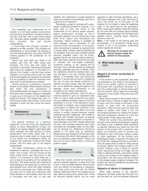 213
213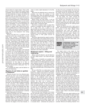 214
214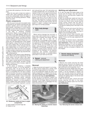 215
215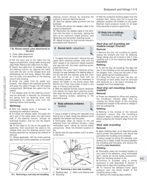 216
216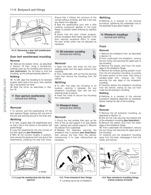 217
217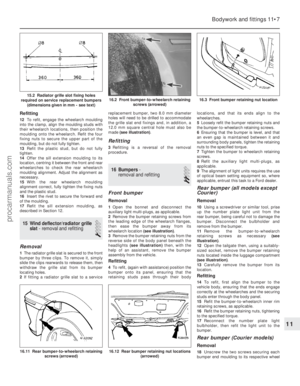 218
218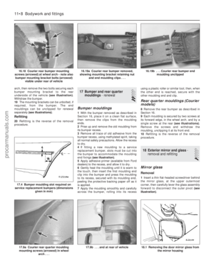 219
219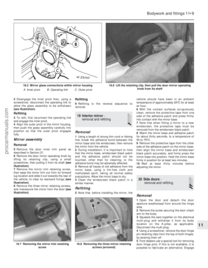 220
220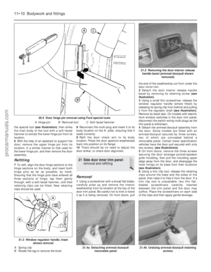 221
221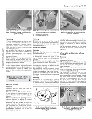 222
222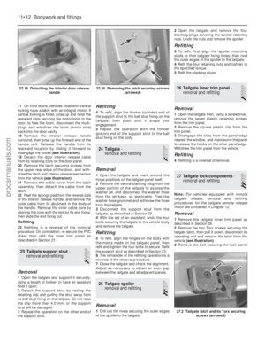 223
223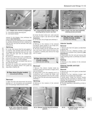 224
224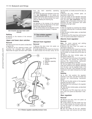 225
225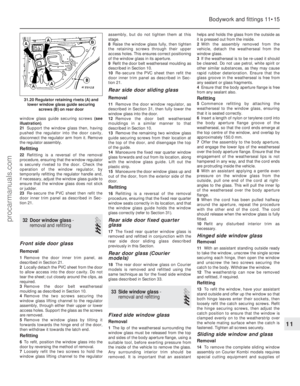 226
226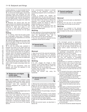 227
227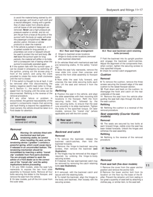 228
228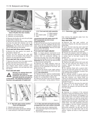 229
229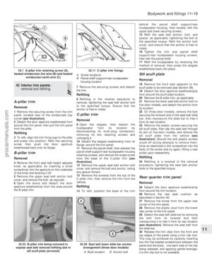 230
230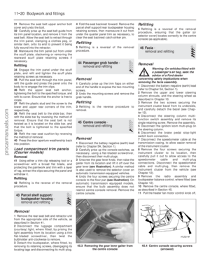 231
231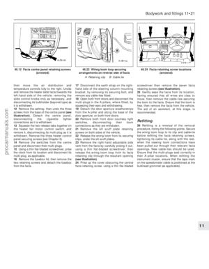 232
232 233
233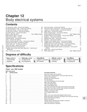 234
234 235
235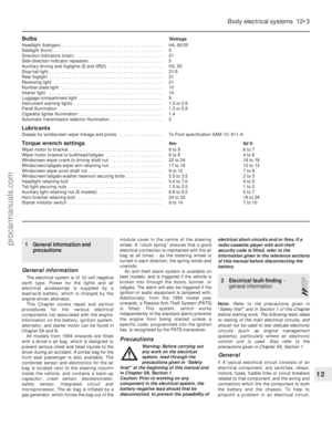 236
236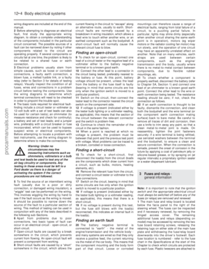 237
237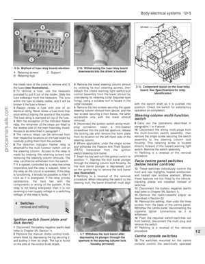 238
238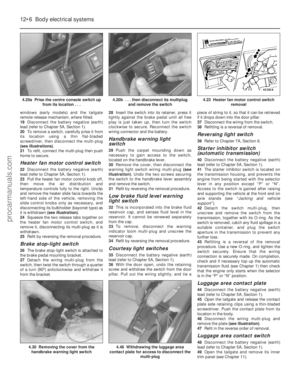 239
239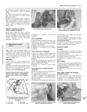 240
240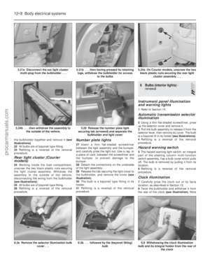 241
241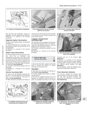 242
242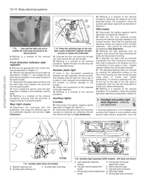 243
243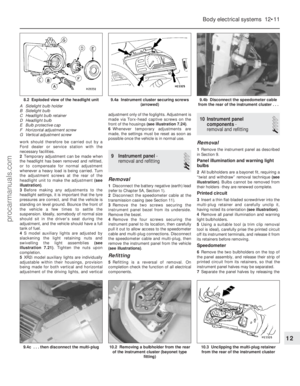 244
244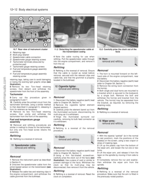 245
245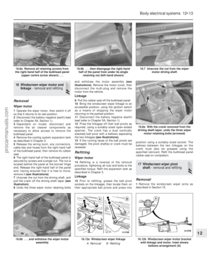 246
246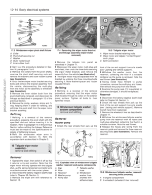 247
247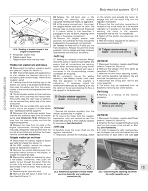 248
248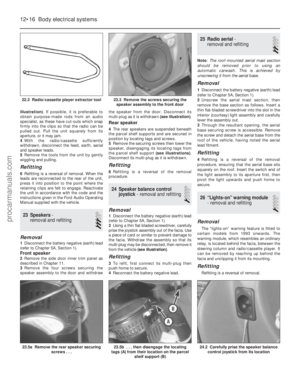 249
249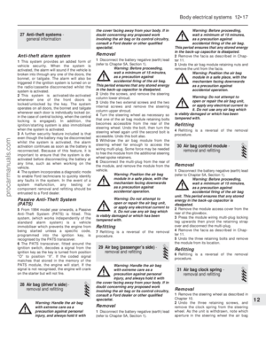 250
250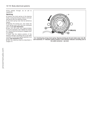 251
251 252
252 253
253 254
254 255
255 256
256 257
257 258
258 259
259 260
260 261
261 262
262 263
263 264
264 265
265 266
266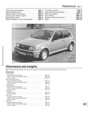 267
267 268
268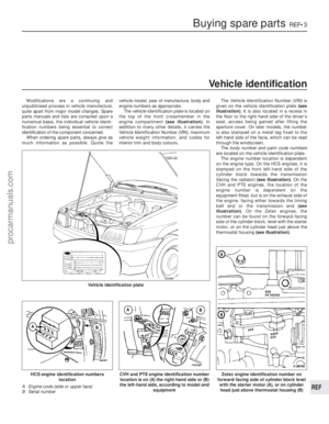 269
269 270
270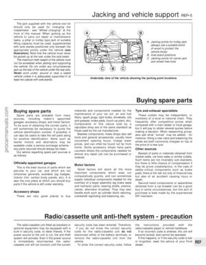 271
271 272
272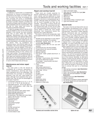 273
273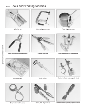 274
274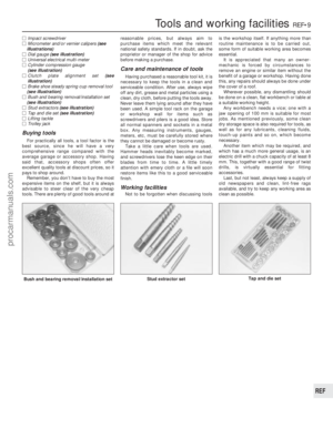 275
275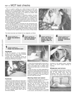 276
276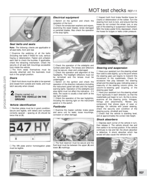 277
277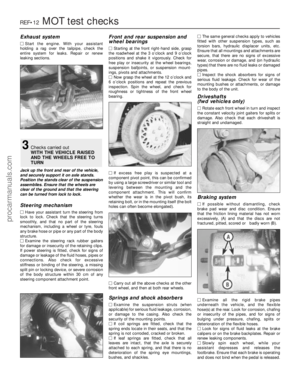 278
278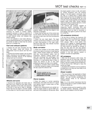 279
279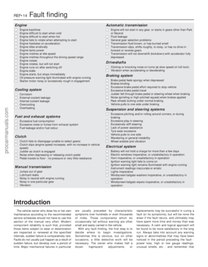 280
280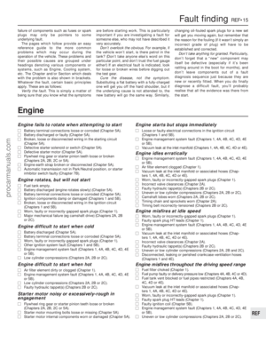 281
281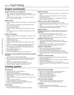 282
282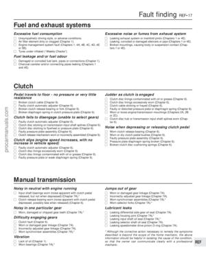 283
283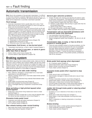 284
284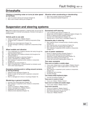 285
285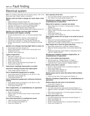 286
286 287
287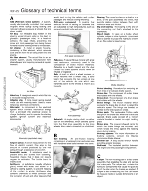 288
288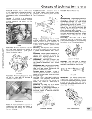 289
289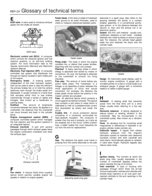 290
290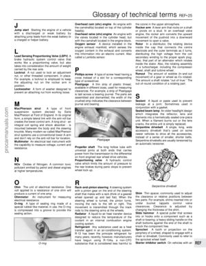 291
291 292
292 293
293 294
294 295
295