Page 185 of 296

3
Note: For vehicles equipped with an anti-lock
braking system, refer to Section 14. Warning: Hydraulic fluid is
poisonous; wash off
immedia")
13 Hydraulic system- bleeding
(conventional braking system)
3
Note: For vehicles equipped with an anti-lock
braking system, refer to Section 14. Warning: Hydraulic fluid is
poisonous; wash off
immediately and thoroughly in
the case of skin contact, and
seek immediate medical advice if any fluid
is swallowed or gets into the eyes. Certain
types of hydraulic fluid are inflammable,
and may ignite when allowed into contact
with hot components; when servicing any
hydraulic system, it is safest to assume
that the fluid IS inflammable, and to take
precautions against the risk of fire as
though it is petrol that is being handled.
Hydraulic fluid is also an effective paint
stripper, and will attack plastics; if any is
spilt, it should be washed off immediately,
using copious quantities of clean water.
Finally, it is hygroscopic (it absorbs
moisture from the air). The more moisture
is absorbed by the fluid, the lower its
boiling point becomes, leading to a
dangerous loss of braking under hard use.
Old fluid may be contaminated and unfit
for further use. When topping-up or
renewing the fluid, always use the
recommended type, and ensure that it
comes from a freshly-opened sealed
container.
1 The correct operation of any hydraulic
system is only possible after removing all air
from the components and circuit; and this is
achieved by bleeding the system.
2 During the bleeding procedure, add only
clean, unused hydraulic fluid of the
recommended type; never re-use fluid that
has already been bled from the system.
Ensure that sufficient fluid is available before
starting work.
3 If there is any possibility of incorrect fluid
being already in the system, the brake
components and circuit must be flushed
completely with uncontaminated, correct
fluid, and new seals should be fitted
throughout the system.
4 If hydraulic fluid has been lost from the
system, or air has entered because of a leak,
ensure that the fault is cured before
proceeding further.
5 Park the vehicle on level ground, and apply
the handbrake. Switch off the engine, then
(where applicable) depress the brake pedal
several times to dissipate the vacuum from
the servo unit. Note:When bleeding the
system, the vehicle must maintain a level
attitude, ie not tilted in any manner, to ensure
that air is not trapped within the pressure
control valves. During certain operations in
this manual, instructions are given to bleed the
brake hydraulic system with the front or the
rear of the vehicle raised. In such cases raise
the rest of the vehicle so that it maintains a level attitude, but only if it is safe to do so. If it
is not possible to achieve this safely, complete
the remainder of the operation and bleed the
brake hydraulic system with the vehicle on its
wheels.
6
Check that all pipes and hoses are secure,
unions tight and bleed screws closed.
Remove the dust caps (where applicable), and
clean any dirt from around the bleed screws.
7 Disconnect the wiring multi-plug from the
fluid level warning indicator in the master
cylinder reservoir filler cap, then remove the
filler cap. Note that the filler cap must not be
inverted. Top-up the reservoir with the
specified fluid to the “Maximum” level (see
“Weekly Checks” ). Remember to maintain the
fluid level at least above the “Minimum” level
line throughout the procedure, otherwise
there is a risk of further air entering the
system.
8 There are a number of one-man, do-it-
yourself brake bleeding kits currently available
from motor accessory shops. It is
recommended that one of these kits is used
whenever possible, as they greatly simplify
the bleeding operation, and also reduce the
risk of expelled air and fluid being drawn back
into the system. If such a kit is not available,
the basic (two-man) method must be used,
which is described in detail below.
9 If a kit is to be used, prepare the vehicle as
described previously, and follow the kit
manufacturer’s instructions, as the procedure
may vary slightly according to the type being
used; generally, they are as outlined below in
the relevant sub-section.
10 Whichever method is used, the same
sequence must be followed (paragraphs 11
and 12) to ensure the removal of all air from
the system.
Bleeding sequence
11 If the system has been only partially
disconnected, and suitable precautions were
taken to minimise fluid loss, it should be
necessary to bleed only that part of the
system (ie the primary or secondary circuit).
12 If the complete system is to be bled, then
it is suggested that you work in the following
sequence: a) Right-hand front wheel.
b) Left-hand rear wheel.
c) Left-hand front wheel.
d) Right-hand rear wheel.
Bleeding - basic (two-man)
method
13 Collect a clean glass jar, a suitable length
of plastic or rubber tubing which is a tight fit
over the bleed screw, and a ring spanner to fit
the screw. The help of an assistant will also be
required.
14 Remove the dust cap from the first screw
in the sequence (if not already done). Fit a
suitable spanner and tube to the screw, place
the other end of the tube in the jar, and pour in
sufficient fluid to cover the end of the tube.
15 Ensure that the master cylinder reservoir fluid level is maintained at least above the
“Minimum” level throughout the procedure.
16
Have the assistant fully depress the brake
pedal several times to build up pressure, then
maintain it down on the final downstroke.
17 While pedal pressure is maintained,
unscrew the bleed screw (approximately one
turn) and allow the compressed fluid and air to
flow into the jar. The assistant should maintain
pedal pressure, following the pedal down to
the floor if necessary, and should not
release the pedal until instructed to do so.
When the flow stops, tighten the bleed screw
again. Have the assistant release the pedal
slowly, and recheck the reservoir fluid level.
18 Repeat the steps given in paragraphs 16
and 17 until the fluid emerging from the bleed
screw is free from air bubbles. If the master
cylinder has been drained and refilled, and air
is being bled from the first screw in the
sequence, allow at least five seconds between
cycles for the master cylinder passages to refill.
19 When no more air bubbles appear, tighten
the bleed screw securely, remove the tube
and spanner, and refit the dust cap (where
applicable). Do not overtighten the bleed
screw.
20 Repeat the procedure on the remaining
screws in the sequence, until all air is
removed from the system and the brake pedal
feels firm again.
Bleeding - using a one-way
valve kit
21 As their name implies, these kits consist of
a length of tubing with a one-way valve fitted,
to prevent expelled air and fluid being drawn
back into the system; some kits include a
translucent container, which can be positioned
so that the air bubbles can be more easily
seen flowing from the end of the tube.
22 The kit is connected to the bleed screw,
which is then opened (see illustration). The
user returns to the driver’s seat, depresses
the brake pedal with a smooth, steady stroke,
and slowly releases it; this is repeated until
the expelled fluid is clear of air bubbles.
23 Note that these kits simplify work so
much that it is easy to forget the master
cylinder reservoir fluid level; ensure that this is
maintained at least above the “Minimum” level
at all times.
9•10 Braking system
13.22 Bleeding the hydraulic system using a one-way valve kit
1595Ford Fiesta Remakeprocarmanuals.com
http://vnx.su
Page 186 of 296

Bleeding - using a pressure-
bleeding kit
24These kits are usually operated by the
reservoir of pressurised air contained in the
spare tyre. However, note that it will probably
be necessary to reduce the pressure to a
lower level than normal; refer to the
instructions supplied with the kit.
25 By connecting a pressurised, fluid-filled
container to the master cylinder reservoir,
bleeding can be carried out simply by opening
each screw in turn (in the specified sequence),
and allowing the fluid to flow out until no more
air bubbles can be seen in the expelled fluid.
26 This method has the advantage that the
large reservoir of fluid provides an additional
safeguard against air being drawn into the
system during bleeding.
27 Pressure-bleeding is particularly effective
when bleeding “difficult” systems, or when
bleeding the complete system at the time of
routine fluid renewal.
All methods
28 When bleeding is complete, and firm
pedal feel is restored, wash off any spilt fluid,
tighten the bleed screws securely, and refit
their dust caps.
29 Check the hydraulic fluid level in the
master cylinder reservoir, and top-up if
necessary.
30 Discard any hydraulic fluid that has been
bled from the system; it will not be fit for re-
use.
31 Check the feel of the brake pedal. If it
feels at all spongy, air must still be present in
the system, and further bleeding is required.
Failure to bleed satisfactorily after a
reasonable repetition of the bleeding
procedure may be due to worn master
cylinder seals.
14 Hydraulic system - bleeding
(anti-lock braking system)
3
Note: Before starting work, refer to the
warning at the beginning of Section 13
concerning the dangers of hydraulic fluid.
1 On vehicles equipped with the anti-lock braking system there are two bleed
procedures possible, depending on which
part of the brake hydraulic system has been
disturbed.
2
If any one of the following conditions are
present, bleed procedure A should be
adopted: a) A modulator has been removed.
b) A modulator return hose (between
modulator and brake fluid reservoir) has
been drained.
c) The rigid brake pipes have been disconnected from a modulator.
3 If any one of the following conditions are
present, bleed procedure B should be
adopted: a) Any condition where the master cylinder
has been removed or drained, providing
that the modulator return hoses have not
lost their head of fluid.
b) Removal or disconnection of any of the
basic braking system components ie,
brake caliper, flexible hose or rigid pipe,
wheel cylinder, or load-apportioning
valve.
Bleed procedure A
4Raise the vehicle on ramps, or drive it over
an inspection pit, so that working clearance
may be obtained with the full weight of the
vehicle on its roadwheels. Remove the one-
piece undertray, as applicable, by turning its
bayonet-type fasteners and, on XR2i models,
remove the front suspension crossmember
(see Chapter 10).
5 Disconnect the wiring multi-plug from the
fluid level warning indicator in the master
cylinder reservoir filler cap, then remove the
filler cap. Note that the filler cap must not be
inverted. Top-up the brake fluid reservoir to
the MAX mark using fresh fluid of the
specified type (see “Weekly Checks”), and
keep it topped up throughout the bleeding
procedure.
6 Slacken the modulator bypass valve Torx
screw, located between the two rigid brake
pipe connections on the modulator body, and
unscrew it two full turns (see illustration).
7 Fully depress the auto-bleed plunger on the
modulator and hold it down so that the
plunger circlip contacts the modulator body
(see illustration) . With the plunger depressed, have an assistant steadily pump
the brake pedal at least twenty times whilst
you observe the fluid returning to the brake
fluid reservoir. Continue this operation until
the returning fluid is free from air bubbles.
8
Release the auto-bleed plunger, ensuring
that it returns to its normal operational
position - pull it out by hand if necessary.
9 Tighten the modulator bypass valve Torx
screw.
10 Repeat the operation on the other
modulator, if applicable, then refit the one-
piece undertray and the front suspension
crossmember if removed.
11 Now carry out bleed procedure B.
Bleed procedure B
12This procedure is the same as for
conventional braking systems, and reference
should be made to Section 13. Note,
however, that all the weight of the vehicle
must be on the roadwheels, otherwise the
load-apportioning valves will not bleed. If
problems are encountered whereby the rear
brakes will not bleed satisfactorily, ensure that
the load-apportioning valves are correctly
adjusted (see Section 25). As with the
conventional braking system, the brake fluid
level must be kept topped up during bleeding.
15 Vacuum servo unit - testing,
removal and refitting
3
Testing
1 To test the operation of the servo, depress
the footbrake four or five times to exhaust the
vacuum, then start the engine while keeping
the footbrake depressed. As the engine starts,
there should be a noticeable “give” in the
brake pedal as vacuum builds up. Allow the
engine to run for at least two minutes, and
then switch it off. If the brake pedal is
depressed again, it should be possible to
detect a hiss from the servo when the pedal is
depressed. After about four or five
applications, no further hissing will be heard,
and the pedal will feel considerably firmer.
2 Before assuming that a problem exists in
the servo itself, check the non-return valve as
described in the next Section.
Removal
3 Refer to Section 9 and remove the master
cylinder.
4 Disconnect the vacuum hose at the servo
non-return valve by pulling it free. If it is
reluctant to move, assist it by prising it free
using a screwdriver with its blade inserted
under the elbow flange.
5 Lift up the flap of sound insulation on the
bulkhead, in the passenger side footwell, to
expose the servo mounting bracket retaining
nuts (see illustration 11.6) . Remove the two
innermost nuts to free the inner section of the
servo mounting bracket from its bulkhead
Braking system 9•11
14.7 Modulator auto-bleed plunger (arrowed)14.6 Modulator bypass valve Torx screw (arrowed)
9
1595Ford Fiesta Remakeprocarmanuals.com
http://vnx.su
Page 187 of 296

location. Slacken the other two nuts or
remove them, as necessary.
6Remove the four nuts securing the servo
unit to its mounting bracket assembly, then
pull the servo forward to remove the inner
servo support bracket (see illustration).
7 Remove the spring clip and clevis pin
securing the servo pushrod to the cross link,
then lift out the servo unit (see illustration).
8 Note that the servo unit cannot be
dismantled for repair or overhaul and, if faulty,
must be renewed.
Refitting
9 Refitting is a reversal of removal. Refer to
Section 9 for details of refitting the master
cylinder.
16 Vacuum servo unit vacuum
hose and non-return valve -
removal, testing and refitting
1
Removal
1 Depress the brake pedal three or four times
to exhaust any remaining vacuum from the
servo unit.
2 Carefully pull free and detach the servo
vacuum hose from the servo unit. If the hose
is reluctant to move, prise it free with the aid
of a screwdriver, inserting its blade under the
flange of the elbow.
3 Detach the vacuum hose from its inlet
manifold connection. Depending on the fixing,
undo the union nut and withdraw the hose, or
press the hose and its retaining collar
inwards, then holding the collar in, withdraw
the hose.
4 If the hose or the fixings are damaged or in
poor condition, they must be renewed.
Non-return valve testing
5 Examine the non-return valve for damage
and signs of deterioration, and renew it if
necessary. The valve may be tested by
blowing through its connecting hoses in
both directions. It should only be possible
to blow from the servo end to the manifold
end.
Refitting
6 Refitting is a reversal of removal. If fitting a
new non-return valve, ensure that it is fitted
the correct way round.
17 Handbrake lever -
removal and refitting
1
Removal
1 Disconnect the battery negative (earth) lead
(refer to Chapter 5A, Section 1), then chock
the wheels to secure the vehicle.
2 Undo the bolts securing the front seats to
the floorpan, and remove both seats from the
vehicle (see Chapter 11). Move the seats on
their slide mechanisms to expose the
mounting bolts, as necessary.
3 Remove the screws securing the rear seat
cushion, then raise the cushion to obtain
access to the carpet retaining screws.
Remove the carpet retaining screws.
4 Undo the bolt securing the seat belt clips to
the centre of the floorpan, then remove the
clip assembly.
5 Remove the seat belt lower anchor bracket
bolt from its location at the base of the B-pillar
behind the driver’s seat.
6 Remove the screws securing the sill scuff
plate to the driver’s side of the vehicle, then
carefully pull the sill scuff plate away from its
location so that the carpet is released. 7
Fold the carpet forwards, at the same time
carefully easing it out from under the sill scuff
plate. Lift the carpet over the handbrake lever.
8 Lift out the noise insulation for access to
the lever mounting bolts and the primary
cable fixing.
9 Fully release the handbrake lever, then
remove the handbrake primary cable clevis
pin securing clip (see illustration).
Remove the clevis pin and withdraw the
primary cable from the handbrake lever
assembly.
10 Remove the cover (see illustration), then
disconnect the handbrake warning light
switch wiring connection, and undo the two
screws securing the switch to the handbrake
lever assembly.
11 Undo the handbrake lever mounting bolts,
then withdraw the handbrake lever assembly
from the vehicle.
Refitting
12 Refitting is the reverse procedure to
removal, ensuring that the handbrake warning
light wiring is routed away from the lever
ratchet. The loom should be secured to the
floorpan with tape.
13 Check the handbrake adjustment as
described in Chapter 1 to complete.
18 Handbrake primary cable -
removal and refitting
1
Removal
1 Release the primary cable from the
handbrake lever, as described in the previous
Section.
2 Chock the front wheels then jack up the
rear of the car and support it on axle stands
(see “Jacking and Vehicle Support” ).
3 Where applicable, detach the exhaust
system and remove the heat shields from the
underside floorpan to allow access to the
primary cable connections underneath the
vehicle (see Chapter 4E).
4 Release the spring clip securing the pin,
and extract the equaliser/cable pin. Detach
9•12 Braking system
17.10 Removing the cover from the
handbrake warning light switch17.9 Removing the handbrake primary cable clevis pin securing clip
15.7 Spring clip (A) and clevis pin (B)
securing servo pushrod to the cross link15.6 Nuts securing servo unit to its
mounting bracket assembly (arrowed)
1595Ford Fiesta Remakeprocarmanuals.com
http://vnx.su
Page 188 of 296
 .
5 Remove the primary cable guide by drifting
it out rearwards, through the floorpan, from
the inside of the vehicle.
Refitting
6 Refit in the")
the equaliser from the primary cable (see
illustration) .
5 Remove the primary cable guide by drifting
it out rearwards, through the floorpan, from
the inside of the vehicle.
Refitting
6 Refit in the reverse order of removal. Ensure
that the cable guide is secured in the floorpan,
and lubricate the pivot pin with a liberal
amount of high-melting-point grease.
7 Refit the exhaust system and heat shields
with reference to Chapter 4E (where applicable).
8 Refer to Chapter 1 for details, and adjust
the handbrake as required before lowering the
vehicle to the ground.
19 Handbrake rear cable -
removal and refitting
2
Removal
1 Chock the front wheels then jack up the
rear of the car and support it on axle stands
(see “Jacking and Vehicle Support” ). Fully
release the handbrake lever and remove the
rear roadwheels.
2 Refer to the previous Section for details,
and disconnect the handbrake primary cable
from the equaliser.
3 Disconnect the handbrake cable from its
adjuster body location and its fixed body location
(see illustration) , then remove it from
its retaining clips.
4 Remove the rear brake drum(s) and brake
shoes as described in Sections 5 and 6
respectively.
5 Compress the handbrake cable retainer
lugs and release the cable from the backplate,
then pull the cable through. Release the cable
from the underbody fixings, and remove
it from the vehicle.
Refitting
6 Refitting is a reversal of the removal
procedure. Refer to Sections 6 and 5
respectively for details on the refitting of the
brake shoes and drums.
7 When the cable is fully refitted (but before
lowering the vehicle rear wheels to the
ground) check and adjust the handbrake as
described in Chapter 1.
20 Brake pressure control valves - removal and refitting
3
Note: Before starting work, refer to the
warning at the beginning of Section 13
concerning the dangers of hydraulic fluid.
Removal
1 The pressure control valves are located in
the engine compartment, fixed to the left-
hand inner wing panel or screwed directly into
the master cylinder fluid outlet ports (see
illustrations) .
2 Minimise hydraulic fluid loss by
disconnecting the wiring multi-plug from the fluid level warning indicator in the master
cylinder reservoir filler cap, then remove the
filler cap. Note that the filler cap must not be
inverted. Place a piece of plastic film over the
reservoir and seal it with an elastic band.
Detach the rigid brake pipes from the valves.
As the pipes are disconnected, tape over the
exposed ends, or fit plugs, to prevent the
ingress of dirt and excessive fluid loss.
3
To remove the inner wing panel mounted
assembly, remove the two screws securing
the valve assembly mounting bracket to the
inner wing panel, and withdraw the valve
assembly from the vehicle. To remove the
valves from the bracket, slide free the
retaining clips and detach the valve(s).
4 To remove the master cylinder mounted
valves, unscrew them from the master
cylinder body.
Refitting
5 Refitting is a reversal of the removal
procedure.
6 On completion, bleed the complete
hydraulic system as described in Section 13.
21 Light-laden valve (Courier models) - removal and
refitting
3
Note: Before starting work, refer to the
warning at the beginning of Section 13
concerning the dangers of hydraulic fluid.
Removal
1 For this operation, the vehicle must be
raised for access underneath at the rear, but
must still be resting on its wheels. Suitable
ramps (or an inspection pit) will therefore be
required. If positioning the vehicle on a pair of
ramps, chock the front roadwheels.
2 Minimise hydraulic fluid loss by
disconnecting the wiring multi-plug from the
fluid level warning indicator in the master
cylinder reservoir filler cap, then remove the
filler cap. Note that the filler cap must not be
inverted. Place a piece of plastic film over the
reservoir and seal it with an elastic band.
3 Disconnect the four brake pipes from the
valve, and drain any escaping fluid into a
suitable container for disposal (see
illustration) . Due to its location, care will be
Braking system 9•13
19.3 Handbrake rear cable fixed body
location18.4 Handbrake equaliser yokearrangement
A Clevis pin securing clip
B Clevis pin
C Equaliser yoke
D Primary cable guide
21.3 Hydraulic pipe and linkage
attachments at the light-laden valve20.1b Pressure control valves and pipe
connections at the master cylinder - later
models20.1a Pressure control valves located onleft-hand inner wing panel
9
1595Ford Fiesta Remakeprocarmanuals.com
http://vnx.su
Page 189 of 296

needed not to spill the fluid onto the hands -
wear suitable protective gloves. Plug or cap
the disconnected pipes and valve openings,
to prevent dirt ingress and further fluid loss.
4Unbolt the valve from its mounting bracket,
unhook the linkage from the rear axle, then
withdraw the valve (see illustration). The
intermediate bracket may be unbolted if
required.
Refitting
5 Refitting is the reverse of the removal
procedure; adjust the valve as described in
Section 22, then bleed the complete hydraulic
system as described in Section 13. Check the
operation of the brakes before taking the
vehicle out on the road.
22 Light-laden valve (Courier models) - adjustment
2
Note:To adjust the valve accurately, the
vehicle must be at a known rear axle loading -
owners who cannot determine the loading
with sufficient accuracy must have this check
made by a Ford dealer or similar expert.
1 For this operation, the vehicle must be
raised for access underneath at the rear, but
must be standing on its wheels. Suitable
ramps (or an inspection pit) will therefore be
required. If positioning the vehicle on a pair of
ramps, chock the front roadwheels.
2 Measure the distance between the inner
radius of the linkage’s hooked end and the
first shoulder (see illustration) . If the
dimension is not as specified for the axle
loading, adjustment is required.
3 To adjust the setting, slacken the locknut
on the valve linkage, move the rod until the
setting is correct, then tighten the locknut
securely (see illustration) . Check the
operation of the brakes before taking the
vehicle out on the road.
23 Anti-lock braking system (ABS) - general information
A mechanically-driven, two-channel anti-
lock braking system is available as a factory-
fitted option on certain model variants within
the Fiesta range.
The system comprises four main
components; two modulators, one for each
brake circuit, and two rear axle load-
apportioning valves, again, one for each brake
circuit. Apart from the additional hydraulic
piping, the remainder of the braking system is
the same as for conventional models. The modulators are located in the engine
compartment with one mounted on each side
of the transmission, directly above the
driveshaft inner constant velocity joints. Each
modulator contains a shaft which actuates a
flywheel by means of a ball and ramp clutch. A rubber toothed belt is used to drive the
modulator shaft from the driveshaft inner
constant velocity joint.
During driving and under normal braking
the modulator shaft and the flywheel rotate
together and at the same speed through the
engagement of a ball and ramp clutch. In this
condition hydraulic pressure from the master
cylinder passes to the modulators and then to
each brake in the conventional way. In the
event of a front wheel locking the modulator
shaft rotation will be less than that of the
flywheel and the flywheel will overrun the ball
and ramp clutch. This causes the flywheel to
slide on the modulator shaft, move inward and
operate a lever which in turn opens a dump
valve. Hydraulic pressure to the locked brake
is released via a de-boost piston allowing the
wheel to once again revolve. Fluid passed
through the dump valve is returned to the
master cylinder reservoir via the modulator
return hoses. At the same time hydraulic
pressure from the master cylinder causes a
pump piston to contact an eccentric cam on
the modulator shaft. The flywheel is then
decelerated at a controlled rate by the
flywheel friction clutch. When the speed of the
modulator shaft and flywheel are once again
equal the dump valve closes and the cycle
repeats. This complete operation takes place
many times a second until the vehicle stops or
the brakes are released. The load-apportioning valves are mounted
on a common bracket attached to the rear
body, just above the rear axle twist beam
location, and are actuated by linkages
attached to the axle beam. The valves
regulate hydraulic pressure to the rear brakes,
in accordance with vehicle load and attitude,
so that the braking force available at the rear
brakes will always be lower than that available
at the front. A belt-break warning switch is fitted to the
cover which surrounds each modulator
drivebelt. The switch contains an arm which is
in contact with the drivebelt at all times. If the
belt should break, or if the adjustment of
the belt is too slack, the arm will move out
closing the switch contacts and informing the
driver via an instrument panel warning light.
24 Anti-lock braking system (ABS) components - removal
and refitting
3
Modulator
Note: Before starting work, refer to the
warning at the beginning of Section 13
concerning the dangers of hydraulic fluid.
1 Disconnect the battery negative (earth) lead
(refer to Chapter 5A, Section 1).
2 Minimise hydraulic fluid loss by
disconnecting the wiring multi-plug from the
fluid level warning indicator in the master
cylinder reservoir filler cap, then remove the
filler cap. Note that the filler cap must not be
inverted. Place a piece of plastic film over the
reservoir and seal it with an elastic band.
3 Disconnect the modulator return hoses
from the master cylinder reservoir, collecting
any fluid spillage from the hoses in a suitable
tray. The modulator return hose unions should
be disconnected by first pushing the hose
into the reservoir, then retaining the collar
against the reservoir body whilst withdrawing
the hose. Note that the hoses are colour
coded - the left-hand modulator has a black
return hose and connector, and should be
fitted to the forward section of the reservoir,
whilst the right-hand modulator has a grey
return hose and connector, and should be
fitted to the rear section of the reservoir.
9•14 Braking system
22.3 Light-laden valve linkage adjustment locknut (arrowed)
22.2 Light-laden valve adjustment details
With rear axle load at 400 kg, “X” should be 147 mm
With rear axle load at 850 kg,
“X” should be 166 mm
21.4 Light-laden valve mounting bolts (arrowed)
1595Ford Fiesta Remakeprocarmanuals.com
http://vnx.su
Page 190 of 296
.
5 Remove the one-piece undertray where
fitted, by turn")
Right-hand side
4Chock the rear wheels then jack up the
front of the car and support it on axle stands
(see “Jacking and Vehicle Support” ).
5 Remove the one-piece undertray where
fitted, by turning the bayonet type fasteners,
and on XR2i models, remove the front
suspension crossmember (see Chapter 10).
6 From underneath, remove the belt-break
switch from the right-hand drivebelt cover by
squeezing its release lever towards the main
body of the switch (see illustration), then
carefully withdraw, ensuring that the belt
contact arm does not catch on the drivebelt
cover.
7 Remove the two bolts securing the
modulator drivebelt cover to the modulator
mounting bracket, and withdraw the cover
(see illustration) .
8 Disconnect the rigid brake pipes from the
modulator, fitting blanking plugs to prevent
excessive fluid loss and dirt ingress.
9 Remove the modulator pivot bolt and
adjuster bolt (see illustration) , then slip the
drivebelt from its pulley, and withdraw the
modulator unit from the vehicle. Ensure that
the modulator return hose does not become
kinked as the modulator unit is withdrawn.
10 Disconnect the modulator return hose
from the modulator unit, and fit a blanking
plug to prevent dirt ingress. Allow for residual
fluid spillage as the hose is disconnected.
11 If a new modulator is to be fitted, note that
these units are not interchangeable from side
to side, and the correct replacement must be
obtained. The modulator units are colour-
coded, and must be fitted with the arrows on
top of the casings pointing towards the front
of the vehicle.
12 To refit, first connect the modulator return
hose to the return outlet on the modulator
unit.
13 Locate the modulator unit to its bracket
and fit the pivot bolt, having applied a thin
smear of anti-seize compound to the bolt, but
do not fully tighten at this stage. Take care not
to damage the modulator return hose as it is
manoeuvred into position.
14 Fit the drivebelt to its modulator pulley
location, ensuring that it sits correctly over the driveshaft pulley, then refit the adjuster bolt
but do not fully tighten at this stage.
15
Adjust the tension of the drivebelt by
moving the modulator unit, until a belt
deflection of 5.0 mm is obtained under firm
finger pressure. Check this using a ruler at a
point midway between the two pulleys.
16 With the drivebelt tensioned correctly,
tighten the pivot and adjuster bolts to the
specified torque. Re-check the tension of the
drivebelt after tightening the bolts.
17 Reconnect the rigid brake pipes to the
modulator, tightening the unions securely.
18 Refit the modulator drivebelt cover to the
modulator mounting bracket, and secure with
its two retaining bolts.
19 Refit the belt-break switch to the
modulator drivebelt cover, taking care not to
damage the belt contact arm as it passes
through the cover.
20 Reconnect the modulator return hose by
pushing the hose firmly into its brake fluid
reservoir location, then lever out the collar to
retain it.
21 Refit the front suspension crossmember
and the one-piece undertray, as applicable.
22 Lower the vehicle to the ground.
23 Top-up the brake fluid reservoir using
fresh fluid of the specified type (see “ Weekly
checks ”), then bleed the brake hydraulic
system in accordance with Section 14. Refit
the reservoir filler cap and warning indicator
wiring multi-plug on completion.
24 Reconnect the battery negative lead.
Left-hand side
25Repeat the procedures given in
paragraphs 1 to 3.
26 Chock the rear wheels then jack up the
front of the car and support it on axle stands
(see “Jacking and Vehicle Support” ). Remove
the front roadwheels.
27 Remove the one-piece undertray where
fitted, by turning the bayonet type fasteners,
and on XR2i models, remove the front
suspension crossmember (see Chapter 10).
28 Remove the belt-break switch from the
left-hand drivebelt cover in a similar manner to
that described in paragraph 6, this time from
the engine compartment. 29
Remove the two bolts securing the
modulator drivebelt cover to the modulator
mounting bracket, then ease the lower portion
of the cover over the driveshaft taking care
not to damage the driveshaft CV joint gaiter.
Withdraw the cover through the engine
compartment, manoeuvring it to clear
obstructions.
30 Disconnect the rigid brake pipes from the
modulator, fitting blanking plugs to prevent
excessive fluid loss and dirt ingress.
31 Slacken the modulator pivot and adjuster
bolts, then swing the modulator downwards
to release the drivebelt tension before slipping
the drivebelt from its modulator pulley
location.
32 Remove the modulator pivot and adjuster
bolts, withdraw the modulator upwards
through the engine compartment. Ensure that
the modulator return hose does not become
kinked as the modulator unit is withdrawn.
33 Disconnect the modulator return hose
from the modulator unit, and fit a blanking
plug to prevent dirt ingress. Allow for residual
fluid spillage as the hose is disconnected.
34 If a new modulator is to be fitted, note that
these units are not interchangeable from side
to side, and the correct replacement must be
obtained. The modulator units are colour-
coded, and must be fitted with the arrows on
top of the casings pointing towards the front
of the vehicle.
35 To refit, first connect the modulator return
hose to the return outlet on the modulator
unit.
36 Locate the modulator unit to its mounting
bracket and fit the pivot bolt, having applied a
thin smear of anti-seize compound to the bolt,
but do not fully tighten at this stage. Take care
not to damage the modulator return hose as it
is manoeuvred into position.
37 Fit the drivebelt to its modulator pulley
location, ensuring that it sits correctly over the
driveshaft pulley, then refit the adjuster bolt
but do not fully tighten at this stage.
38 Adjust the tension of the drivebelt by
moving the modulator unit, until a belt
deflection of 5.0 mm is obtained under firm
finger pressure. Check this using a ruler at a
point midway between the two pulleys.
Braking system 9•15
24.9 Modulator pivot bolt (A) and adjuster bolt (B)24.7 Modulator drivebelt cover to
mounting bracket securing bolts (arrowed)24.6 Belt-break switch in drivebelt cover
A Main switch body B Release lever
9
1595Ford Fiesta Remakeprocarmanuals.com
http://vnx.su
Page 191 of 296

39With the drivebelt tensioned correctly,
tighten the pivot and adjuster bolts to the
specified torque. Re-check the tension of the
drivebelt after tightening the bolts.
40 Reconnect the rigid brake pipes to the
modulator, tightening the unions to seal the
system.
41 Refit the modulator drivebelt cover and
secure with its two retaining bolts. Take care
not to damage the driveshaft CV joint gaiter as
the cover is eased into position.
42 Refit the belt-break switch to the
modulator drivebelt cover, taking care not to
damage the belt contact arm as it passes
through the cover.
43 Reconnect the modulator return hose by
pushing the hose firmly into its brake fluid
reservoir location, then lever out the collar to
retain it.
44 Refit the front suspension crossmember
and the one-piece undertray, as applicable.
45 Refit the roadwheels, then remove the
axle stands and lower the vehicle to the
ground. Tighten the wheel nuts to the
specified torque.
46 Top-up the brake fluid reservoir using
fresh fluid of the specified type (see “ Weekly
checks ”), then bleed the brake hydraulic
system in accordance with Section 14. Refit
the reservoir filler cap and the warning
indicator wiring multi-plug on completion.
47 Reconnect the battery negative lead.
Modulator drivebelt
48Disconnect the battery negative (earth)
lead (refer to Chapter 5A, Section 1).
49 Chock the rear wheels then jack up the
front of the car and support it on axle stands
(see “Jacking and Vehicle Support” ). Remove
the relevant front roadwheel.
50 Remove the one-piece undertray where
fitted, by turning its bayonet-type fasteners,
and on XR2i models, remove the front
suspension crossmember (see Chapter 10).
51 Remove the belt-break switch from the
relevant drivebelt cover, then remove the
drivebelt cover, as described in the previous
sub-Section.
52 Slacken the modulator pivot and adjuster
bolts to release drivebelt tension, then slip the
drivebelt from the modulator.
53 Remove the track rod end balljoint from
the steering arm on the spindle carrier (see
Chapter 10).
54 Disconnect the anti-roll bar connecting
link (where applicable) and release the brake
hose from their locations on the suspension
strut.
55 Remove the pinch bolt and nut securing
the lower suspension arm balljoint to the
spindle carrier, and separate the balljoint from
the spindle carrier assembly.
56 To release the driveshaft inner CV joint
from the differential, have an assistant pull the
spindle carrier away from the centre of the
vehicle whilst you insert a lever between the
inner CV joint and the transmission casing,
then firmly strike the lever with the flat of the hand, but be careful not to damage adjacent
components. Make provision for escaping
transmission oil, if possible plugging the
opening to prevent excessive loss. Do not
allow the CV joints to bend more than 20°
from the horizontal or internal damage may
occur. If both driveshafts are to be removed,
immobilise the differential by inserting an old
joint or suitable shaft, before the other
driveshaft is removed.
57
Slide the drivebelt off the driveshaft.
58 Remove the snap-ring from the groove in
the splines of the inner CV joint. This snap-
ring must be renewed every time the
driveshaft is withdrawn from the differential.
59 With the drivebelt removed, closely
examine the condition of the belt over its
entire length. Renew the belt if any cracks are
noticed in the fabric at the roots of the teeth, if
there is any abrasion of the fabric facing
material, or if there are any tears starting from
the edge of the belt.
60 If, since the drivebelts were last renewed,
a vehicle has covered more than 30 000 miles
(48 000 km) or a period of more than two
years has elapsed, the drivebelts should be
renewed as a matter of course.
61 Prior to refitting the drivebelt, thoroughly
clean its CV joint pulley location.
62 Fit the drivebelt over the driveshaft then,
with a new snap-ring fitted to the inner CV
joint splines, lubricate the splines with
transmission oil. Remove the temporary plug
and insert the inner CV joint to its
transmission casing location. Press against
the spindle carrier so that the snap-ring
engages fully to hold the CV joint splines in
the differential.
63 Refitting is now a reversal of the removal
procedure, tensioning the drivebelt as
described in the previous sub-Section. Ensure
that the pinch-bolt securing the lower
suspension arm balljoint to the spindle carrier
locates in the annular groove on the balljoint
spindle. Secure the track rod and balljoint,
using a new split pin. Tighten the suspension
components to their specified torque (see
Chapter 10).
64 Check the level of the transmission oil,
and top-up as required (see Chapter 1).
Modulator belt-break switch
65 Modulator belt-break switches are fitted
to each of the two drivebelt covers, and clip
into position. To remove, gently squeeze the
protruding lever on the switch towards the
main switch body and lift out, ensuring that
the belt contact arm does not catch on the
drivebelt cover.
25 Load-apportioning valve (ABS models) - adjustment
3
1Before attempting to adjust the load-
apportioning valves, the vehicle must be at its
kerb weight, ie with approximately half a tank
of fuel and carrying no load. Note that a
special setting tool will be required to adjust
the valves - this can be fabricated, to the
dimensions shown (see illustration).
2 Raise the vehicle on ramps or drive it over
an inspection pit, so that working clearance is
obtained with the full weight of the vehicle
resting on its roadwheels. Remove the spare
wheel and its carrier.
3 To check adjustment, insert the load-
apportioning valve setting tool into the nylon
sleeve without pre-loading the valve. If unable
to insert the tool, carry out the following
adjustment procedure.
4 Slacken the operating link adjustment fixing
screw then insert the setting tool into the
nylon sleeve, applying light pressure to the
operating link upper arm, so that the setting
tool fully locates. With the setting tool just
resting up against the adjustment post,
tighten the operating link adjustment fixing
screw to the specified torque (see
illustration) .
5 Repeat the procedure on the other valve.
6 Refit the spare wheel on completion.
26 Load-apportioning valve
(ABS models) - removal and
refitting
3
1 Minimise hydraulic fluid loss by
disconnecting the wiring multi-plug from the
fluid level warning indicator in the master
9•16 Braking system
25.4 Load-apportioning valve adjustment
A Setting tool
B Operating link adjustment fixing screw
C Adjustment post
25.1 Load-apportioning valve adjustment tool (dimensions given in mm)
1595Ford Fiesta Remakeprocarmanuals.com
http://vnx.su
Page 192 of 296

cylinder reservoir filler cap, then remove the
filler cap. Note that the filler cap must not be
inverted. Place a piece of plastic film over the
reservoir and seal it with an elastic band.
2Raise the vehicle on ramps, or drive it over
an inspection pit, so that working clearance
may be obtained with the full weight of the
vehicle on its roadwheels.
3 Remove the spare wheel and its carrier for
access to the load-apportioning valves (see
illustration) .
4 Disconnect the load-apportioning valve
operating links from the rear axle twist beam,
by undoing the nuts securing them.
5 Disconnect the rigid brake pipes from the
load-apportioning valves, and fit blanking plugs
to prevent dirt ingress. Make provision for
escaping fluid as the pipes are disconnected. 6
Remove the bolts securing the valve
assembly mounting bracket to the
vehicle body, then carefully lower from the
vehicle.
7 The valves can now be individually removed
from the mounting bracket, as required, by
undoing the fixings securing them from the
other side of the bracket.
8 Refitting is the reverse sequence to
removal, adjusting the load-apportioning
valves, as described in the previous Section,
before refitting the spare wheel. When fitting a
new valve, the plastic tie must be cut off
before attempting any adjustment, and the
setting tool must be used as described in the
previous Section.
9 Bleed the brake hydraulic system in
accordance with Section 14.
Braking system 9•17
26.3 General view of load-apportioning valve arrangement (spare wheel and carrier removed for access)
9
1595Ford Fiesta Remakeprocarmanuals.com
http://vnx.su
 1
1 2
2 3
3 4
4 5
5 6
6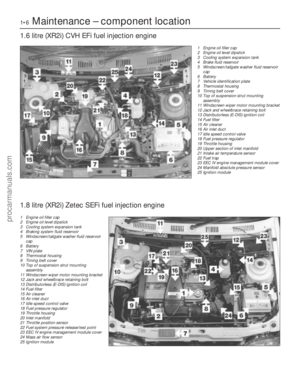 7
7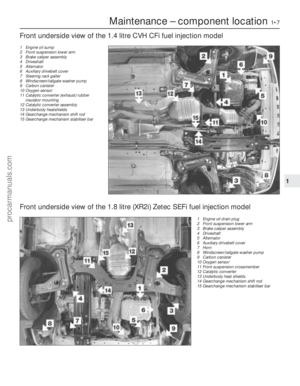 8
8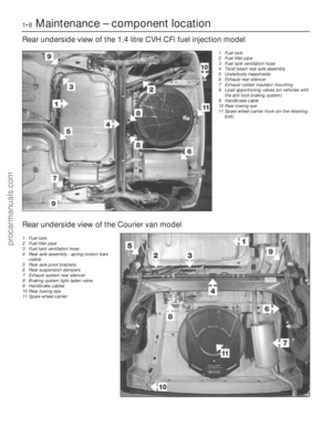 9
9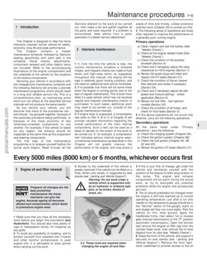 10
10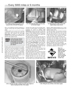 11
11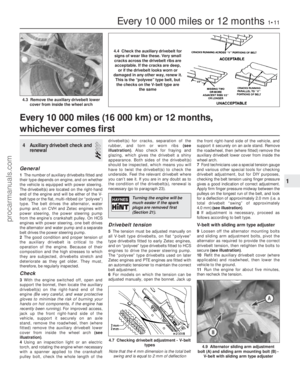 12
12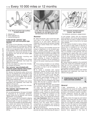 13
13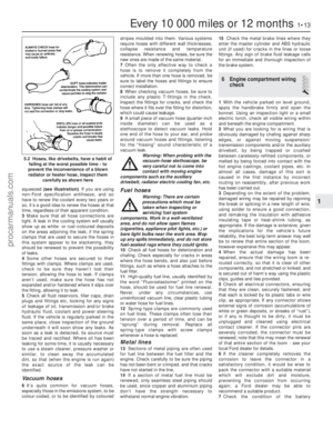 14
14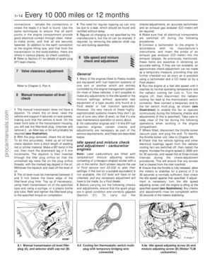 15
15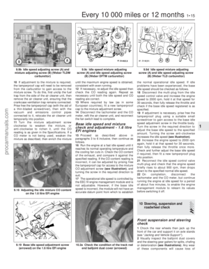 16
16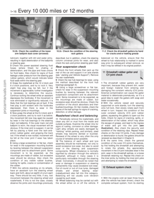 17
17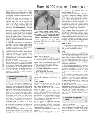 18
18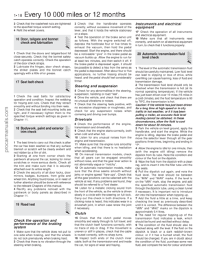 19
19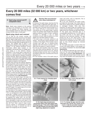 20
20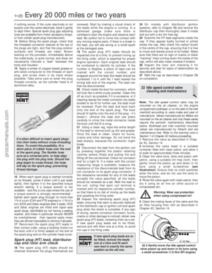 21
21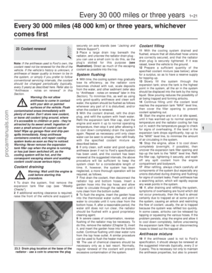 22
22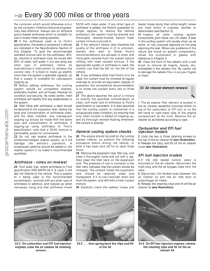 23
23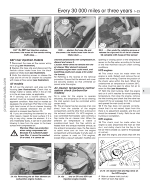 24
24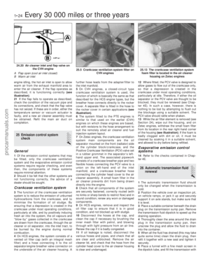 25
25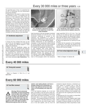 26
26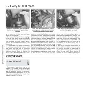 27
27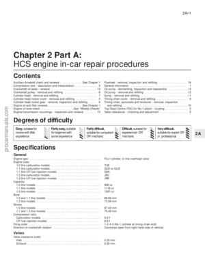 28
28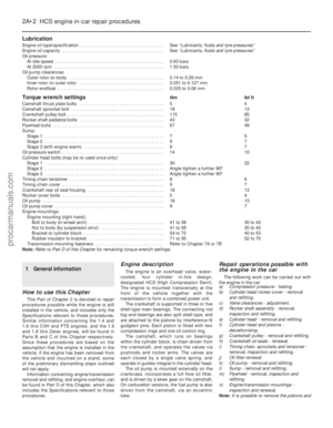 29
29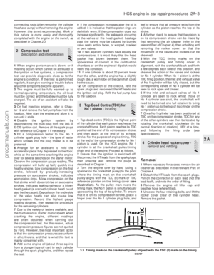 30
30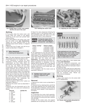 31
31 32
32 33
33 34
34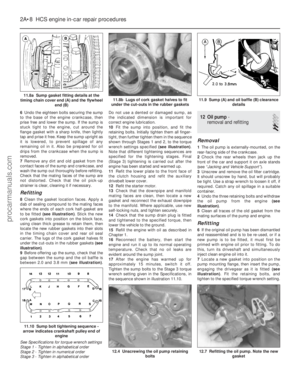 35
35 36
36 37
37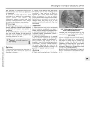 38
38 39
39 40
40 41
41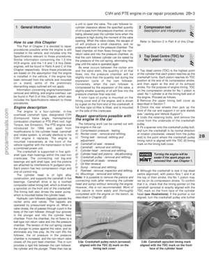 42
42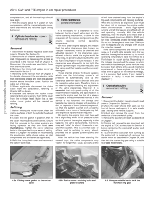 43
43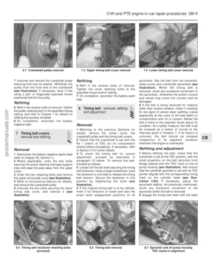 44
44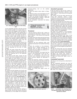 45
45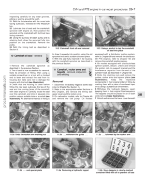 46
46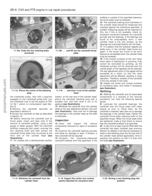 47
47 48
48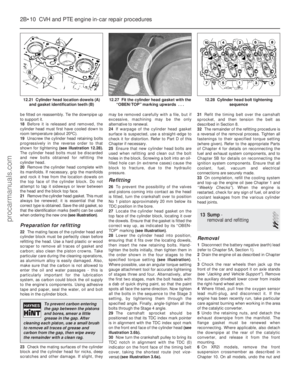 49
49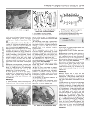 50
50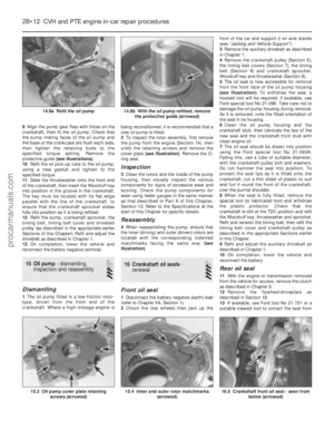 51
51 52
52 53
53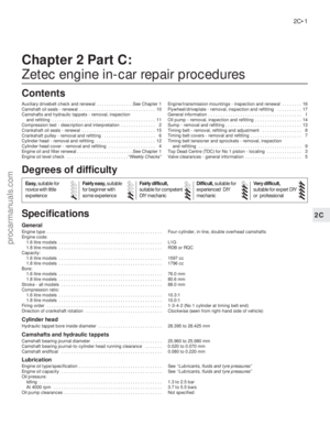 54
54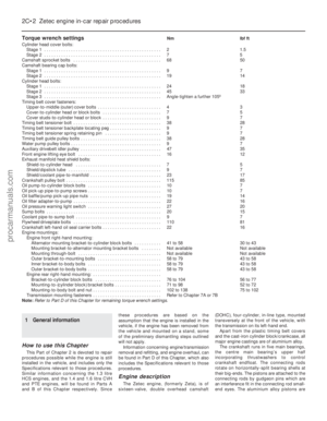 55
55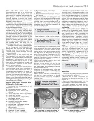 56
56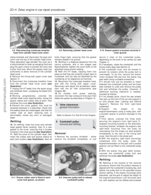 57
57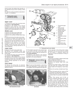 58
58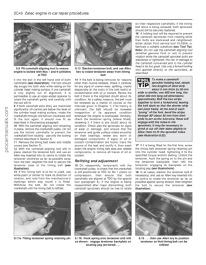 59
59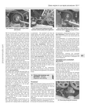 60
60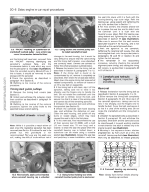 61
61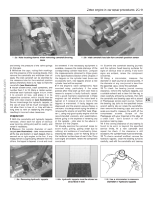 62
62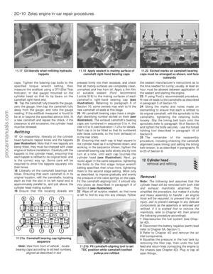 63
63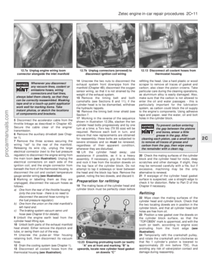 64
64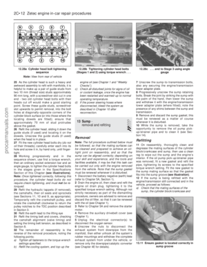 65
65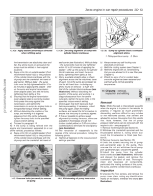 66
66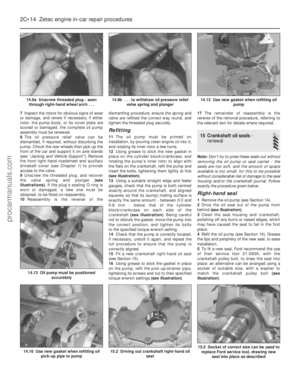 67
67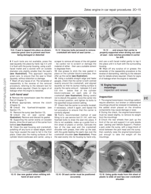 68
68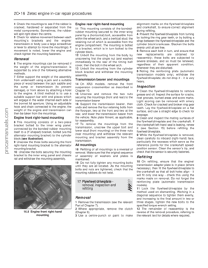 69
69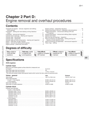 70
70 71
71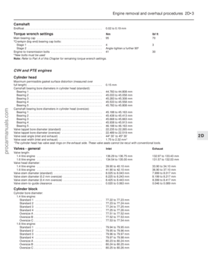 72
72 73
73 74
74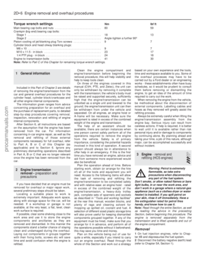 75
75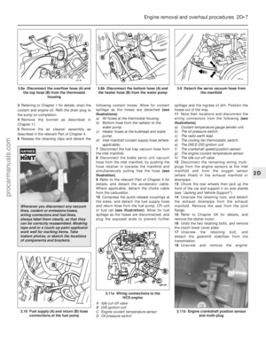 76
76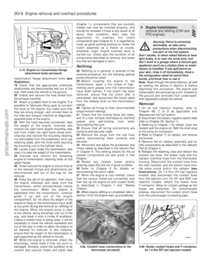 77
77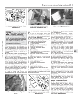 78
78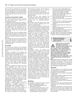 79
79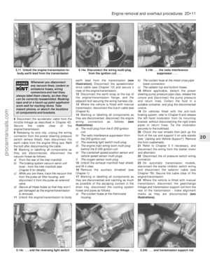 80
80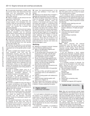 81
81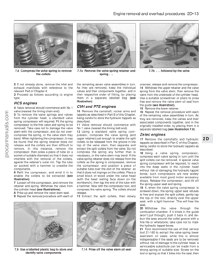 82
82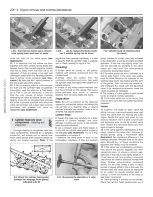 83
83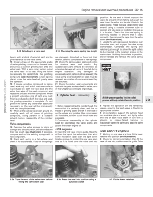 84
84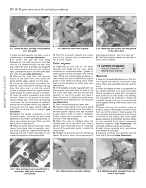 85
85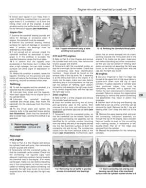 86
86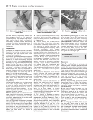 87
87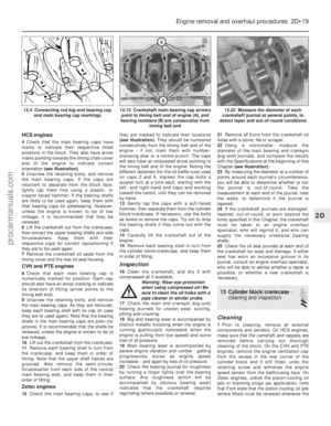 88
88 89
89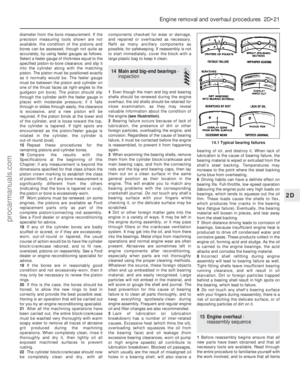 90
90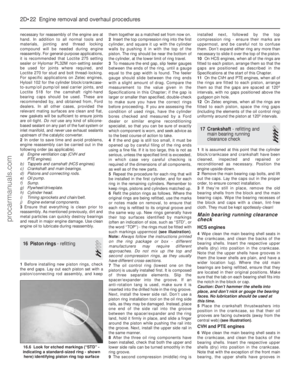 91
91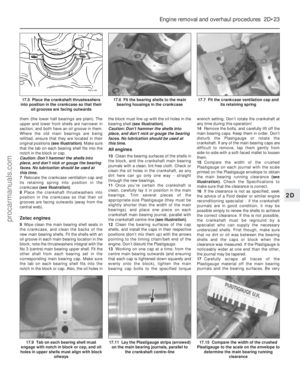 92
92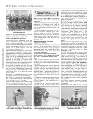 93
93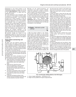 94
94 95
95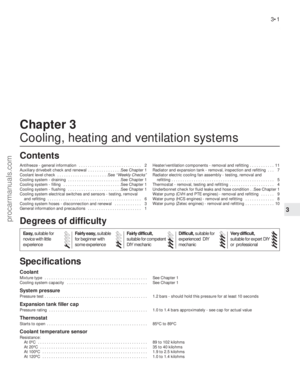 96
96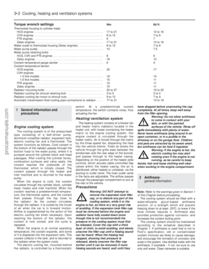 97
97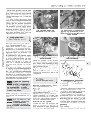 98
98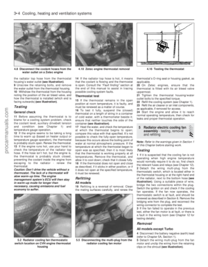 99
99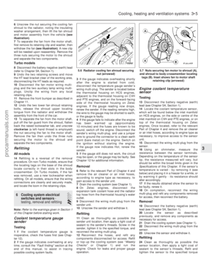 100
100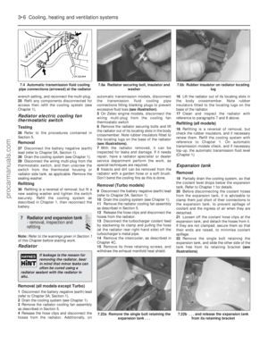 101
101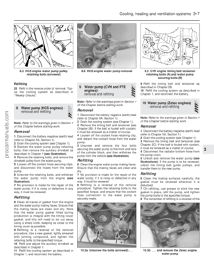 102
102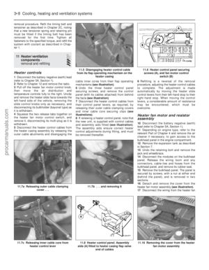 103
103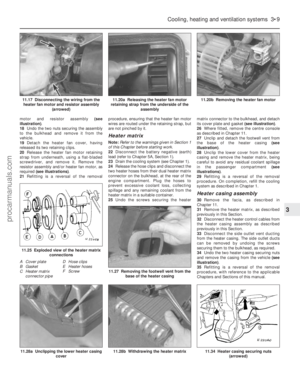 104
104 105
105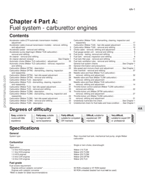 106
106 107
107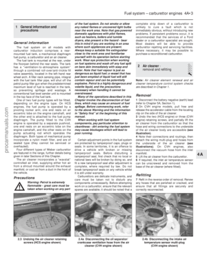 108
108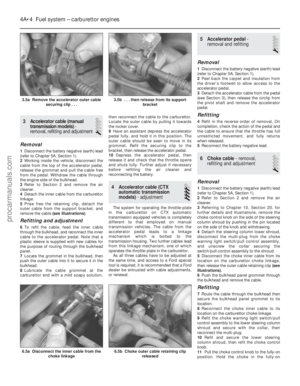 109
109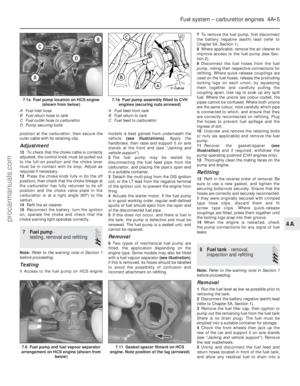 110
110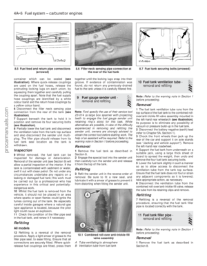 111
111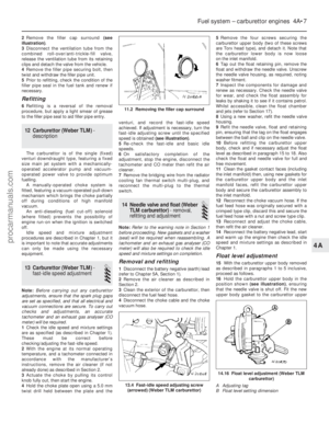 112
112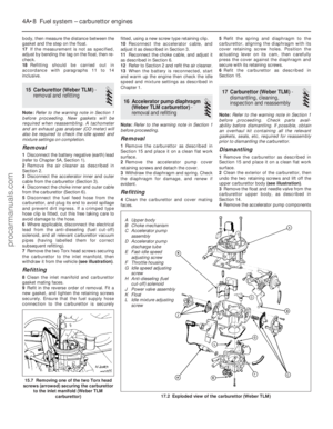 113
113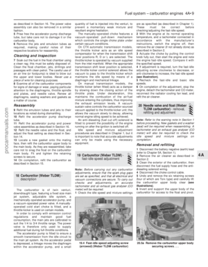 114
114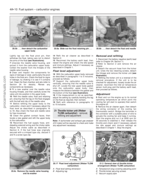 115
115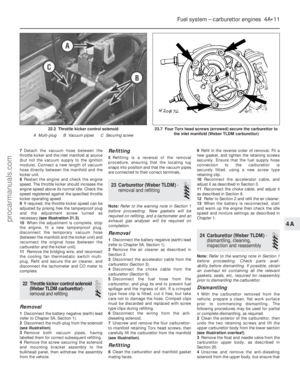 116
116 117
117 118
118 119
119 120
120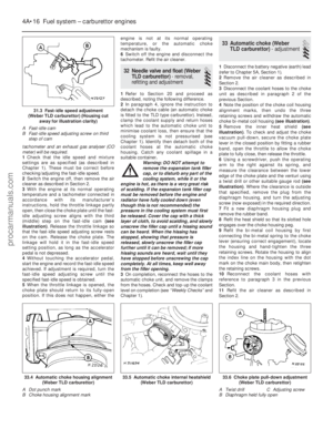 121
121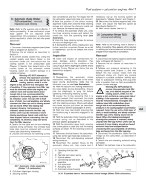 122
122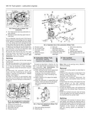 123
123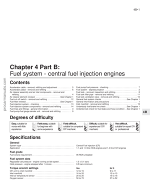 124
124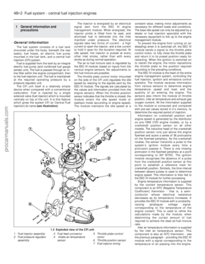 125
125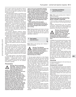 126
126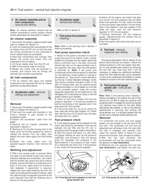 127
127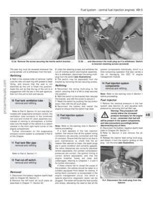 128
128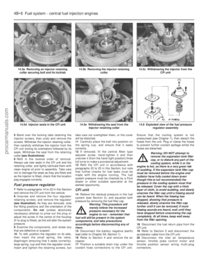 129
129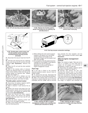 130
130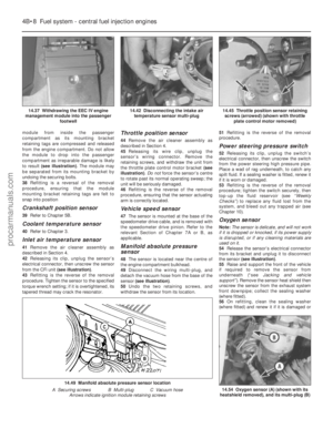 131
131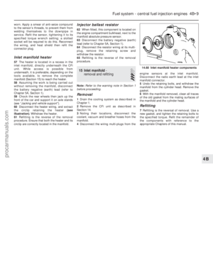 132
132 133
133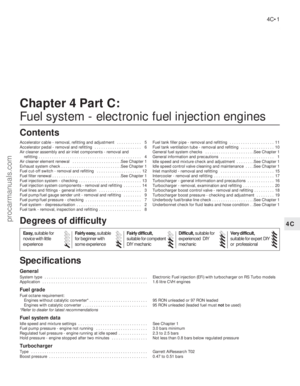 134
134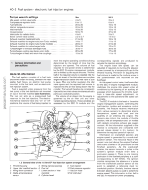 135
135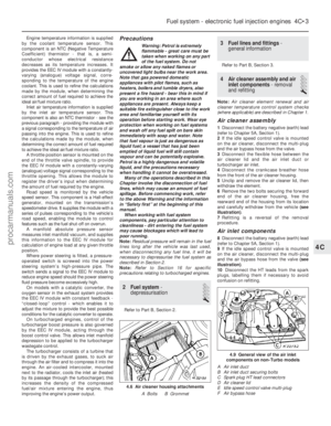 136
136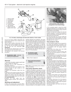 137
137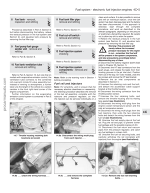 138
138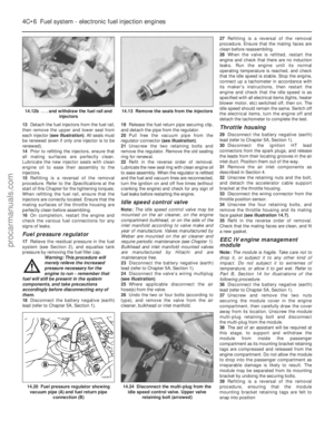 139
139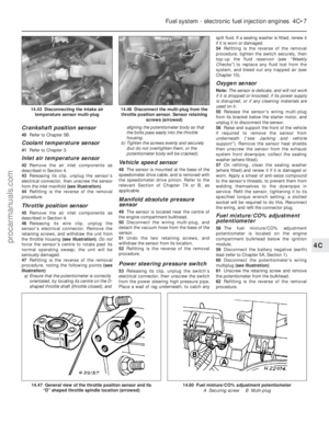 140
140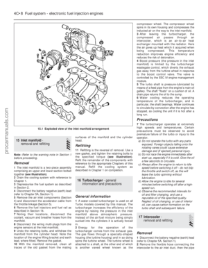 141
141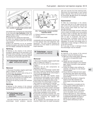 142
142 143
143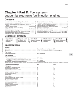 144
144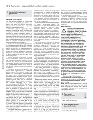 145
145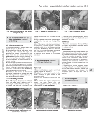 146
146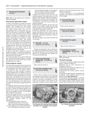 147
147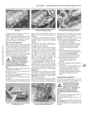 148
148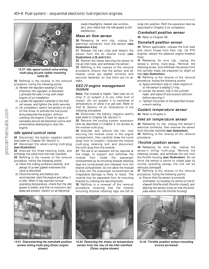 149
149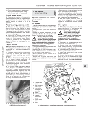 150
150 151
151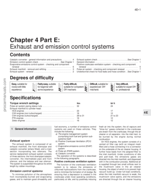 152
152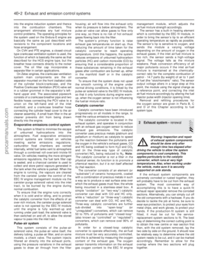 153
153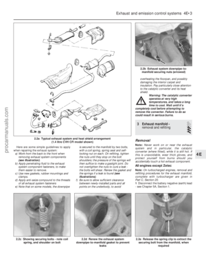 154
154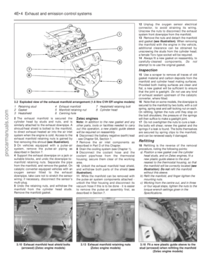 155
155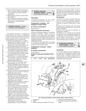 156
156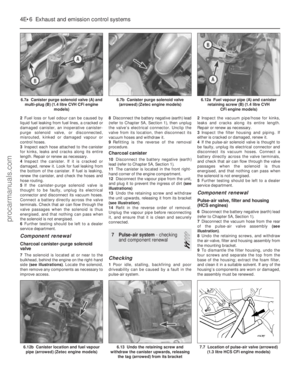 157
157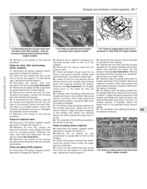 158
158 159
159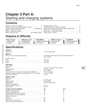 160
160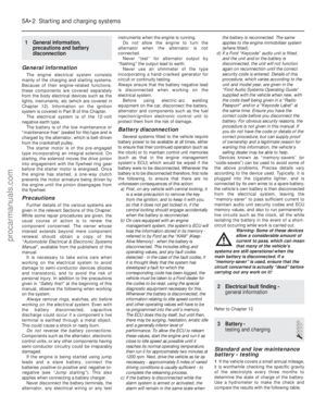 161
161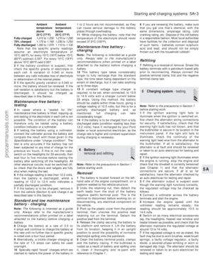 162
162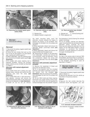 163
163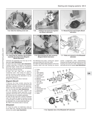 164
164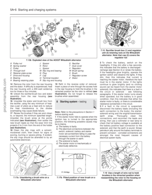 165
165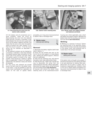 166
166 167
167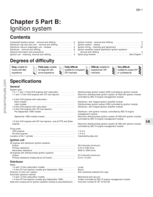 168
168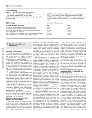 169
169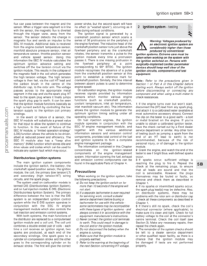 170
170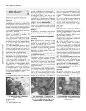 171
171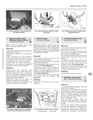 172
172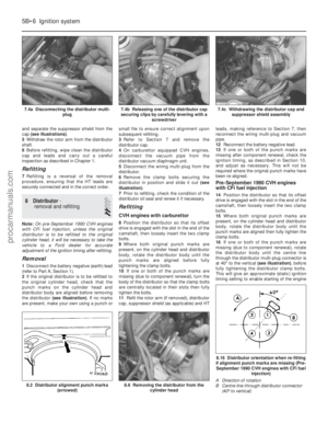 173
173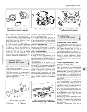 174
174 175
175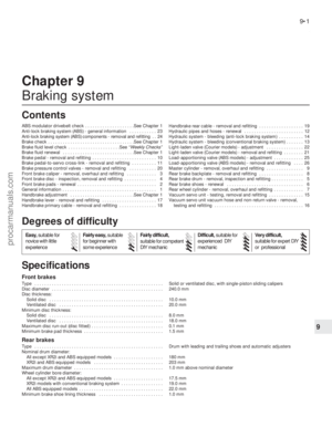 176
176 177
177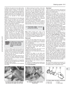 178
178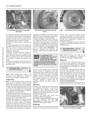 179
179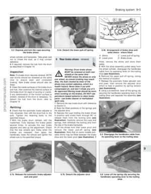 180
180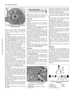 181
181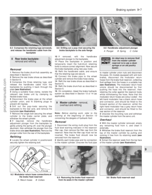 182
182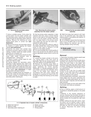 183
183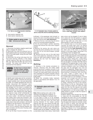 184
184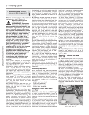 185
185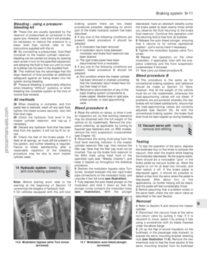 186
186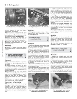 187
187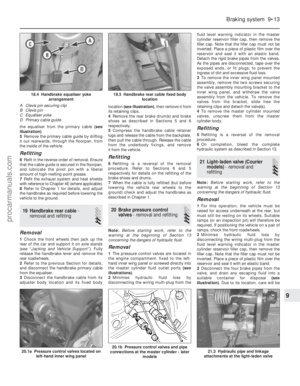 188
188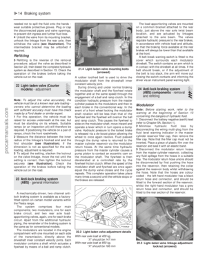 189
189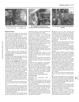 190
190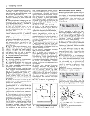 191
191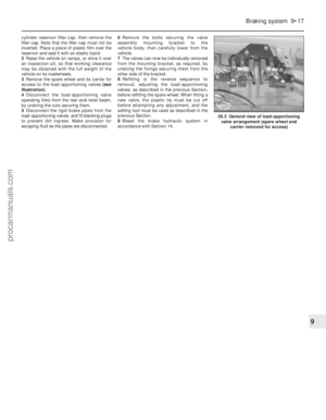 192
192 193
193 194
194 195
195 196
196 197
197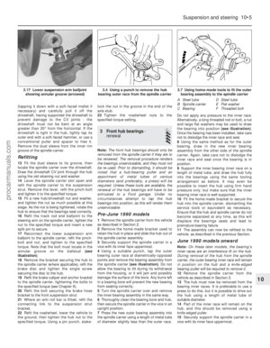 198
198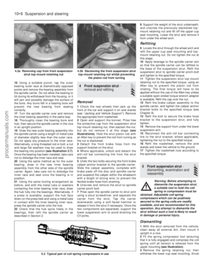 199
199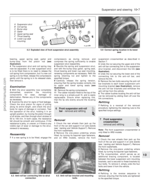 200
200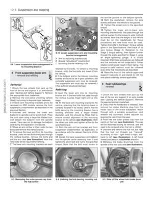 201
201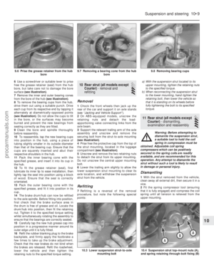 202
202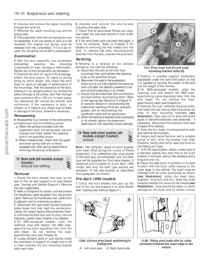 203
203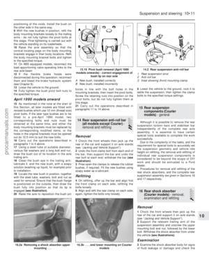 204
204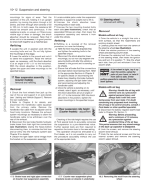 205
205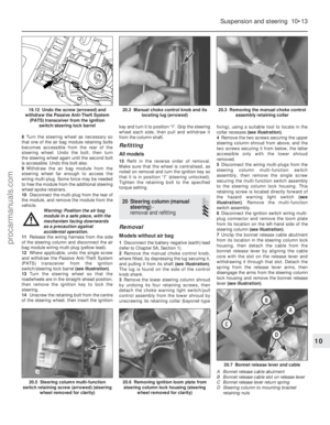 206
206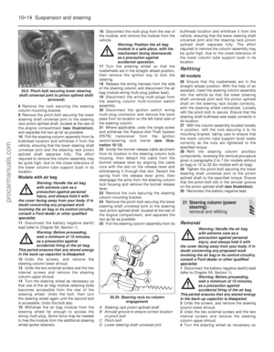 207
207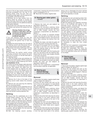 208
208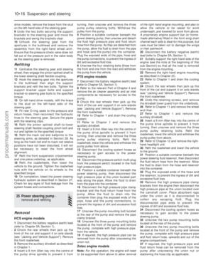 209
209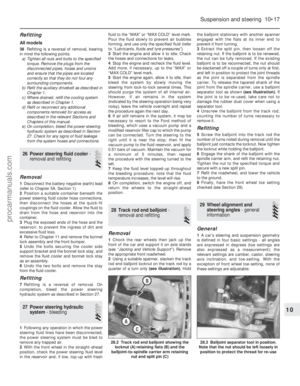 210
210 211
211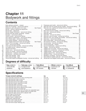 212
212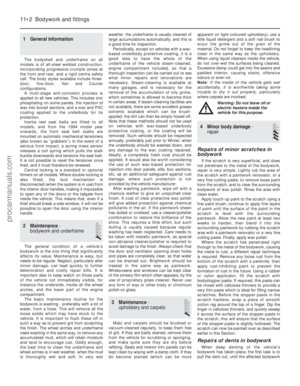 213
213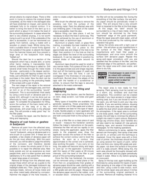 214
214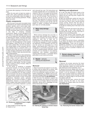 215
215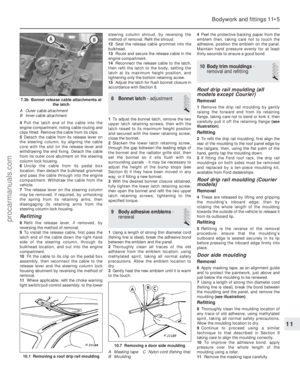 216
216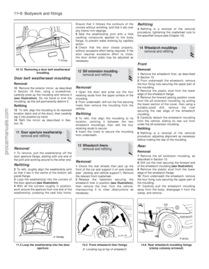 217
217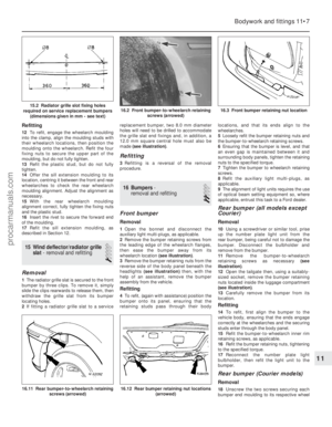 218
218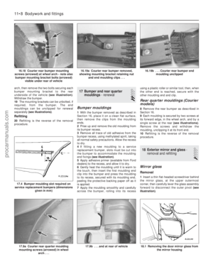 219
219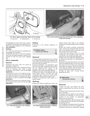 220
220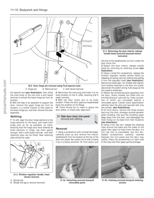 221
221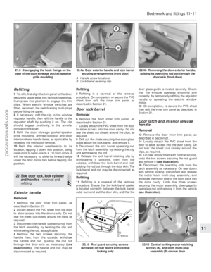 222
222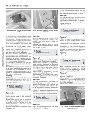 223
223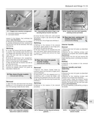 224
224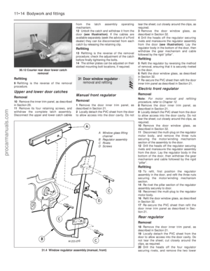 225
225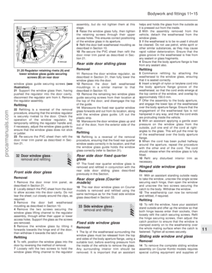 226
226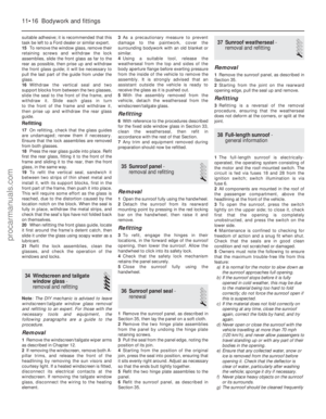 227
227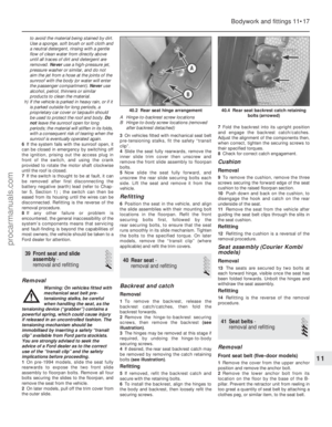 228
228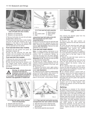 229
229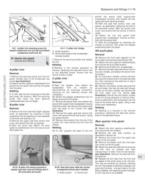 230
230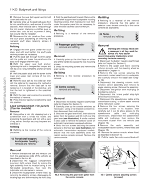 231
231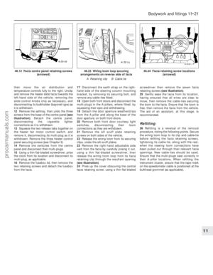 232
232 233
233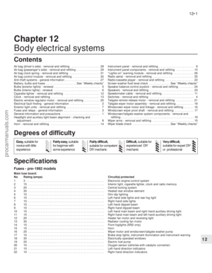 234
234 235
235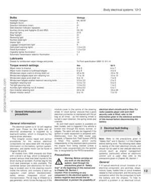 236
236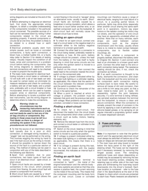 237
237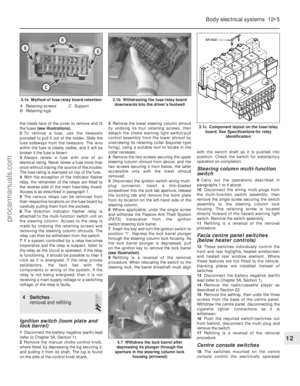 238
238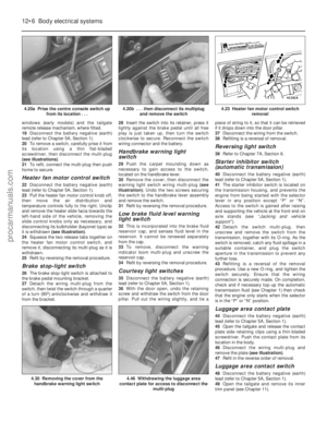 239
239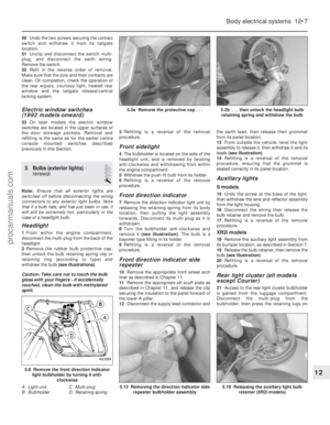 240
240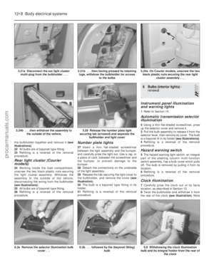 241
241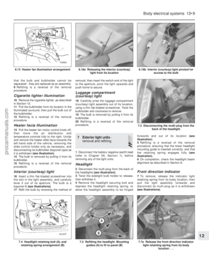 242
242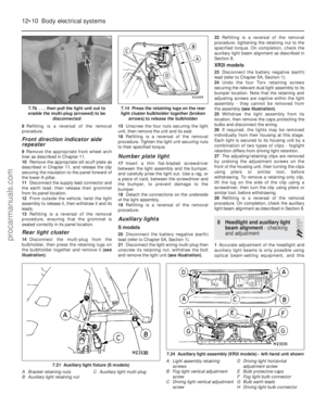 243
243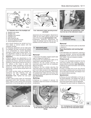 244
244 245
245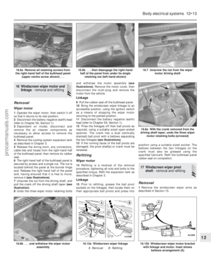 246
246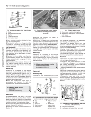 247
247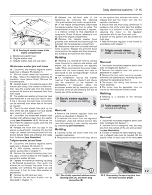 248
248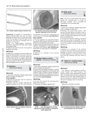 249
249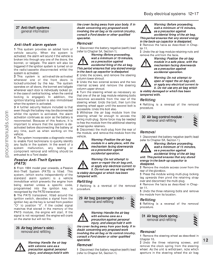 250
250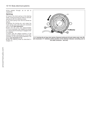 251
251 252
252 253
253 254
254 255
255 256
256 257
257 258
258 259
259 260
260 261
261 262
262 263
263 264
264 265
265 266
266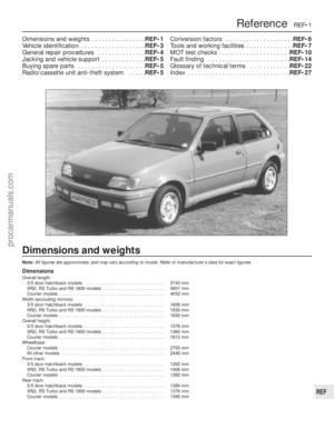 267
267 268
268 269
269 270
270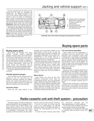 271
271 272
272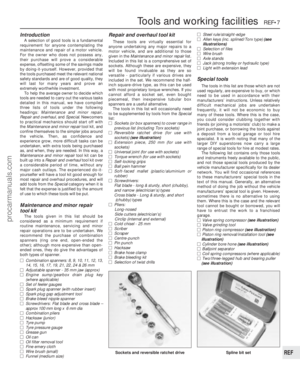 273
273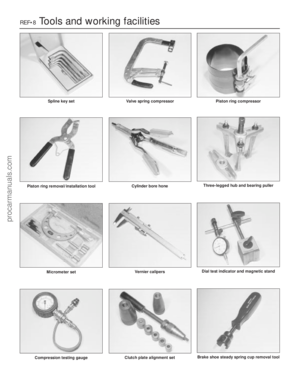 274
274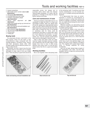 275
275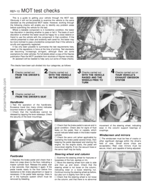 276
276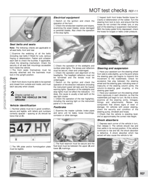 277
277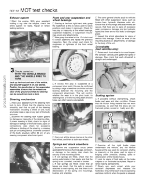 278
278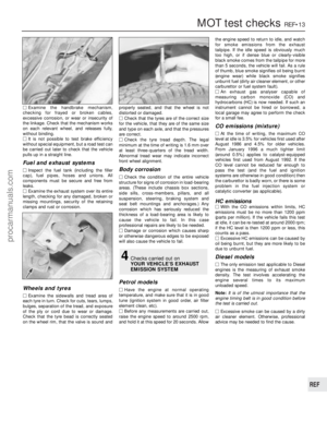 279
279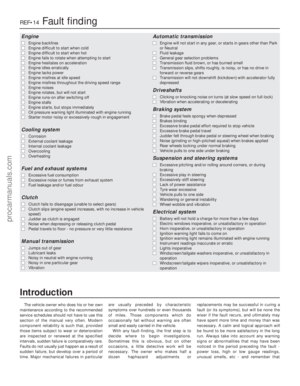 280
280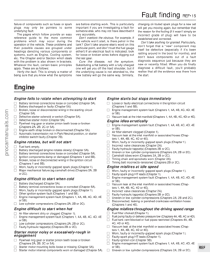 281
281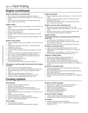 282
282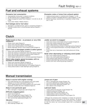 283
283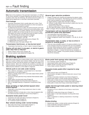 284
284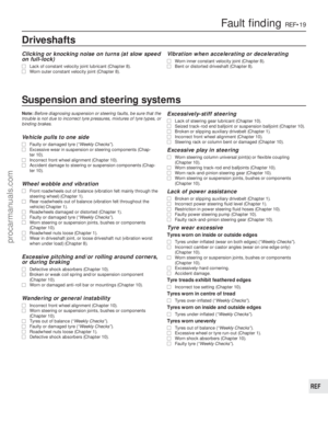 285
285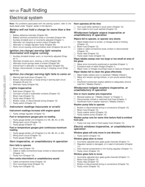 286
286 287
287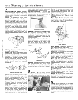 288
288 289
289 290
290 291
291 292
292 293
293 294
294 295
295